这是Teach-Repeat-Replan系统实验验证. 要在现实世界中运行此系统,请按照本页中的教程进行操作。
要在模拟中测试Teach-Repeat-Replan系统,请转到主分支。
Teach-Repeat-Replan (自主无人机竞赛)
Teach-Repeat-Replan: 复杂环境下攻击性飞行的完整而稳健的系统
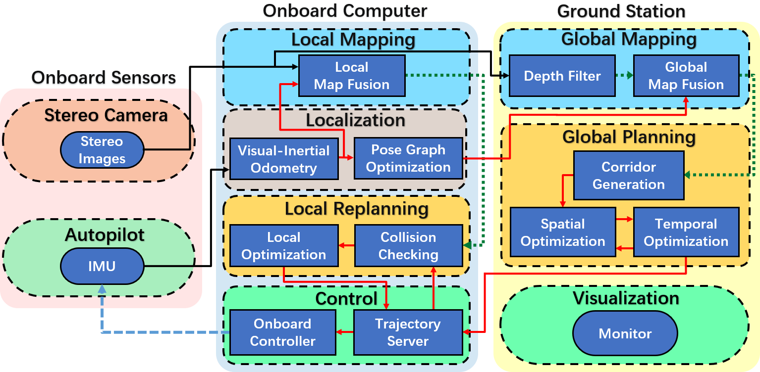
Teach-Repeat-Replan是一个能够启用自主无人机竞赛的完整而稳健的系统.它包含无人机在复杂环境中攻击性飞行的所有组件。它建立在经典的机器人教学重复框架上,该框架在基础设施检查、空中运输和搜索救援中被广泛采用。我们的系统可以捕捉用户飞行任务的意图,将任意不稳定的教学轨迹转换成保证平稳安全的重复轨迹,并生成安全的本地重新计划,以避免飞行中未映射或移动的障碍物。


架构图:
相关论文
- Teach-Repeat-Replan: A Complete and Robust System for Aggressive Flight in Complex Environments, Fei Gao, Luqi Wang, Boyu Zhou, Luxin Han, Jie Pan, shaojie Shen, IEEE Transactions on Robotics (T-RO), to appear, 2020.
- Optimal Trajectory Generation for Quadrotor Teach-and-Repeat, Fei Gao, Luqi Wang, Kaixuan Wang, William Wu, Boyu Zhou, Luxin Han, Shaojie Shen, IEEE Robotics and Automation Letters (RA-L), 2019.
如果你在你的申请或研究中使用_Teach-Repeat-Replan或其子模块,请引用我们的相关论文._ bib
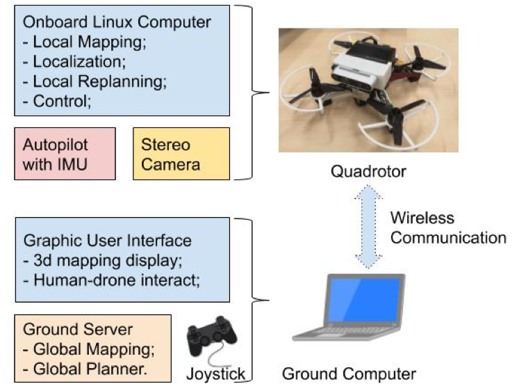
Hardware
机载计算机 (由无人机携带) 通过Wifi或以太网与地面站通信。所示下图。记得在机载计算机上启动roscore,以减少控制无人机时的数据传输延迟。
教程
1.经过测试的硬件/软件
通过以下测试的硬件/软件组合是 dji N3 飞行控制器, dji Manifold 2-C 机载计算机, dji Lightbridge2 遥控器, intel realsense D435i camera and Ubuntu 16.04.
2. 安装驱动程序和依赖项
- Run
./install_tools.shscript in the src folder to install necessary dependencies. 如果出现任何问题,请打开此脚本并手动逐个安装它们。 - Follow the instruction1 to install the drivers for N3 flight controller on onboard computer. version 3.7 of Onboard-SDK is recomended.
- Follow the instruction2 to install the drivers for intel realsense on onboard computer.
- Install necessary solvers Mosek, OOQP, Ceres and NLopt. You can refer to simulation for more details.
3. 在板载计算机上编译代码
在此目录中的板载计算机和src文件夹上创建ros工作区, 将onboardcomputer中的所有文件移动到新创建的src文件夹, and compile the project in the workspace with catkin_make command. 如果提示您缺少库,请在Google上搜索并安装missings. Finally, add the script source <your_catkin_ws>/devel/setup.bash to ~/.bashrc_.
4. 配置和运行VIO模块-vins-fusion
- Run djiros to get IMU data from N3
Use the USB cable to connect the N3 flight controller to DJI Assistant2 software, check the Enable API box and select baud rate to 921600, 然后拔掉电源线并插上电源,重新启动飞行控制器。
Use CP2102 module to connect Manifold-2C to N3 flight controller. Fill out the APP ID and APP KEY parameter to
Run roslaunch djiros djiros.launch, and then run rostopic hz /djiros/imu. It can be seen that the frequency of data output of imu is 400HZ, which means success.
- 运行realsense以获取深度和灰度图像
Just run roslaunch realsense2_camera rs_camera.launch. 如果报告了错误,请尝试重新插入USB接口t. After that, run rqt_image_viewer and select /camera/depth/image_rect_raw or /camera/infra1/image_rect_raw to check if the display is correct.
- 配置摄像机参数
Enter
然后在同一个目录中, open left.yaml, 这是左摄像机的参数配置文件. Configure camera resolution, distortion factor, intrinsic parameters, etc. 同样,打开右侧的.yaml文件并填写右侧摄像机的参数。
- Run VINS-Fusion
Now it is time to run the whole VIO system. Enter
Make sure that all the ros nodes are killed and run ./sensing_estimation.sh in
5. 地面计算机和机载计算机之间的通信
- 将地面计算机和板载计算机连接到同一LAN网络,以便它们可以相互ping通. Enter the
ifconfigcommand to get the IP addresses at both computers. If the IP of the onboard computer is 192.168.1.100 and the IP of the ground computer is 192.168.1.101, than at the end of the ~/.bashrc on onboard computer, add the code below:
export ROS_HOSTNAME = 192.168.1.100export ROS_MASTER_URI = http://192.168.1.100:11311
在地面计算机上,在同一文件中添加以下代码:
export ROS_HOSTNAME = 192.168.1.101export ROS_MASTER_URI = http://192.168.1.100:11311
Then `source ~/.bashrc` on both computers.
- Communication Test: Running any node on the onboard computer and then entering
rostopic liston the ground computer, topics should show up on the ground side, which means communication success.
6. Mapping
- Compile the code in ground_station folder in ROS workspace on the ground computer.
- Create a new folder ~/output/pose_graph/ on the onboard computer to store the pose graph generated during mapping. Run
./sensing_estimation.sh. (It is highly recommended that the rviz statement be manually commented out to save computing resources.) - Open
/src/global_mapping/surfel_fusion/launch/global_map_fusion.launch on the ground computer and correctly modify the intrinsics and extrinsics of the camera. Modify the path of the .rviz file in mapping.sh, and then run
./mapping.sh. Move the quadrotor around and you will see Fig.2 below if everything goes well.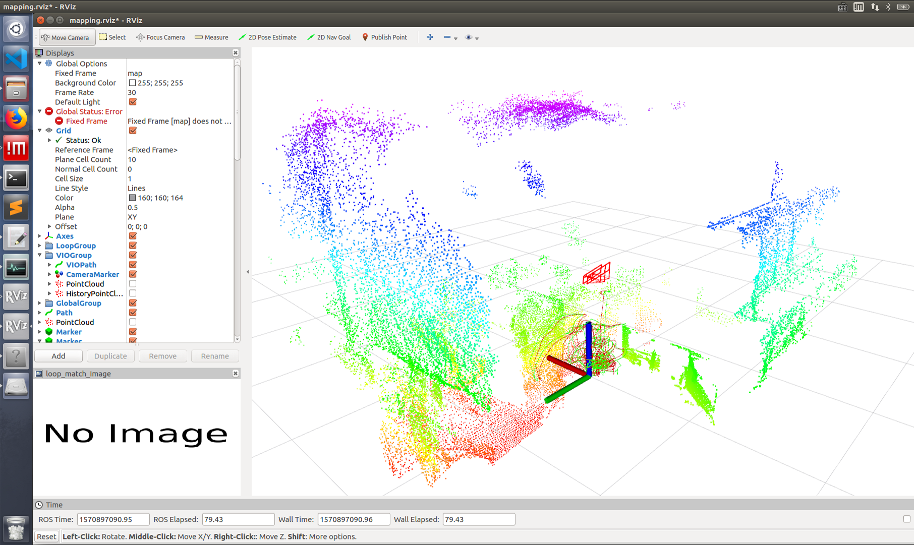
After the mapping phase is finished, the ground computer can be closed by Ctrl+C. The program will save the point cloud data automatically before exiting and the file name is model.pcd. The onboard computer can not use Ctrl+C to shut down directly after mapping phase for that it needs to save the pose graph got during mapping and this process must be operated by inputing “s“ and press “Enter” manually. Then the onboard computer will save the recorded pose graph to the ~/output/pose_graph folder.
P.S.
- 确保板载计算机和地面计算机之间的网络速度至少可以达到 20 mb/s。可以在系统监控软件中查看通信速度。如果无线网络速度不够,建议在建图时使用有线连接。
- If you want to rebuild the map, you need to delete all the existed files
in the ~/output/pose_graph/ folder.
7. 测试四旋翼是否正常运行
- Modify the path of the realsense_stereo_imu_config.yaml file related to VINS in the script file ctrl_estimation_replanning.sh, and then run the
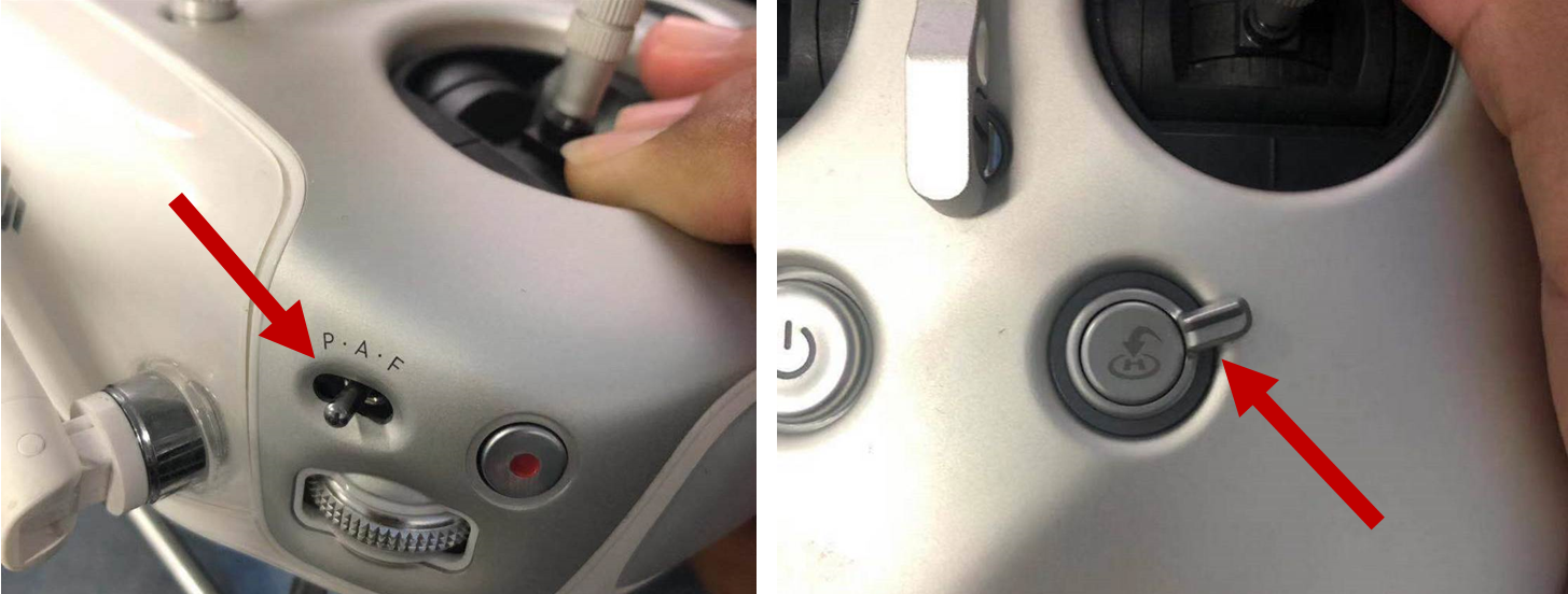
./ctrl_estimation_replanning.shscript on the onboard computer. Try to fly. Firstly, put the small switch(see the left picture of Fig.3) lies in the left upper side of the remote controller to stay at position “A”, and move the “H” switch(see the right picture of Fig.3) that in right bottom side of the remote controller to hit up. Then take the quadrotor off, in the air, move the left upper switch from A to P and the aircraft should perform fixed-point immediately that stablely hovering in the air, that means the controller operates correctly.
8. 执行 Teach-Repeat-Replan
Modify the camera parameters in
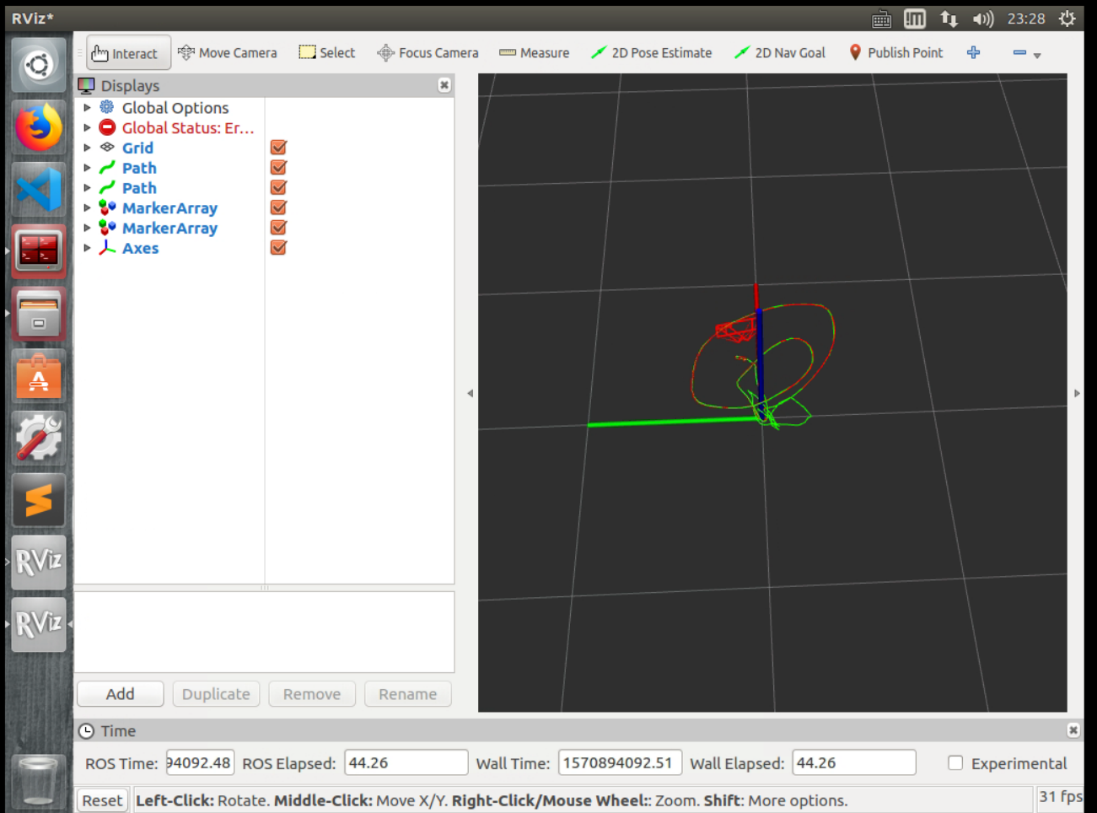
/src/local_replanner/local_replanner/launch/local_replanner.launch , and then runctrl_estimation_replanning.shon the onboard computer, waiting for pose graph to be added (possibly more than 1 minute), which will be prompted in terminal after loading.Modify the name of point cloud file during mapping in the teaching_planning.sh script file, and then run the
./teaching_planning.sh. The rviz will be like Fig.4.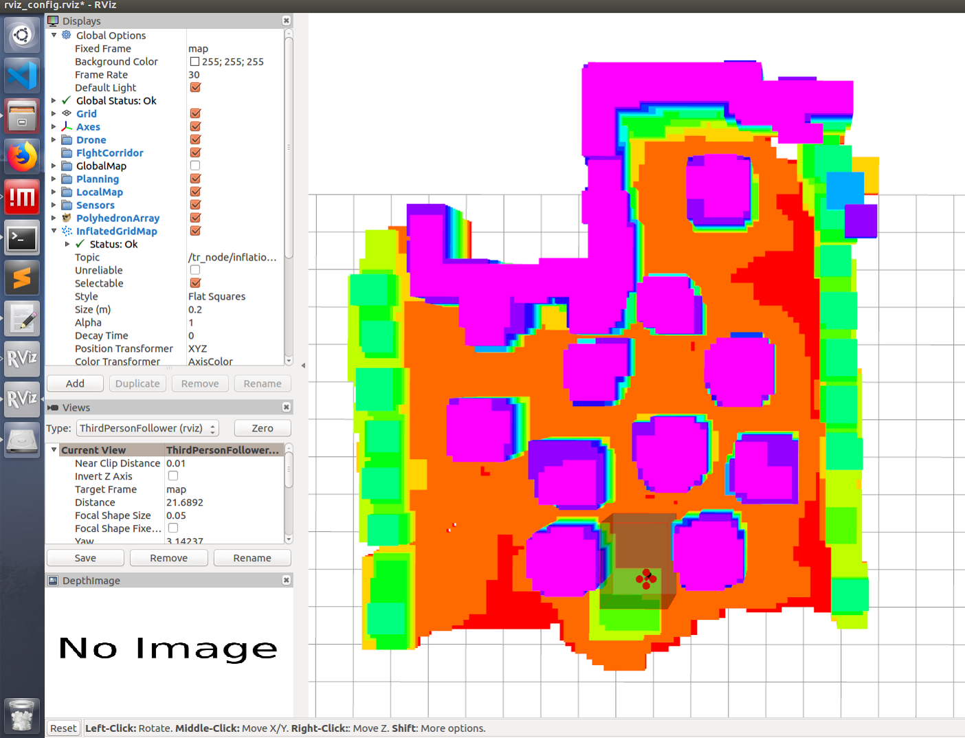
Then use the Xbox joystick or keyboard to draw a trajectory in rviz(teach phrase).
- Start the quadrotor with a remote control while keeping the upper left switch be selected in A and the lower right “H” switch in the position up. At an altitude of about one meter, move the upper left switch from A to P, the quadrotor will enter a stable hovering state, and then move the lower right “H” switch down. If nothing goes wrong, the quadrotor will automatically start to execute the desired trajectory.
到目前为止,整个系统已经成功运行。
9. 故障排除
如果出现无法解释的错误,您可以尝试重新启动板载计算机和地面计算机。
尽量不要在板载计算机上运行rviz,这会占用太多资源并对性能产生负面影响。- If the quadrotor can not be armed, then we need to unplug the USB/serial module and restart the flight controller, finally plug the USB/serial module. Make sure the USB/serial module is disconnected when the flight controller is powering on.
如果realsense无法启动,则可以通过再次拔出/插入电源来解决。
始终注意通信质量、高延迟和低网络速度,这将导致意想不到的问题。
如果在教学和重复阶段无法生成轨迹,建议缓慢教学并确保rviz中生成的所有多面体不间断。
由于本地replaner在realworld中不稳定,因此已在代码中临时阻止它。请等待更新。缺乏局部重刨机不会影响全球轨迹的产生和飞行,但无法避免飞行过程中出现的意外障碍。10.硬件列表
无人机架: Q250;
电机和电子稳定控制系统: DJI snail;
螺旋桨: DJI 5048s;
电池: tattu4s2300mah;
遥控器: DJI lightbridge2;
自动驾驶仪: DJI N3;
机载计算机: DJI manifold2

若有收获,就点个赞吧
0 人点赞
