JTAG详解
参考资料
JTAG硬件说明
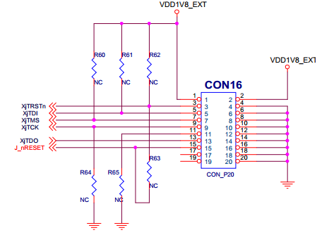
- JTAG引脚定义: JTAG有10pin的、14pin的和20pin-标准
JTAG(Joint Test Action Group,联合测试行动组)调试接口目前主要有10针,14针和20针。
必须有的信号-5个:
- TMS:测试模式选择,TMS用来设置JTAG接口处于某种特定的测试模式,必须在目标板上将此引脚上拉;
- TCK:测试时钟输入,建议在目标板上将此引脚上拉;
- TDI:测试数据输入,仿真器连接至目标CPU的数据输入信号,建议在目标板上上拉到VDD;
- TDO:测试数据输出,目标板返回给仿真器的数据信号;
- VREF:目标表参考电压信号,用于检测目标板是否供电,直接与目标板VDD相连,并不向外提供输出电压;
可选信号:
- RTCK:目标板提供仿真器的时钟信号,有些项目中是要求JTAG的输入与其内部时钟信号同步,仿真器利用此引脚的输入可动态的控制自己的TCK速率;
- TRST:JTAG复位,连接到目标板CPU的nTRST引脚,用于复位CPU调试接口的TAP控制器;目标板上应该将此脚上拉到高电位,避免意外复位,可选引脚—复位JTAG;
- RESET:仿真器输出至目标CPU的系统复位信号,可选信号-复位CPU;
- USER IN / USER OUT :用户自定义输入输出
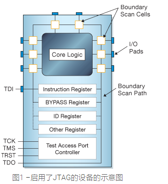
JTAG原理
硬件接口
边界扫描
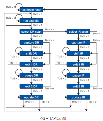
TAP状态机
使用JLINK调试ARM
参考资料:
J-Link是德国SEGGER公司推出基于JTAG的仿真器。简单地说,是给一个JTAG协议转换盒,即一个小型USB到JTAG的转换盒,其连接到计算机用的是USB接口,而到目标板内部用的还是jtag协议。它完成了一个从软件到硬件转换的工作。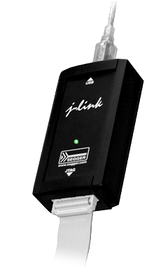
JTAG Probe
JLINK硬件说明
淘宝链接: JLINK硬件支持SWD和JTAG两种模式,可选使用。转接板信息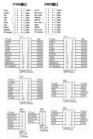
JLINK工具
wiki系列
快速命令:rt # trestdevice cortex-a7si jtagspeed 100connecti # read idJ-Link>?Available commands are:----------------------f Firmware infoh haltIsHalted Returns the current CPU state (halted / running)WaitHalt Waits until the CPU is halted or the given timeout is exceeded.Syntax: WaitHalt <TimeoutMs> Default timeout is 1000 msg goSleep Waits the given time (in milliseconds). Syntax: Sleep <delay>s Single step the target chipSyntax: s [<NumSteps (dec)>]st Show hardware statushwinfo Show hardware infomem Read memory. Syntax: mem [<Zone>:]<Addr>, <NumBytes> (hex)mem8 Read 8-bit items. Syntax: mem8 [<Zone>:]<Addr>, <NumBytes> (hex)mem16 Read 16-bit items. Syntax: mem16 [<Zone>:]<Addr>, <NumItems> (hex)mem32 Read 32-bit items. Syntax: mem32 [<Zone>:]<Addr>, <NumItems> (hex)w1 Write 8-bit items. Syntax: w1 [<Zone>:]<Addr>, <Data> (hex)w2 Write 16-bit items. Syntax: w2 [<Zone>:]<Addr>, <Data> (hex)w4 Write 32-bit items. Syntax: w4 [<Zone>:]<Addr>, <Data> (hex)erase Erase internal flash of selected device. Syntax: Erasewm Write test words. Syntax: wm <NumWords>is Identify length of scan chain select registerms Measure length of scan chain. Syntax: ms <Scan chain>mr Measure RTCK react time. Syntax: mrq Quitqc Close JLink connection and quiteoe Exit on errorSyntax: eoe <1/0>r Reset target (RESET)rx Reset target (RESET). Syntax: rx <DelayAfterReset>RSetType Set the current reset type. Syntax: RSetType <type>Regs Display contents of registerswreg Write register. Syntax: wreg <RegName>, <Value>moe Shows mode-of-entry, meaning: Reason why CPU is haltedSetBP Set breakpoint. Syntax: SetBP <addr> [A/T] [S/H]SetWP Set Watchpoint. Syntax: <Addr> [R/W] [<Data> [<D-Mask>] [A-Mask]]ClrBP Clear breakpoint. Syntax: ClrBP <BP_Handle>ClrWP Clear watchpoint. Syntax: ClrWP <WP_Handle>VCatch Write vector catch. Syntax: VCatch <Value>loadfile Load data file into target memory.Syntax: loadfile <filename>, [<addr>]Supported extensions: *.bin, *.mot, *.hex, *.srec<addr> is needed for bin files only.loadbin Load *.bin file into target memory.Syntax: loadbin <filename>, <addr>savebin Saves target memory into binary file.Syntax: savebin <filename>, <addr>, <NumBytes>verifybin Verfies if the specified binary is already in the target memory at the specified address.Syntax: verifybin <filename>, <addr>SetPC Set the PC to specified value. Syntax: SetPC <Addr>le Change to little endian modebe Change to big endian modelog Enables log to file. Syntax: log <filename>unlock Unlocks a device. Syntax: unlock <DeviceName>Type unlock without <DeviceName> to get a listof supported device names.nRESET has to be connectedterm Test command to visualize printf output from the target device,using DCC (SEGGER DCC handler running on target)ReadAP Reads a CoreSight AP register.Note: First read returns the data of the previous read.An additional read of DP reg 3 is necessary to get the data.ReadDP Reads a CoreSight DP register.Note: For SWD data is returned immediately.For JTAG the data of the previous read is returned.An additional read of DP reg 3 is necessary to get the data.WriteAP Writes a CoreSight AP register.WriteDP Writes a CoreSight DP register.SWDSelect Selects SWD as interface and outputsthe JTAG -> SWD switching sequence.SWDReadAP Reads a CoreSight AP register via SWD.Note: First read returns the data of the previous read.An additional read of DP reg 3 is necessary to get the data.SWDReadDP Reads a CoreSight DP register via SWD.Note: Correct data is returned immediately.SWDWriteAP Writes a CoreSight AP register via SWD.SWDWriteDP Writes a CoreSight DP register via SWD.Device Selects a specific device J-Link shall connect toand performs a reconnect.In most cases explicit selection of the device is not necessary.Selecting a device enables the user to make use of the J-Linkflash programming functionality as well as using unlimitedbreakpoints in flash memory.For some devices explicit device selection is mandatory in orderto allow the DLL to perform special handling needed by the device.ExpDevList Exports the device names from the DLL internaldevice list to a text fileSyntax: ExpDevList <Filename>ExpDevListXML Exports the device names from the DLL internaldevice list to a text file in XML formatSyntax: ExpDevListXML <Filename>PowerTrace Perform power trace (not supported by all models)Syntax: PowerTrace <LogFile> [<ChannelMask> <RefCountSel>]<LogFile>: File to store power trace data to<ChannelMask>: 32-bit mask to specify what channels shall be enabled<SampleFreq>: Sampling frequency in Hz (0 == max)<RefCountSel>: 0: No reference count1: Number of bytes transmitted on SWO---- CP15 ------------rce Read CP15. Syntax: rce <Op1>, <CRn>, <CRm>, <Op2>wce Write CP15. Syntax: wce <Op1>, <CRn>, <CRm>, <Op2>, <Data>---- ICE -------------Ice Show state of the embedded ice macrocell (ICE breaker)ri Read Ice reg. Syntax: ri <RegIndex>(hex)wi Write Ice reg. Syntax: wi <RegIndex>, <Data>(hex)---- TRACE -----------TClear TRACE - Clear bufferTSetSize TRACE - Set Size of trace bufferTSetFormat TRACE - SetFormatTSR TRACE - Show Regions (and analyze trace buffer)TStart TRACE - StartTStop TRACE - Stop---- SWO -------------SWOSpeed SWO - Show supported speedsSWOStart SWO - StartSWOStop SWO - StopSWOStat SWO - Display SWO statusSWORead SWO - Read and display SWO dataSWOShow SWO - Read and analyze SWO dataSWOFlush SWO - Flush dataSWOView SWO - View terminal data---- PERIODIC --------PERConf PERIODIC - ConfigurePERStart PERIODIC - StartPERStop PERIODIC - StopPERStat PERIODIC - Display statusPERRead PERIODIC - Read and display dataPERShow PERIODIC - Read and analyze data---- File I/O --------fwrite Write file to emulatorfread Read file from emulatorfshow Read and display file from emulatorfdelete Delete file on emulatorfsize Display size of file on emulatorflist List directory on emulatorSecureArea Creates/Removes secure area on probe---- Test ------------TestHaltGo Run go/halt 1000 timesTestStep Run step 1000 timesTestCSpeed Measure CPU speed.Parameters: [<RAMAddr>]TestWSpeed Measure download speed into target memory.Parameters: [<Addr> [<Size>]]TestRSpeed Measure upload speed from target memory.Parameters: [<Addr> [<Size>] [<NumBlocks>]]TestNWSpeed Measure network download speed.Parameters: [<NumBytes> [<NumReps>]]TestNRSpeed Measure network upload speed.Parameters: [<NumBytes> [<NumReps>]]---- JTAG ------------JTAGConf Set number of IR/DR bits before ARM device.Syntax: Config <IRpre>, <DRpre>speed Set target interface speed. Syntax: speed <freq>|auto|adaptive, e.g. speed 2000, speed ai Read JTAG Id (Host CPU)wjc Write JTAG command (IR). Syntax: wjc <Data>(hex)wjd Write JTAG data (DR). Syntax: wjd <Data64>(hex), <NumBits>(dec)RTAP Reset TAP Controller using state machine (111110)wjraw Write Raw JTAG data. Syntax: wjraw <NumBits(dec)>, <tms>, <tdi>rt Reset TAP Controller (nTRST)---- JTAG-Hardware ---c00 Create clock with TDI = TMS = 0c Clocktck0 Clear TCKtck1 Set TCK0 Clear TDI1 Set TDIt0 Clear TMSt1 Set TMStrst0 Clear TRSTtrst1 Set TRSTr0 Clear RESETr1 Set RESET---- Connection ------usb Connect to J-Link via USB. Syntax: usb <port>, where port is 0..3ip Connect to J-Link ARM Pro or J-Link TCP/IP Server via TCP/IP.Syntax: ip <ip_addr>---- Configuration ---si Select target interface. Syntax: si <Interface>,where <Interface> can be any supported target interface (e.g SWD, JTAG, ICSP, FINE, ...power Switch power supply for target. Syntax: power <State> [perm],where State is either On or Off. Example: power on permwconf Write configuration byte. Syntax: wconf <offset>, <data>rconf Read configuration bytes. Syntax: rconflicense Shows a list of all available license commandsipaddr Show/Assign IP address and subnetmask of/to the connected J-Link.gwaddr Show/Assign network gateway address of/to the connected J-Link.dnsaddr Show/Assign network DNS server address of/to the connected J-Link.conf Show configuration of the connected J-Link.calibrate Calibrate the target current measurement.selemu Select a emulator to communicate with,from a list of all emulators which are connected to the hostThe interfaces to search on, can be specifiedSyntax: selemu [<Interface0> <Interface1> ...]ShowEmuList Shows a list of all emulators which are connected to the host.The interfaces to search on, can be specified.Syntax: ShowEmuList [<Interface0> <Interface1> ...]VCOM enable/disable VCOM. Takes effect after power cycle of the J-LinkSyntax: VCOM <enable|disable>VTREF Sets a fixed value for VTref on J-Link.Syntax: VTREF <ValuemV>----------------------
J-Flash有Linux和Windows版本,支持以下Flash烧写:
- Supports most Cortex A-R-M, RX and Power PC devices/cores
- Supports the following internal and external flash devices:
- Internal flash of most popular microcontrollers
- CFI-compliant NOR flash (the combinations 18x, 2x8, 1x16, 2x16 are supported)
- Most non-CFI compliant NOR flash devices (the combinations 1x8, 2x8, 1x16, 2x16 are supported)
- SPI NOR-flash
- NAND flash
J-Link>connectPlease specify device / core. <Default>: CORTEX-A9Type '?' for selection dialogDevice>?Please specify target interface:J) JTAG (Default)S) SWDF) FINEI) ICSPC) C2T) cJTAGTIF>JDevice position in JTAG chain (IRPre,DRPre) <Default>: -1,-1 => Auto-detectJTAGConf>connectERROR while parsing value for IRPre. Using default: -1.ERROR while parsing value for DRPre. Using default: -1.Specify target interface speed [kHz]. <Default>: 4000 kHzSpeed>speed 100ERROR while parsing value for speed. Using default: 4000 kHz.Device "CORTEX-A9" selected.Connecting to target via JTAGTotalIRLen = 4, IRPrint = 0x01JTAG chain detection found 1 devices:#0 Id: 0x4BA00477, IRLen: 04, CoreSight JTAG-DPScanning AP map to find all available APsAP[3]: Stopped AP scan as end of AP map has been reachedAP[0]: AHB-AP (IDR: 0x44770001)AP[1]: APB-AP (IDR: 0x24770002)AP[2]: JTAG-AP (IDR: 0x14760010)Iterating through AP map to find APB-AP to useAP[0]: Skipped. Not an APB-APAP[1]: APB-AP foundROMTbl[0][0]: CompAddr: 80001000 CID: B105900D, PID:04-003BB907 ETBROMTbl[0][1]: CompAddr: 80002000 CID: B105900D, PID:04-003BB906 CTIROMTbl[0][2]: CompAddr: 80003000 CID: B105900D, PID:04-004BB912 TPIUROMTbl[0][3]: CompAddr: 80004000 CID: B105900D, PID:04-001BB908 CSTFROMTbl[0][4]: CompAddr: 80005000 CID: B105900D, PID:04-002BB913 ITMROMTbl[0][5]: CompAddr: 80006000 CID: B105900D, PID:04-002BB914 SWOROMTbl[0][6]: CompAddr: 80008000 CID: 00000000, PID:00-00000000 ???ROMTbl[0][7]: CompAddr: 80010000 CID: B105900D, PID:04-000BBC09 Cortex-A9Found Cortex-A9 r3p06 code breakpoints, 4 data breakpointsDebug architecture ARMv7.0Data endian: littleMain ID register: 0x413FC090I-Cache L1: 32 KB, 256 Sets, 32 Bytes/Line, 4-WayD-Cache L1: 32 KB, 256 Sets, 32 Bytes/Line, 4-WaySystem control register:Instruction endian: littleLevel-1 instruction cache enabledLevel-1 data cache disabledMMU enabledBranch prediction enabledMemory zones:[0]: Default (Default access mode)[1]: AHB-AP (AP0) (DMA like acc. in AP0 addr. space)[2]: APB-AP (AP1) (DMA like acc. in AP1 addr. space)Cortex-A9 identified.J-Link>REGSCPU is not halted !J-Link>haltPC: (R15) = C3E14EE8, CPSR = 400001D3 (SVC mode, ARM FIQ dis. IRQ dis.)Current:R0 =13820000, R1 =C3E329C4, R2 =C3E3EC78, R3 =0001000ER4 =C3E3EA3C, R5 =C3E3EA3C, R6 =0000000C, R7 =00000022R8 =C3CFBFF0, R9 =00000000, R10=00200000, R11=00000000, R12=FFFFFFFFR13=43FFEF88, R14=C3E14EE8, SPSR=00000C55USR: R8 =C3CFBFF0, R9 =00000000, R10=00200000, R11=00000000, R12=FFFFFFFFR13=00000000, R14=00000000FIQ: R8 =00000000, R9 =00000000, R10=00000000, R11=00000000, R12=00000000R13=00000000, R14=00000000, SPSR=70081280IRQ: R13=02020700, R14=00000000, SPSR=E4024E85SVC: R13=43FFEF88, R14=C3E14EE8, SPSR=CC08C824ABT: R13=00000000, R14=00000000, SPSR=82090C28UND: R13=00000000, R14=00000000, SPSR=B80B2D51
使用Keil调试ARM
JLINK官网和下载地址, 中文推荐文档
注: 这里选择MDK-ARM
UserGuide
注:发现设备支持列表中没有CortexA9系列,放弃
https://bbs.elecfans.com/jishu_1897394_1_1.html 破解器
开源JTAG库
http://news.eeworld.com.cn/mcu/article_2016072627853.html
这个是个开源的JLINK库,以后有空了可以试试 , 这样可能可以绕过JTAG ID
附录
1.利用vivado抓取芯片的SPI信号
安装好vivado软件后,链接上JTAG,安装驱动 “./2017.4/data/xicom/cable_drivers/lin64/install_script/install_drivers/install_drivers”重启设备后,会发现JTAG灯变为黄灯;选择vivado-》open Hardware Manager左上角open target 选择Auto connect,等链接上后,JTAG灯变绿然后选择提供的10.31.32.65:/home/firmware/x2-mengnan/2018-0704-xiaosen-cpu-bifsd里边的x2_fpga_20180704_xiaosen_cpu_bifsd.ltx文件,链接上后,会出现时序表,选择想要抓取的时序信息和触发条件(触发条件只能为1个)

若有收获,就点个赞吧
0 人点赞
