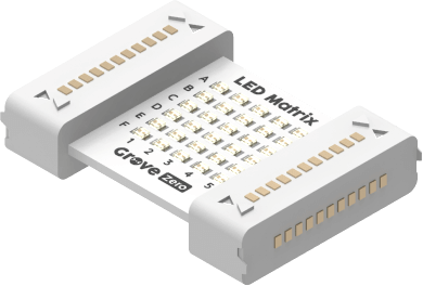
1) LED Matrix programming blocks
1.1)
This block controls LED Matrix to show various patterns.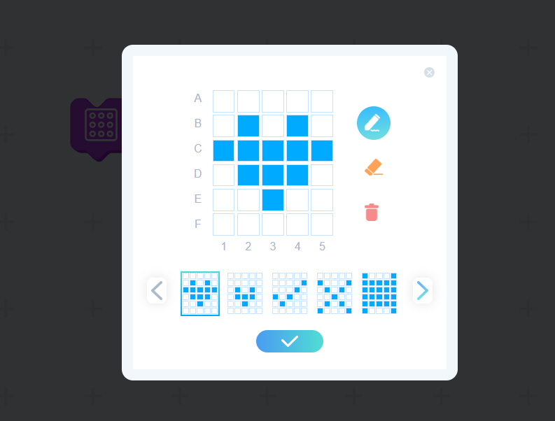
Click on the dropdown box, you can draw various patterns through moving the mouse and clicking the button. Also there are default 25 patterns in the bottom of the page for you to select.
Example 1: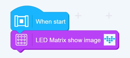
When start, the LED Matrix will show the image “heart”.
1.2)
This block controls the matrix to show the scrolling string. The string could be English words, numbers, number symbols and can be 31 characters maximum. If other characters are input in the blank, then it will show nothing.
Example 2: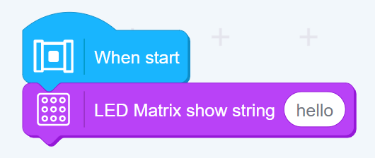
When start, the LED Matrix will show scrolling “hello”.
1.3)
Taking the top left of the LED Matrix as the origin of the axis (0,0), this block turns on LEDs at certain locations. (0≤x≤4, 0≤y≤5. If the number input is beyond the number range, then it will automatically turn to be a number within the range.)
Example 3: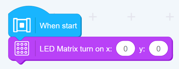
When start, the LED on the location of (0,0) will be on immediatelly.
1.4)
Taking the top left of the LED Matrix as the origin of the axis (0,0), this block turns off LEDs at certain locations. (0≤x≤4, 0≤y≤5. If the number input is beyond the number range, then it will automatically turn to be a number within the range.)
Example 4: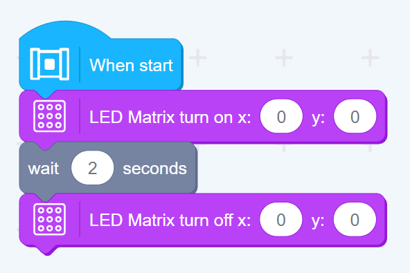
When start, LED on the location of (0,0) will be on immediatelly and then off after 2 seconds.
1.5)
This block controls all LEDs on the matrix to be off immediately.
Example 5: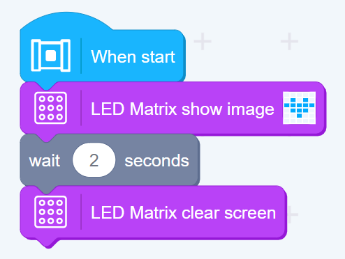
When start, LED Matrix shows the pattern “heart” and then clears screen in 2 seconds.
2) RGB LED programming blocks
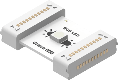
2.1)
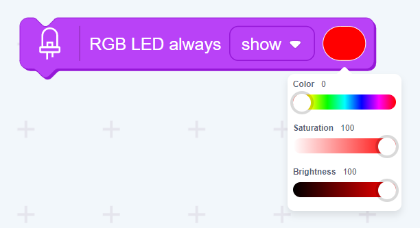
This controls LEDs to “show, blink, breath” and adapts their colors by changing the color, saturation and brightness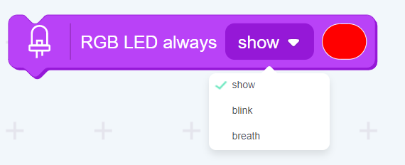
Example 6: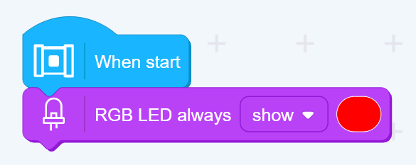
When start, RGB LEDs will always show red lights.
2.2)
This block controls RGB LEDs to show different lighting.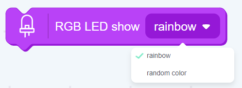
“rainbow”: colors change regularly; “random color”: show a color randomly.
Example 7: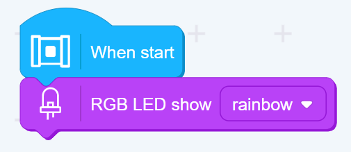
2.3)
This block controls LEDs to fade from a color to another.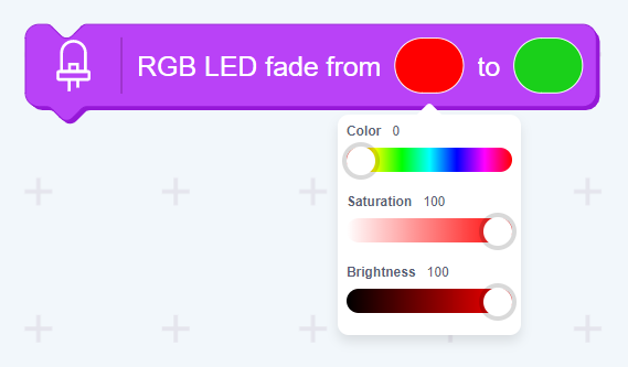
Click on the color lump to select different colors.
Example 8: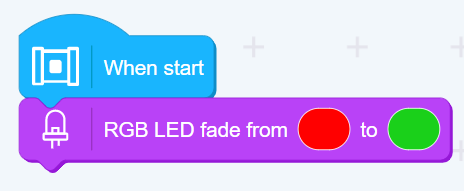
When start, RGB LEDs will fade from red to green.
2.4)
This block controls the brightness of RGB LEDs. The default brightness is 50%.
(The brightness input value is n where 0≤n≤100. If the number input is beyond the number range to input into the blanks, then it will automatically turn to be a number within the range.)
Example 9: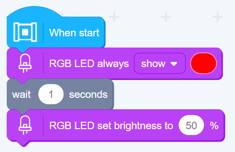
When start, RGB LEDs shows red and the brightness reduces to 10% in 2 seconds.
2.5)
This block controls RGB LEDs to be off.
Example 10: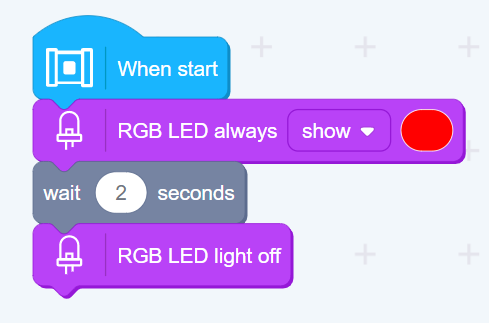
When start, RGB LEDs will be on for 2 seconds and then be off.
2.6)
This block precisely controls the numerical value of LEDs that will be on.
(the numerical value is n and 0≤n≤255. If the number input is beyond the number range, then it will automatically turn to be a number within the range.)
Example 11:
Here you can use 2.1) blocks to control the saturation and brightness.
2.7)
This block precisely controls the numerical value of RGB LEDs color, saturation and brightness.
(the numerical value is n and 0≤n≤255. If the input number is beyond the number range, then it will be automatically turned to be a number within the range.)
Example 12:
When start, RGB LEDs will show color 0, saturation 100 and brightness 100. (Red lights in the picture below)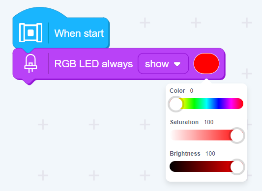
3) RGB LED Matrix programming blocks
3.1)
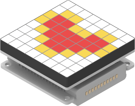
This block controls the RGB Matrix to show various images.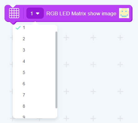
9 matrixes can be connected maximum.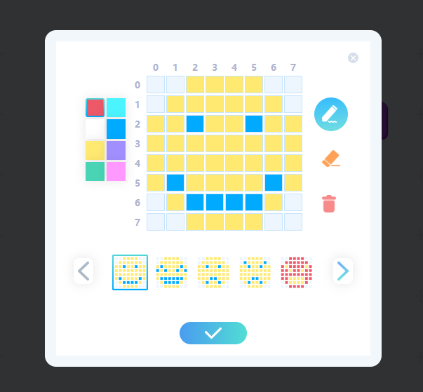
Click the dropdown box, you can then select default 35 patterns and also clear the patterns and select the color you want to draw an image.
Example 13: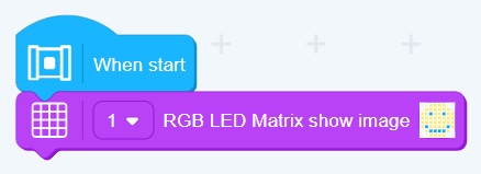
When start, the matrix will show a smiley image.
3.2)
This block controls the matrix to show the scrolling string that you input. The string could be English words, numbers, number symbols and can be 31 characters maximum. If other characters are input in the blank, then it will show nothing.
Example 14:
When start, the matrix will show scrolling “hello” once.
3.3)
This block controls the matrix to show an animation.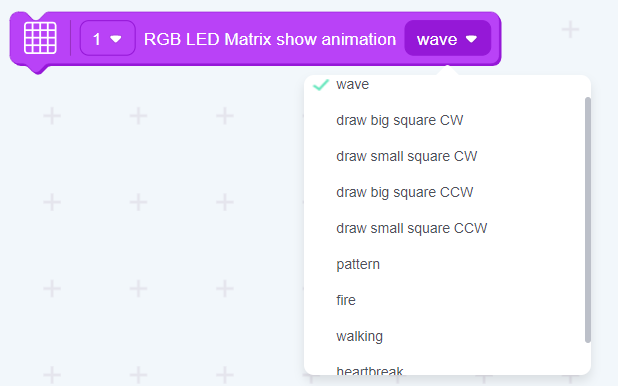
There are 9 default animations.
Example 15:
When start, the matrix will show the wave animation once.
3.4)
The bar plot value is an integer “n” and 0≤n≤32. If the number input is beyond the number range, then it will be automatically turned to be a number within the range. From 0 to 32, the bigger the numerical value is, the more lights will be on. Moreover, the lights will change from yellow to orange then to red.
Example 16:
3.5)
Taking the bottom left of the LED Matrix as the origin of the axis (0,0), this block turns on LEDs in certain coordinates. (0≤x≤7, 0≤y≤7. If the number input is beyond the number range, then it will be automatically turned to be a number within the range.)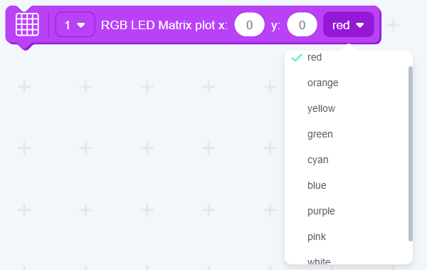
There are 9 colors of LEDs for you to select.
Example 17:
When start, the LED in the coordinate (0,0) will show red immediatelly.
3.6)
Taking the bottom left of the LED Matrix as the origin of the axis (0,0), this block turns off LEDs in certain coordinates. (0≤x≤7, 0≤y≤7. If the number input is beyond the number range, then it will be automatically turned to be a number within the range.)
Example 18: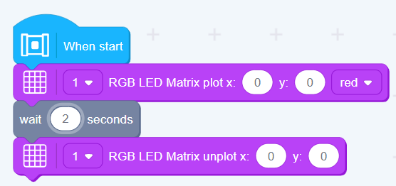
When start, the LED in the coordinate (0,0) will show red immediatelly and then be off in 2 seconds.
3.7)
This block controls RGB LEDs to be on or off. When a LED is on, then once Grove zero execute the block, the LED will be off and vice versa.
Example 19: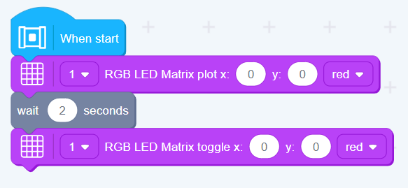
3.8)
This block is mainly used for logical judgements.
Example 20: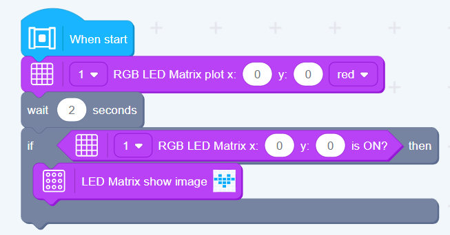
When start, LED in the coordinate (0,0) will be on automatically for 2 seconds. If the condition is met, then the matrix will show the image “heart”.
3.9)
This block controls all LEDs on the matrix to be off immediatelly.
Example 21: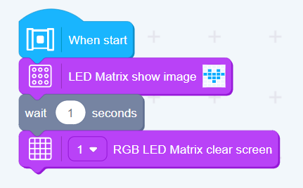
When start, the matrix will show the image “smiley” for 2 seconds and then all will be off.
3.10)
Example 22:
When start, the matrix will show the image “smiley” for 2 seconds. Then the matrix will show the scrolling color of the LED in the coordinate (0,0).
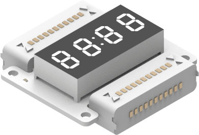
4) 4 Digit Display show 0
4.1)
This block controls the digit display to show an integer n and -999≤n≤9999. If the number input is beyond the number range, then it will automatically turn to be a number within the range.
Example 23: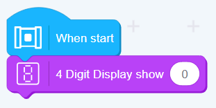
4.2)
This block controls the digit display to set a timer of “n” seconds and 0≤n≤9999. If the number input is beyond the number range to input into the blanks, then it will automatically turn to be a number within the range.
Example 24: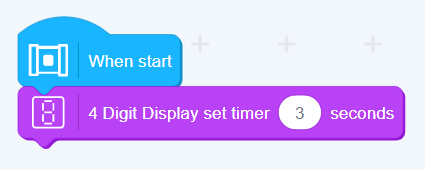
When start, the 4 digit display then will begin to count down 3 seconds.
4.3)
As the starting procedure programmming block, this block gives commands to the 4 digit display when the timer ends.
Example 25: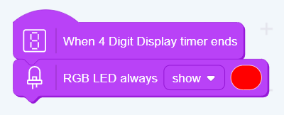
When start, the 4 digit display will begin to count down. When the timer ends, RGB LEDs will then show red lights.
4.4)
This block controls the 4 digit display to be off immediatelly.
Example 26: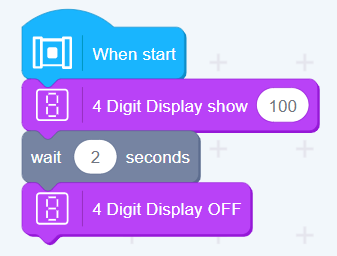
When start, the 4 digit display shows 100 and then will be off in 2 seconds.
4.5)
This block changes the brightness of the 4 digit display and its default brightness is 100%.
(The input value of the brightness is n and 0≤n≤100. If the number input is beyond the number range to input into the blanks, then it will automatically turn to be a number within the range.)
Example 27: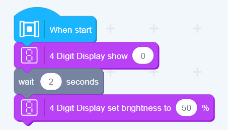
When start, the 4 digit display will show “0” with 100% brightness. After 2 seconds, the brightness will reduce to 50%.
5) Mech Key blocks
5.1)
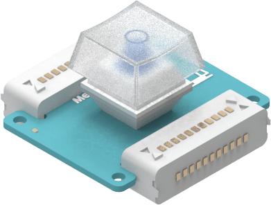
This programming block controls the color that LEDs will show when the mech key is pressed.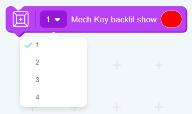
At most 4 Mech Keys are allowed to be connected simultaneously.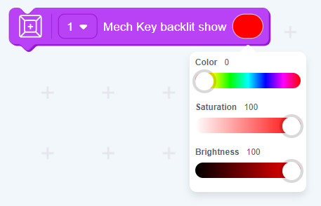
You can select the color you want through adapting the color, saturation and brightness.
Example 28: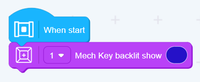
When start, blue lights will be on.
5.2)
This block controls the Mech Key built-in RGB LEDs to be off.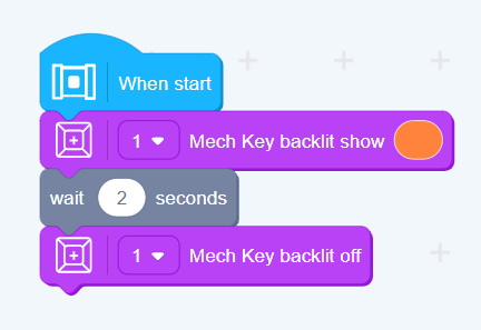
Example 29:
When start, the Mech Key built-in RGB LEDs will show orange lights for 2 seconds, then will be off.

