- I Introduction
- II Module Details
- III Programming Environment
- IV Tutorials
- 2. Rainbow Singer
- 3. Color Recognizer
- 4. Remote Control Car
- 4.1 Implementation
- 4.2 Write a Program
- 4.3 Connect a Device
- 【Note: We need 2 micro:bits in this project, one for sending the signals, the other for receiving the signals. So naturally, we have to write separate programs for each of the micro:bit.】
- 【Note: The extra micro:bit is not included in the Bit Kit.】
- 4.4 Download a Program
- 4.5 Run a Program
- V Course Materials
- VI Attachments
I Introduction
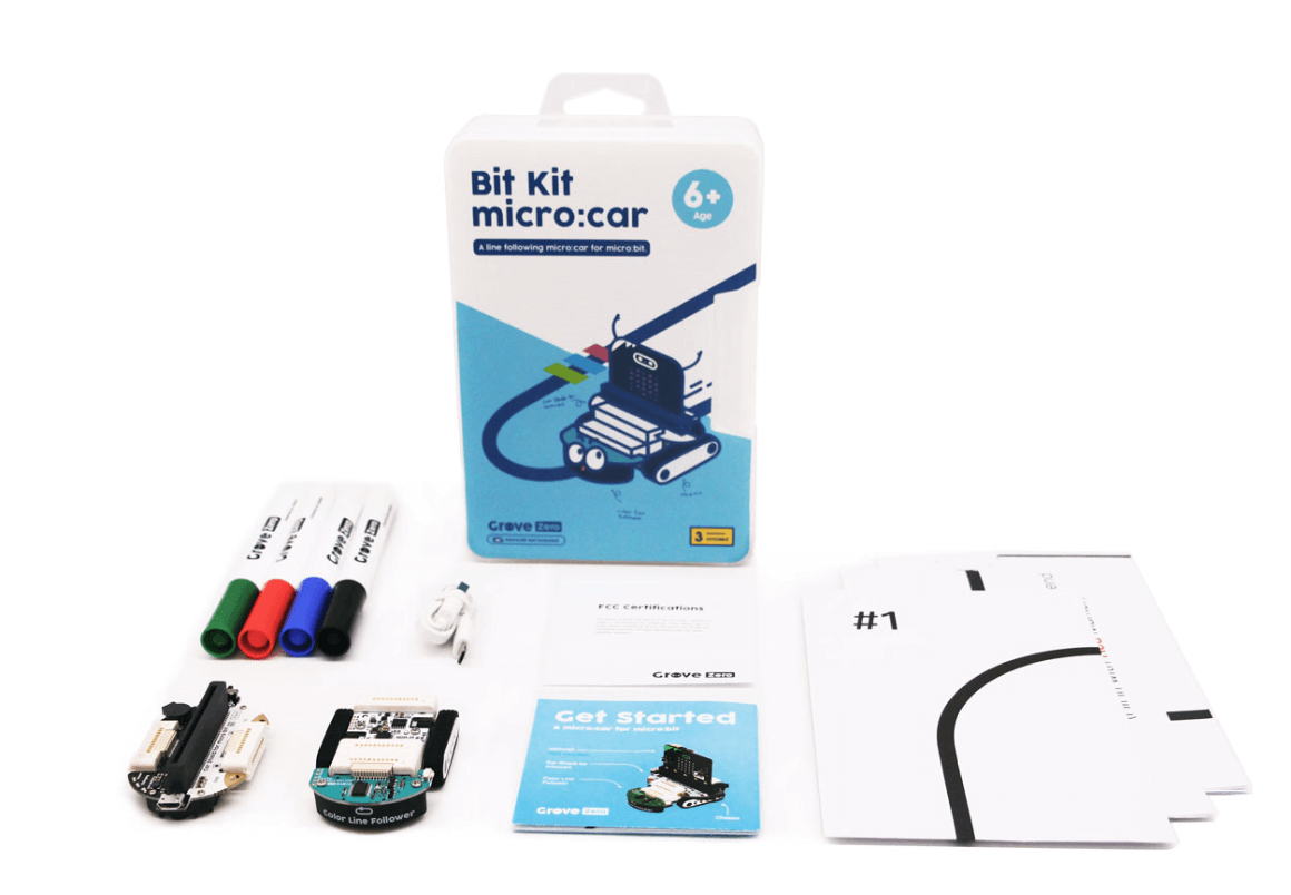
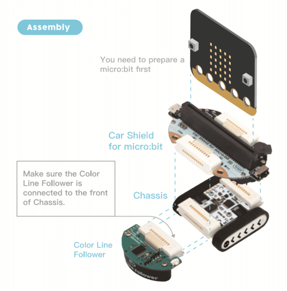
Bit Kit includes a micro:bit and other important Grove Zero modules to let you make a compact and cool car robot in a few seconds. Only using a magnetic snap together contacts, the micro:bit can be turned into a control board for Grove Zero modules, that is to say, without soldering or wires to tangle up, you can connect a servo or a sensor to the micro:bit through a simple magnetic snap!
The micro:bit shield itself also incorporates a buzzer, 4 addressable RGB LEDs and a chargeable lithium battery (190 mAh). You can use a 5V micro USB cable to charge the lithium battery.
Note: Only use the 5V micro USB cable for charging the lithium battery, not the micro:bit!
II Module Details
Items included in the kit are as follows: 1 color line follower, 1 chassis, 1 micro:bit expansion board, 1 USB cable, 1 game map, 4 markers and 1 User Guide. Below is an informative table about the specific module details. You can click one of the small images to see a large version of the modules, or click More Info to know more about them.
| Name | Image | Detail |
|---|---|---|
| Color Line Follower |  |
Using the built-in infrared LED, this sensor is able to detect a black track and recognize various colors on the ground. By connecting it to the chassis, you can get a cool, compact line following car. More Info |
| Chassis |  |
The chassis is composed of two electric motors to drive the wheels. Snapping some Grove Zero modules to it, a functional and fun car robot is ready for you. More Info |
| micro:bit Expansion Board |  |
It bridges the micro:bit with a series of Grove Zero modules to extend the functions of micro:bit. The expansion board incorporates a battery, a buzzer and 4 RGB LEDs, together with a GND and P2 connection ports same as that of the micro:bit. More Info |
III Programming Environment
1. MakeCode: Block-Based Editor for micro:bit
Let’s control the included Grove Zero modules with a micro:bit. We will first start by MakeCode – a graphical programming platform where we can implement a programmable micro:car by adding the Grove Zero extension to it.
How to Add Grove Zero Extension:
Go to MakeCode: https://makecode.microbit.org
- Step 1 Create a new project to enter the workspace. Click the gear icon (for settings) on the blue bar.
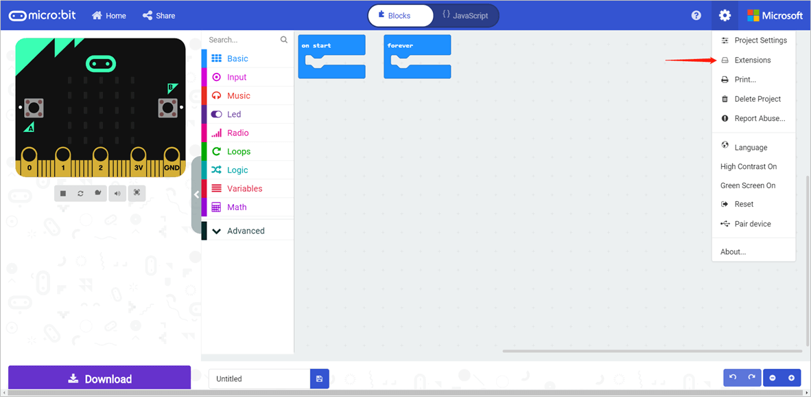
- Step 2 Select Extensions from the drop-down list which takes you to the extensions page.
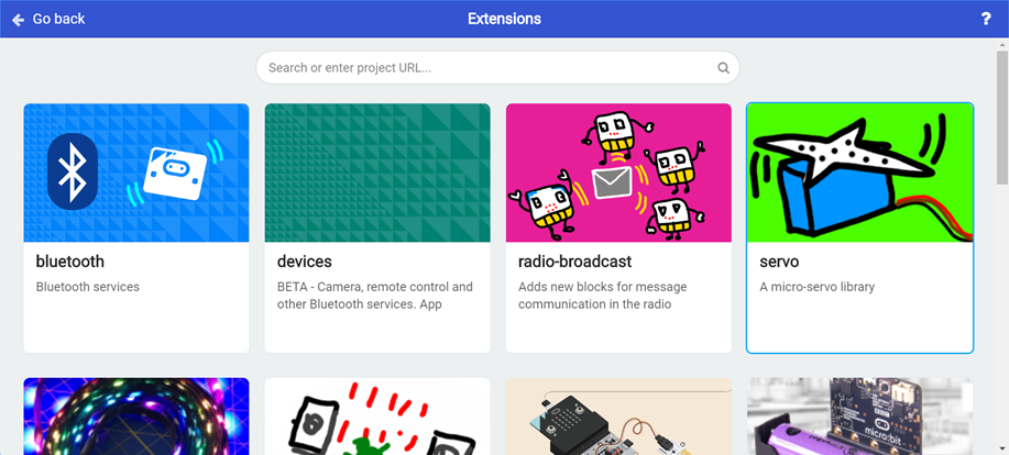
Step 3 Input grove zero into the search box. The extension package then pops up.
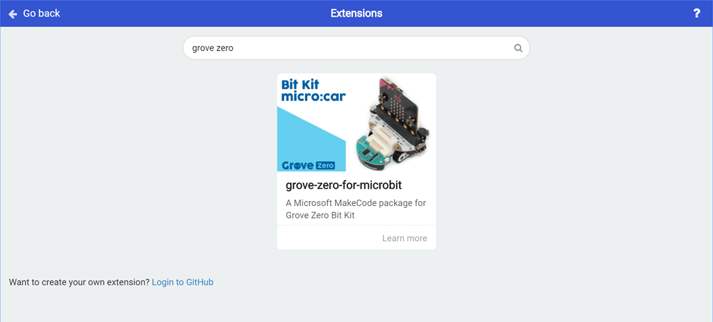
If it prompts that the extension does not exist, close the browser and enter MakeCode to try again.
Step 4 Click the extension package which takes you back to the workspace. You will see that the Grove Zero extension is then successfully added.
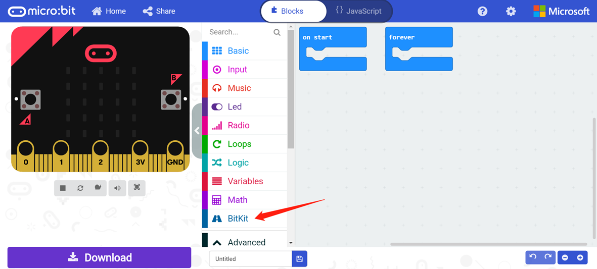
We can move on to programming after adding the extension.
2. Python Editor for micro:bit
If you want to program the micro:bit using a Python programming language, we can choose MicroPython. which is a version of Python that runs on the micro:bit and allows you to control the included Grove Zero modules easily. Let’s find out how to do it in the following instruction!
2.1 micro:bit Expansion Board
We use a neopixelmodule for controlling the four RGB LEDs (also known as WS2812 LEDs) built on the board. (Click here for specifics)
Example Program:
# light up the RGB LEDs on the Car Shield for micro:bitfrom microbit import *# the neopixel module lets you use Neopixel (WS2812) individually addressable RGB LED strips with the Microbit. Note to use the neopixel module, you need to import it separately with:import neopixel# setup the RGB LEDs on pin1 with a length of 4 pixelsnp = neopixel.NeoPixel(pin1, 4)# turn on and off the LEDs to red every 2 secondswhile True:np[0] = (255, 0, 0) # Set RGB LED 1 to full brightness rednp[1] = (255, 0, 0) # Set RGB LED 2 to full brightness rednp[2] = (255, 0, 0) # Set RGB LED 3 to full brightness rednp[3] = (255, 0, 0) # Set RGB LED 4 to full brightness rednp.show() # Push the colour data to LEDssleep(2000) # wait for 2 secondsnp.clear() # Clear all the LEDssleep(2000)
For controlling the buzzer, we use a music module.(Click here for specifics)
Example Program:
# light up the RGB LEDs on the Car Shield for micro:bitfrom microbit import *# import the music module to control buzzerimport music# make buzzer play melody 'nyan'music.play(music.NYAN)
2.2 Chassis
A i2c.write method in the I2C module are used to control the chassis. (Click here for specifics)
Example Program:
# control Chassisfrom microbit import *# the addressed of chassischassis_addr = 0x28# set the control mode, make sure it's set to 1mode = 0x01# set the direction of motor, 0x00 is moving forward while 0xff is moving backwardleft_motor_direction = 0x00right_motor_direction = 0xff# set the speed of motors, note that when moving backward, the actual speed is 255 - (speed you set), so the full speed for moving backward is 0x00left_motor_speed = 0xffright_motor_speed = 0x00# define the command that needs to be sent to chassiscmd = bytearray([mode, left_motor_speed, left_motor_direction, right_motor_speed, right_motor_direction])# Re-initialize peripheral with the specified clock frequency freq on the specified sda and scl pinsi2c.init(freq=100000, sda=pin20, scl=pin19)# send the command to chassis via i2c bus protocoli2c.write(chassis_addr, cmd, repeat=False)
2.3 Color Line Follower
In order to detect a black line or lines in other colors using the color line follower, we use a i2c.write and i2c.read method in the I2C module to help.
Example of Color Detection
# get the color event from Color Line Followerfrom microbit import *# the addressed of Color Line Followerline_follower_addr = 0x27# Re-initialize peripheral with the specified clock frequency freq on the specified sda and scl pinsi2c.init(freq=100000, sda=pin20, scl=pin19)while True:# every time before you read the sensor data, you need to set the mode# mode: b'\x01' - get color event# mode: b'\x02' - get line event# mode: b'\x04' - get the color value in R,G,Bi2c.write(line_follower_addr, b'\x01', repeat=False)# read 4 bytes from the sensor, the value of first byte indicates the color that is being detected# 1: Black, 2: Red, 3: Green, 4: Blue, 5: Other colort = i2c.read(line_follower_addr, 4)# display the value of first byte on LED screendisplay.show(t[0])sleep(50)
Example of Black Line Detection
# get the line position from Color Line Followerfrom microbit import *# the addressed of Color Line Followerline_follower_addr = 0x27# Re-initialize peripheral with the specified clock frequency freq on the specified sda and scl pinsi2c.init(freq=100000, sda=pin20, scl=pin19)while True:# every time before you read the sensor data, you need to set the mode# mode: b'\x01' - get color event# mode: b'\x02' - get line event# mode: b'\x04' - get the color value in R,G,Bi2c.write(line_follower_addr, b'\x02', repeat=False)# read 1 byte from the sensor, the value indicates the detected line position# 1: middle, 2: no line detected, 3: left, 4: leftmost, 5: right, 6: rightmostt = i2c.read(line_follower_addr, 1)# display the sensor value on the screendisplay.show(t[0])sleep(50)
Example of Getting the RGB Value
# get the color event from Color Line Followerfrom microbit import *# the addressed of Color Line Followerline_follower_addr = 0x27# Re-initialize peripheral with the specified clock frequency freq on the specified sda and scl pinsi2c.init(freq=100000, sda=pin20, scl=pin19)while True:# every time before you read the sensor data, you need to set the mode# mode: b'\x01' - get color event# mode: b'\x02' - get line event# mode: b'\x04' - get the color value in R,G,Bi2c.write(line_follower_addr, b'\x04', repeat=False)# read 4 bytes from the sensor# each byte indicates - blue, green, red, 0t = i2c.read(line_follower_addr, 4)# display the sensor value on the screendisplay.scroll(t[0]) # color value of bluesleep(1000);display.scroll(t[1]) # color value of greensleep(1000);display.scroll(t[2]) # color value of redsleep(1000);display.scroll(t[3]) # return 0sleep(1000);
IV Tutorials
1. Line Following Car
1.1 Implementation
The car will drive along a black line after turning on.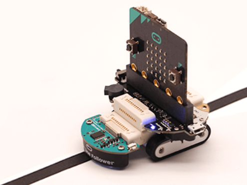
1.2 Write a Program
First, add the Grove Zero extension.
Drag and drop a forever block. This program is going to perform decision making 5 times, that means, 5 conditional statements will be nested in the forever block.
Then, follow this program logic to connect the blocks together:
If the color line follower sees a black line right ahead of it, the car will go forward at a medium speed;
If the color line follower sees a black line on the far left, the car will turn left at a fast speed;
If the color line follower sees a black line on the left, the car will turn left at a medium speed;
If the color line follower sees a black line on the right, the car will turn right at a medium speed;
If the color line follower sees a black line on the far right, the car will turn right at a fast speed;
When none of the cases above happen, the car will stop.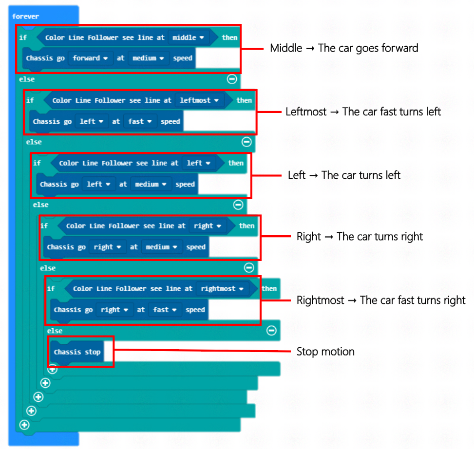
1.3 Connect a Device
Snap the mainboard, expansion board, chassis and color line follower together. Check if the LED indicator on the micro:bit lights up. If not, the USB cable may be connected incorrectly.
1.4 Download a Program
We have described how to download your micro:bit programs in previous tutorials. You just need to rename your program, click the “Download” button and send it to your micro:bit.
1.5 Run a Program
Turn on the switch on the micro:bit expansion board and see if the program can run normally.
2. Rainbow Singer
2.1 Implementation
The car will play beautiful melodies as it drives along a colorful track.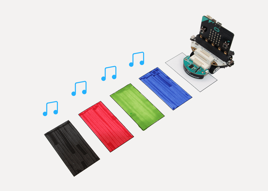
2.2 Write a Program
First thing first, we need to add a Grove Zero extension.
Drag and drop a forever block. This car will firstly drive slowly and the buzzer should be silent.
Next, the program will perform decision making 3 times, which follows a program logic like this:
If the color line follower detects red, the buzzer will play a tone Middle C and pause for 1 second;
If the color line follower detects green, the buzzer will play a tone High D and pause for 1 second;
If the color line follower detects blue, the buzzer will play a tone Low F and pause for 1 second;
If the color line follower detects black, the buzzer will play a tone High A and pause for 1 second.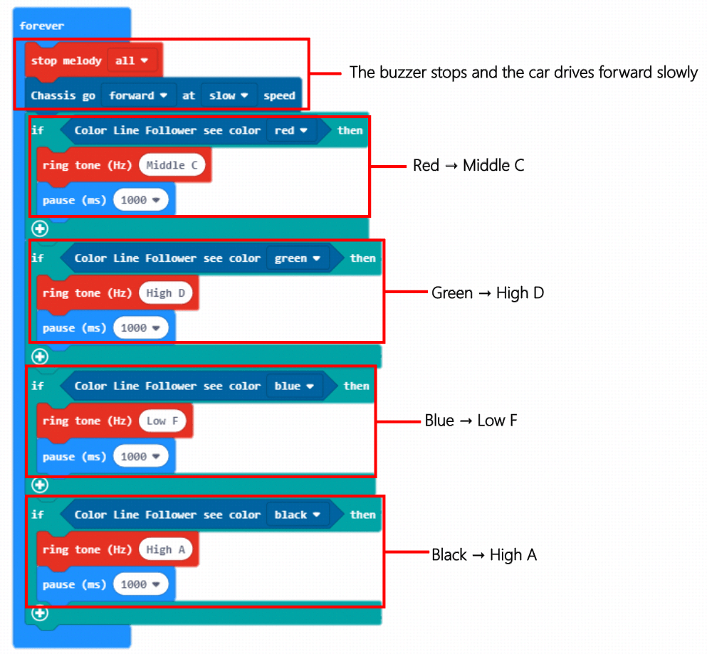
2.3 Connect a Device
Snap the mainboard, expansion board, chassis and color line follower together. Check if the LED indicator on the micro:bit lights up. If not, the USB cable may be connected incorrectly.
2.4 Download a Program
We have described how to download your micro:bit programs in previous tutorials. You just need to rename your program, click the “Download” button and send it to your micro:bit.
2.5 Run a Program
Turn on the switch on the micro:bit expansion board and see if the program can run normally.
3. Color Recognizer
3.1 Implementation
The car will first drive along a black line. But when it sees different colors, it will react to them differently.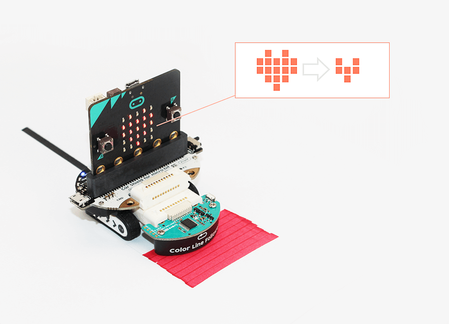
3.2 Write a Program
Still, let’s add the Grove Zero extension first. Then add a forever block.
In the next step, we will determine what icons and melodies the micro:bit will show and play when the car sees different colors. The program logic will be like:
When seeing a green color, the car shows a big heart icon and plays dadadum;
When seeing a blue color, the car shows a smiley face and plays birthday;
When seeing a red color, the car shows a sad face and plays blues.
For the second part of our program, we will repeat what we have learned in Tutorial 1 already – make the car follow a black line. So let’s just go through those steps again and work on the blocks.
As soon as all the blocks are ready, our program completes.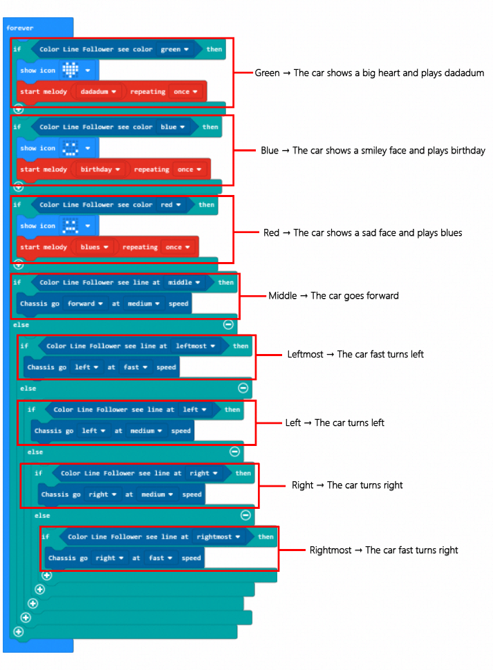
3.3 Connect a Device
Snap the mainboard, expansion board, chassis and color line follower together. Check if the LED indicator on the micro:bit lights up. If not, the USB cable may be connected incorrectly.
3.4 Download a Program
We have described how to download your micro:bit programs in previous tutorials. You just need to rename your program, click the “Download” button and send it to your micro:bit.
3.5 Run a Program
Turn on the switch on the micro:bit expansion board and see if the program can run normally.
4. Remote Control Car
4.1 Implementation
We will use one micro:bit to control the car and one micro:bit as the controller. When the button A is pressed, the car will drive fast forward. When the button B is pressed, it will drive fast backward.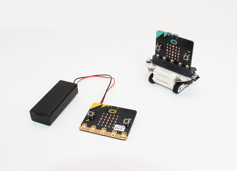
4.2 Write a Program
As usual, add the Grove Zero extension.
Let’s program the car first.
Add an on start block. Set the radio group number as 1.
Next, add a forever block. Follow this program logic: if the button A is pressed, the radio sends the number 11; if the button B is pressed, the radio sends the number 22.
Then, let’s program the controller micro:bit.
Add an on start block. Set the radio group number as 1. If the radio receives a number 11, the car goes fast forward; if the radio receives a number 22, the car goes fast backward.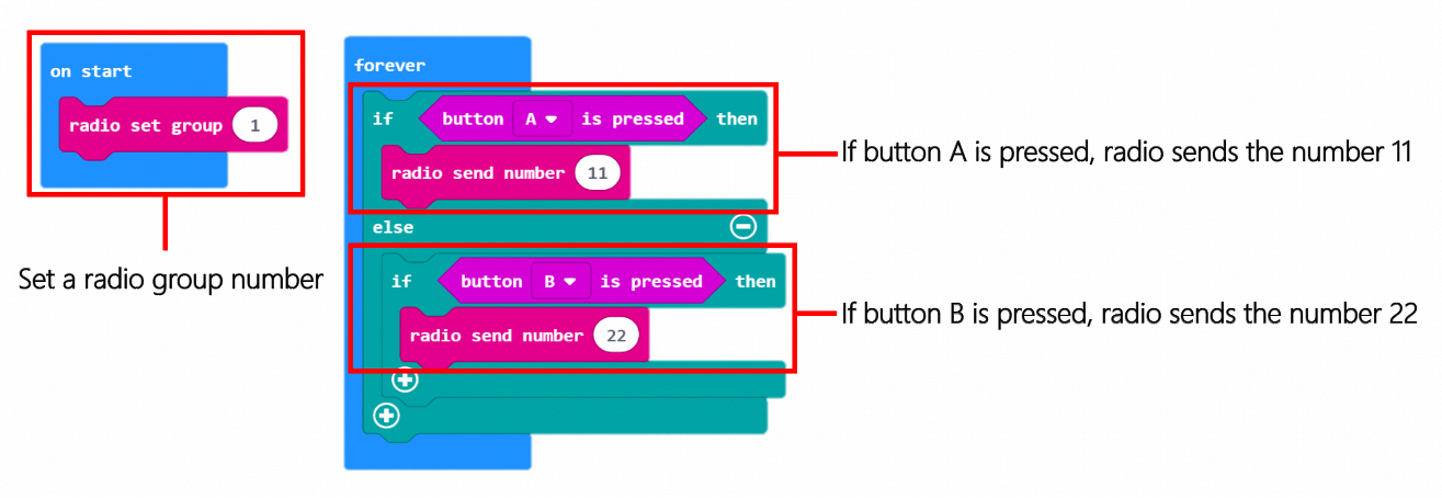
Program for the Controller

4.3 Connect a Device
Snap the mainboard, expansion board, chassis and color line follower together. Check if the LED indicator on the micro:bit lights up. If not, the USB cable may be connected incorrectly.
【Note: We need 2 micro:bits in this project, one for sending the signals, the other for receiving the signals. So naturally, we have to write separate programs for each of the micro:bit.】
【Note: The extra micro:bit is not included in the Bit Kit.】
4.4 Download a Program
We have described how to download your micro:bit programs in previous tutorials. You just need to rename your program, click the “Download” button and send it to your micro:bit.
4.5 Run a Program
Turn on the switch on the micro:bit expansion board and see if the program can run normally.
V Course Materials
You can see related course materials about the Bit Kit and micro:bit on our online learning platform Make2Learn via this address: https://make2learn.tinkergen.com/
VI Attachments
Attachment 1: Bit Kit Tutorial Source Code
Attachment 2: Bit Kit Map

若有收获,就点个赞吧
0 人点赞
