Smart Home Security Camera System - Hackster.io

Hi! Please confirm your email address by clicking the link in the email we sent you. Haven’t received it? Resend confirmation email
×
1
Notifications
ProjectsProjectsNewsContestsEventsVideosWorkshopsLaunch
×
Embed the widget on your own site
Add the following snippet to your HTML:
[

Cost-effective camera system using a single PTZ IP camera to monitor 3 separate zones using PIR sensors to pan camera.
Read up about this project on “Smart Home Security Camera System”)
Smart Home Security Camera System
18 6,226
18
![]()
Published October 6, 2017 © GPL3+
Smart Home Security Camera System
Cost-effective camera system using a single PTZ IP camera to monitor 3 separate zones using PIR sensors to pan camera.
IntermediateFull instructions provided12 hours6,336
[
![]()
5th - 16th
ESP8266 IoT Contest - Simplify the Connected World
](/contests/ESP8266#category-224)
[
](https://www.hackster.io/contests/UNDPCOVID19)
Join the COVID-19 Detect and Protect Challenge to help flatten the curve!
Things used in this project
Hardware components

SparkFun ESP8266 Thing - Dev Board
×
1
SparkFun - SparkFun ESP8266 Thing - Board
×
1

SparkFun FTDI Basic Breakout - 3.3V
×
1
HC-SR501 PIR Motion Sensor Module
×
2

×
1
Red Laser 5mW 3-5V
×
1
CDS Photocell
×
2
FDT FD7903 Outdoor PTZ IP Camera
×
1
2n3904 NPN Transistor
×
1
Resistor 1K Ohm
×
1
Resistor 10 Ohm
×
2
Software apps and online services


Omxplayer
Linux Screen manager
Story
Introduction and Motivation
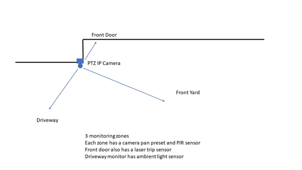
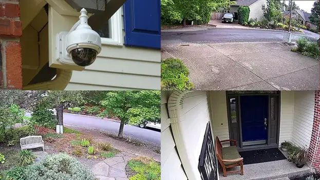
I wanted to monitor activity at the front of my house without the expense of multiple cameras. My project uses a single PTZ IP camera that pans to provide wide area coverage. I have 3 areas that need to be covered, the front yard and the driveway (looking away from the house) and the front door (looking toward the house). I use a PIR sensor and a Sparkfun 8266 board for each zone to detect motion and cause the camera to pan to that zone.
The Cayenne IOT Platform provides the ideal interface to integrate the various functions and to provide dashboard displays in both a web browser and on a mobile app.
Project Overview
Dedicated Camera Display Monitor
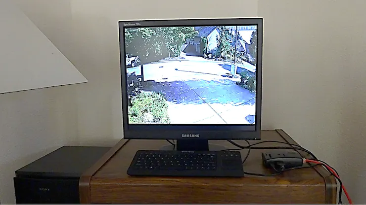
I wanted to have a “live” display of the camera image in my living room for continuous monitoring. I used an old 20” Samsung LCD monitor with a Raspberry Pi to implement that. The Pi is running Omxplayer to display a live stream from the camera.
Sensors
I won a Sparkfun 8266 Thing Dev from the idea phase of this contest. I decided for the purposes of the contest that I would only implement 2 of the 3 zones as proof of concept (I will finish the third zone when I have more time). I will use the 8266 Thing Dev for one zone sensor and I bought an additional 8266 Thing for the second zone sensor.
I am using HC-SR501 modules for PIR detection.
I built a trip wire sensor using a generic 5V 5mW red laser and a generic CDS photocell.
I am using a generic CDS photocell for ambient light detection.
Camera
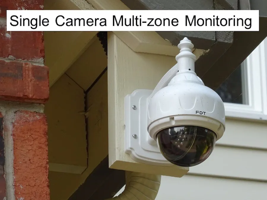
I am using an FDT FD7903 Outdoor HD PTZ IP camera. It has WiFi capability but I am using it with hardwired ethernet for reliability. The network interface to my Pi is also wired. The camera has a built in web server that I can use to pan and record snapshots and video.
Software
I am using the Arduino IDE to program 8266 Thing/Dev boards. It is using the Cayenne MQTTESP8266 library to implement the Cayenne interface.
I am using Cayenne IOT Platform to perform device control/monitoring and inter-device triggering.
Building the Project
Step 1: Setup the PTZ camera.
I needed to find a place to mount the camera that would allow it cover all 3 zones. The camera would need to cover a 270 degree field of view. I had a point at the corner of my garage that I could use, but I needed to build an extension to allow the camera to mount below the gutter downspout.
IP Camera, Driveway, Front Yard and Front Door zones
Step 2: Setup the dedicated display
I used an old Samsung 1280x1024 LCD monitor and a Raspberry Pi 3 to implement the display. Since it was an older monitor I needed to use a VGA to HDMI adapter to connect to the Pi.
I am running a standard Raspbian Jessie OS on the Pi. I needed to add the Omxplayer and Screen software to allow viewing the RTSP stream from the camera.
Install Omxplayer:
Install dependencies:
sudo apt-get install libpcre3-dev libpcrecpp0 libva-dev libva-x11-1 libva1
Download package and unzip:
wget http://seyrsnys.myzen.co.uk/rpi/omxplayer_0.0.1-arm.deb
Install package:
sudo dpkg -i omxplayer_0.0.1-arm.deb
Install Screen:
sudo apt-get install screen
Create shell script to view rtsp stream:
Bash script is named driveway (name of the camera) – see code section
Step 3: Build the PIR Modules
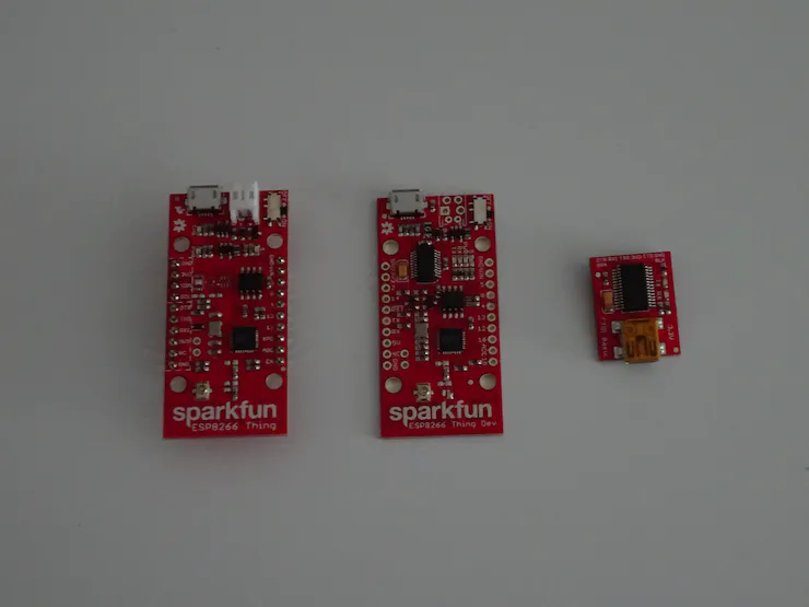
ESP8266 Thing, ESP8266 Thing Dev, FTDI Basic 3.3V
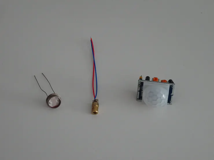
CDS photocell, 5mW laser, PIR detector
Front door Module Breadboard
Front Door Module:
I used the ESP8266 Thing for the Front door module. It is similar to the Thing Dev board but it does not have an onboard FTDI interface so I needed to use a 3.3V FTDI Basic board to program it. It does have capability to use and charge a LiPo battery so I may use this board to implement my final configuration. It depends the final average power consumption. Currently I am using generic USB power banks to power the modules.
Laser trip wire sensor:
I mounted the laser in a used ball point pen casing and put that into some PVC sprinkler adapters. I also mounted the CDS photocell into sprinkler adapters to shield it from ambient light. The adapters allowed me to align the laser and photocell. I used an NPN transistor to provide the current drive for the laser. The photocell resistance was between 40-50 ohms under full intensity so I used with a 10 ohm resistor to keep the output voltage within the 1V range of the A/D converter of the ESP8266. See schematic for hookup details.
PIR sensor:
The sensor has two trim pots for sensitivity and trigger delay. I set them to maximum sensitivity and minimum delay (2-3 seconds). There is also a mode jumper that I set to re-trigger.
Driveway Module Breadboard
Driveway Module:
I used the ESP8266 Thing Dev for the Driveway module. It does have an onboard FTDI interface so it can be programmed directly via USB.
Ambient light sensor:
I used a CDS photocell mounted on a bottle cap as my ambient light sensor (basically used to determine if it is day or night). I used it in the same configuration as the one in the laser circuit.
PIR sensor:
This is hooked up identically to the one on the Front door module.
Step 4: Write the ESP8266 Code and upload
I started with the Cayenne ESP8266.ino example program from github: https://github.com/myDevicesIoT/Cayenne-MQTT-ESP8266/blob/master/examples/ESP8266/ESP8266.ino
You need to put in Cayenne device identifiers that you get when you create your device. From the Cayenne dashboard add a new Sparkfun ESP8266 Thing Dev Board and copy the following strings into the code: MQTT Username, MQTT Password and Client ID.
Add the SSID and password of your WiFi network.
Add the device logic and widget code (see the .ino files in the code section).
Step 5: Configure the Cayenne Interface
Next step is to add the widgets to the dashboard and create the triggers. The 2 device dashboards are shown below and also the trigger that is used to pan the camera when motion is detected by the PIR sensor.

Thing Dashboard (Front door zone)

Thing Dev Dashboard (Driveway zone)

Trigger on PIR Detect
Step 6: Test the system
Next Steps:
I have not implemented the third zone, but I realized that the decision logic to control the cameras must be more complex. I need to be able to determine what to do if motion is detected in multiple zones simultaneously (need a priority scheme and inter-zone logic). I know that the Cayenne team is working on enhancing the Trigger capability (possibly adding combinatorial logic). I would also like to have the camera send snapshots. I don’t know if the camera widget in Cayenne will handle that when it is implemented or if I will need to use the camera webserver to do that.
I have been very happy with the ease of implementation using the Sparkfun ESP8266 hardware. Their tutorials are also great. I am somewhat concerned about how successful I will be in using battery power for these devices. I guess I will know soon.
Schematics
Front Door Module Breadboard

Front Door Module Schematic

Driveway Module Breadboard

Driveway Module Schematic

Code
PIR-ESP8266ThingCayenne.ino
Arduino
Code for Front Door Module
// This example shows how to connect to Cayenne using an ESP8266 and send/receive sample data. // Make sure you install the ESP8266 Board Package via the Arduino IDE Board Manager and select the correct ESP8266 board before compiling. //#define CAYENNE_DEBUG #define CAM_ENABLE //#define PAN_RESET #define CAYENNE_PRINT Serial #include
pinMode(ledPin, OUTPUT); //LED indication of Pan signal pinMode(laserPin, OUTPUT); //Laser pinMode(pirPin, INPUT); //PIR signal Serial.begin(9600); Cayenne.begin(username, password, clientID, ssid, wifiPassword); } void loop() {
Cayenne.loop(); lastMillis = millis(); valPIR = digitalRead(pirPin); valTrip = analogRead(A0); //Write data to Cayenne here if(valPIR && !firstTrig) { trigPIR = true; firstTrig = true; trigTime = millis(); } else { trigPIR = false; } if(!trigPIR && firstTrig && ((millis() - trigTime)/1000) > 20) { trigTime = 0; firstTrig = false; Cayenne.virtualWrite(resetpanCh, 1, “digital_sensor”, “d”); //reset Pan after 20 seconds if no motion } else { Cayenne.virtualWrite(resetpanCh, 0, “digital_sensor”, “d”); //do not reset Pan } Cayenne.virtualWrite(uptimeCh, lastMillis/1000); //uptime in seconds Cayenne.virtualWrite(pirCh, valPIR, “digital_sensor”, “d”); Cayenne.virtualWrite(tripCh, valTrip, “analog_sensor”, “null”); //trip photocell value } //Default function for processing actuator commands from the Cayenne Dashboard. CAYENNE_IN(presetpanCh) {
//CAYENNE_LOG(“CAYENNE_IN_DEFAULT(%u) - %s, %s”, request.channel, getValue.getId(), getValue.asString()); int i = getValue.asInt(); digitalWrite(ledPin, !i); #ifdef CAM_ENABLE
WiFiClient client; Serial.printf(“\n[Connecting to %s … “, host); if (client.connect(host, 80)) { Serial.println(“connected]”); Serial.println(“[Sending a request]”); if (i) { client.print(String (“GET /“) + “/cgi-bin/param.cgi?cmd=preset&-act=goto&-number=1 HTTP/1.1\r\n” + “Host: “ + host + “\r\n” + “Connection: close\r\n” + “Authorization: Basic XXXXX\r\n” + “\r\n” ); Serial.println(“[Response:]”); } else { client.print(String (“GET /“) + “/cgi-bin/param.cgi?cmd=preset&-act=goto&-number=0 HTTP/1.1\r\n” + “Host: “ + host + “\r\n” + “Connection: close\r\n” + “Authorization: Basic XXXXX\r\n” + “\r\n” ); Serial.println(“[Response:]”); } while (client.connected()) { if (client.available()) { String line = client.readStringUntil(‘\n’); Serial.println(line); } } client.stop(); Serial.println(“\n[Disconnected]”); } else { Serial.println(“connection failed!]”); client.stop(); } delay(5000); #endif } CAYENNE_IN(laserCh) {
//CAYENNE_LOG(“CAYENNE_IN_DEFAULT(%u) - %s, %s”, request.channel, getValue.getId(), getValue.asString()); int i = getValue.asInt(); digitalWrite(13, i); Serial.print(“Laser “); if(i) { Serial.println(“On”); } else { Serial.println(“Off”); } }
PIR-ESP8266ThingDevCayenne.ino
Arduino
Code for Driveway Module
// This example shows how to connect to Cayenne using an ESP8266 and send/receive sample data. // Make sure you install the ESP8266 Board Package via the Arduino IDE Board Manager and select the correct ESP8266 board before compiling. //#define CAYENNE_DEBUG #define CAM_ENABLE //#define PAN_RESET #define CAYENNE_PRINT Serial #include
pinMode(ledPin, OUTPUT); //LED pinMode(pirPin, INPUT); //PIR signal pinMode(A0, INPUT); //Ambient light photocell connected to AtoD Serial.begin(9600); Cayenne.begin(username, password, clientID, ssid, wifiPassword); } void loop() { Cayenne.loop(); lastMillis = millis(); valPIR = digitalRead(pirPin); valAtoD = analogRead(A0); #ifdef CAYENNE_DEBUG //output values to serial monitor if debug
Serial.print(“valPIR: “); Serial.println(valPIR); Serial.print(“valAtoD: “); Serial.println(valAtoD); #endif
//Write data to Cayenne here if(valPIR && !firstTrig) { trigPIR = true; firstTrig = true; trigTime = millis(); } else { trigPIR = false; } if(!trigPIR && firstTrig && ((millis() - trigTime)/1000) > 20) { trigTime = 0; firstTrig = false; Cayenne.virtualWrite(resetpanCh, 1, “digital_sensor”, “d”); //reset Pan after 20 seconds if no motion } else { Cayenne.virtualWrite(resetpanCh, 0, “digital_sensor”, “d”); //do not reset Pan } Cayenne.virtualWrite(uptimeCh, lastMillis/1000); //uptime in seconds Cayenne.virtualWrite(pirCh, valPIR, “digital_sensor”, “d”); //PIR detect signal Cayenne.virtualWrite(ambCh, valAtoD, “analog_sensor”, “null”); //Ambient light } //Default function for processing actuator commands from the Cayenne Dashboard. //You can also use functions for specific channels, e.g CAYENNE_IN(1) for channel 1 commands. CAYENNE_IN(presetpanCh) { //turn on blue LED in response to trigger CAYENNE_LOG(“CAYENNE_IN_DEFAULT(%u) - %s, %s”, request.channel, getValue.getId(), getValue.asString()); //Process message here. If there is an error set an error message using getValue.setError(), e.g getValue.setError(“Error message”); int i = getValue.asInt(); digitalWrite(ledPin, !i); #ifdef CAM_ENABLE
WiFiClient client; Serial.printf(“\n[Connecting to %s … “, host); if (client.connect(host, 80)) { Serial.println(“connected]”); Serial.println(“[Sending a request]”); if (i) { client.print(String (“GET /“) + “/cgi-bin/param.cgi?cmd=preset&-act=goto&-number=0 HTTP/1.1\r\n” + “Host: “ + host + “\r\n” + “Connection: close\r\n” + “Authorization: Basic XXXXX\r\n” + “\r\n” ); Serial.println(“[Response:]”); } else { client.print(String (“GET /“) + “/cgi-bin/param.cgi?cmd=preset&-act=goto&-number=1 HTTP/1.1\r\n” + “Host: “ + host + “\r\n” + “Connection: close\r\n” + “Authorization: Basic XXXXX\r\n” + “\r\n” ); Serial.println(“[Response:]”); } while (client.connected()) { if (client.available()) { String line = client.readStringUntil(‘\n’); Serial.println(line); } } client.stop(); Serial.println(“\n[Disconnected]”); } else { Serial.println(“connection failed!]”); client.stop(); } delay(5000); #endif }
driveway
ActionScript
bash script to display camera rtsp stream on Raspberry Pi display
!/bin/bash if !(screen -list | grep -q “driveway”) then screen -dmS driveway sh -c ‘omxplayer —win “0 32 1280 992” rtsp://admin:xxxx@x.x.x.x:554/12 —live’ fi
Credits
Ralph Yamamoto
2 projects • 6 followers
Comments
Please confirm your email before commenting. Haven’t received a confirmation email? Resend. Contact us at help@hackster.io for help.
Start the conversation!
[

](https://www.hackster.io/contests/UNDPCOVID19)
Join the COVID-19 Detect and Protect Challenge to help flatten the curve!
Awards
[
![]()
5th - 16th
ESP8266 IoT Contest - Simplify the Connected World
](/contests/ESP8266#category-224)
Related channels and tags
Related projects
[

](/NikunjME/raspberry-pi-security-camera-system-with-notification-b39d00)Raspberry Pi Security Camera System with Notification
[
](/hackershack/smart-security-camera-90d7bd)Smart Security Camera
[
](/ujur007/raspberry-pi-home-security-system-with-camera-and-pir-sensor-6154f3)Raspberry Pi Home Security System with Camera and PIR Sensor
[

](/amir-pournasserian/wireless-security-camera-system-with-raspberry-pi-android-981bcd)Wireless Security Camera System with Raspberry Pi & Android
[
](/amrmostaafaa/security-system-using-arduino-bluetooth-camera-616c4d)Security System Using Arduino Bluetooth Camera
Similar projects you might like
[

Automatic arming/disarming. Motion detection. Mobile notifications with images.
](/FutureSharks/raspberry-pi-security-system-with-motion-detection-camera-bed172)
Raspberry Pi Security System With Motion Detection / Camera
14176K
[
Build your homemade Smart security system with an old smartphone and an old webcam, all for less than $50.
](/naran-inc/diy-smart-home-security-system-for-50767d)
DIY Smart Home Security System For
2112K
[

A camera that describes your pictures to you instead of just showing them.
](/cchannon/raspberry-pi-smart-camera-a8c786)
4810K
[

Ever wondered what happens at home while you are away? Monitor your house for any motion and get notified of any movement.
](/riggaroo/smart-motion-sensing-camera-with-intruder-notifications-b6c613)
Smart Motion Sensing Camera with Intruder Notifications
469.8K
[
Sony Spresense Board + NodeMCU + Google Firebase + Android Studio
](/hivwolf/home-security-system-4c44d7)
234.4K
[
We built a smart home automation and security system using our lovely 1Sheeld board and some sensors and some cool stuff.
](/sadee/smart-home-automation-and-security-system-using-1sheeld-da7ce2)
Smart Home Automation And Security System Using 1Sheeld
Team SADEE
3110K
[
Smart plug with remote monitoring (temperature, current, voltage, energy), control (automatic, manual, voice, proximity) and notification.
](/taifur/smart-plug-b653f2)
227.2K
[

Detects intrusion and notifies house owner. The owner remotely watches the house and if any theft is suspected will turn on the buzzer.
](/mtechkiran/smart-home-security-system-43016f)
326.9K
18
Welcome to Hackster!Be sure to follow us to stay up to date with the latest news & projects.


 _srbmPC1FSZ.png?auto=compress%2Cformat&w=40&h=40&fit=fillmax&bg=fff#alt=)


