常见的有三种
编码器、霍尔传感器、磁传感器。
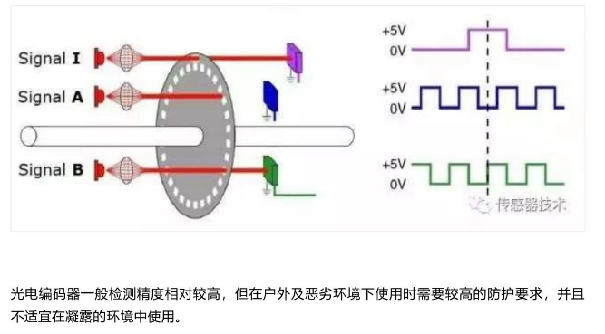
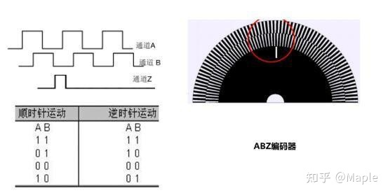
编码器一般指AB相正交脉冲的增量器件,有的还会有一个Z相信号,用来指示零位;
霍尔传感器一般是指ABC三个成120度角度间隔排列的器件,这种传感器一般集成在电机内部,电机每转一圈会生成6N个信号,每个信号代表电机转到了特定的角度;
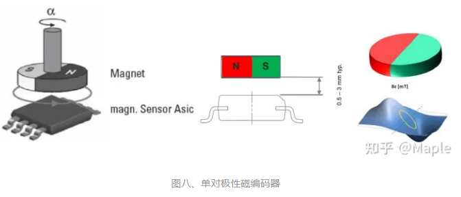
磁编码器本质上也是靠霍尔效应检测,但它是一种输出绝对位置的器件,这类传感器一般都有多种接口,如SPI、IIC、模拟值或PWM占空比。
编码器
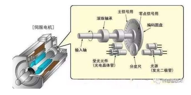
编码器是一种用于运动控制的传感器,利用光电、电磁、电容或者电感等感应原理,来检测物体的机械或者位置变化,然后把信息转化为电信号输出,作为运动的反馈。
旋转编码器
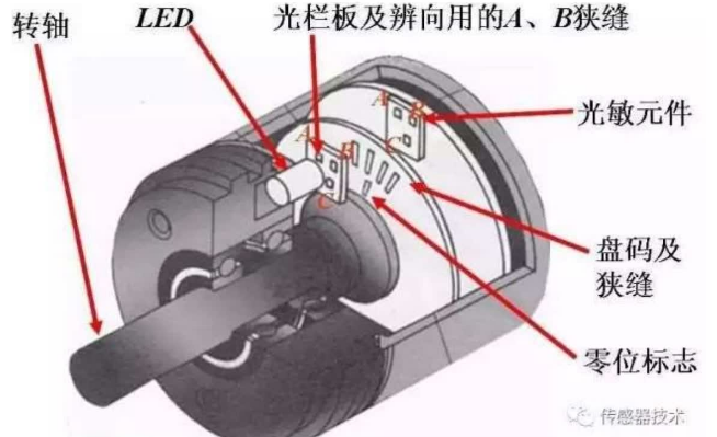
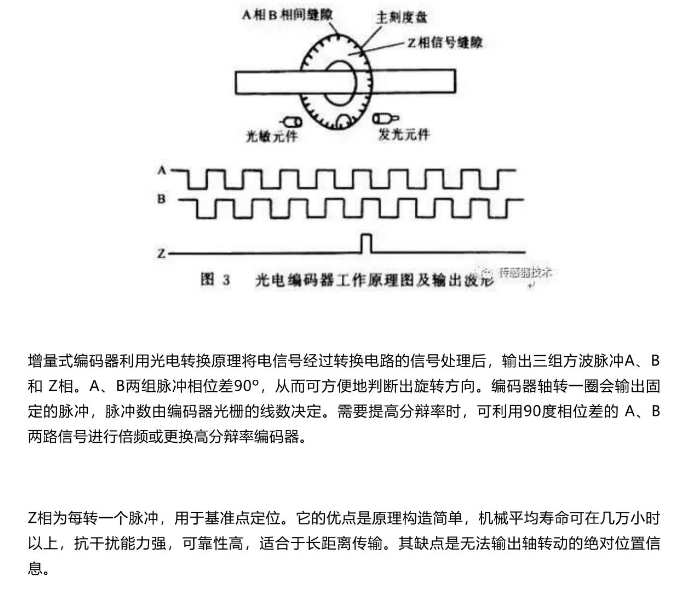
光电编码器
通过光电转换,将输出轴的角位移、角速度等机械两转化为电脉冲,以数字量输出。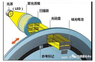

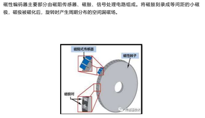
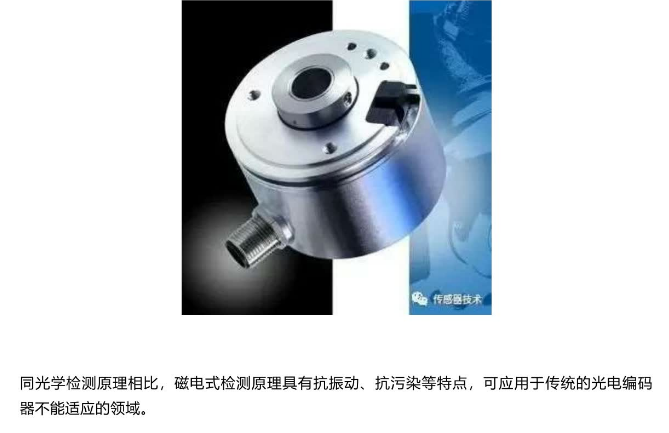
磁式编码器

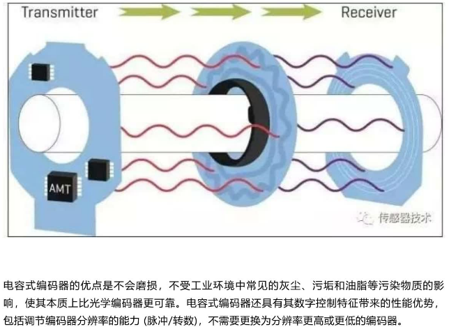
电容式编码器

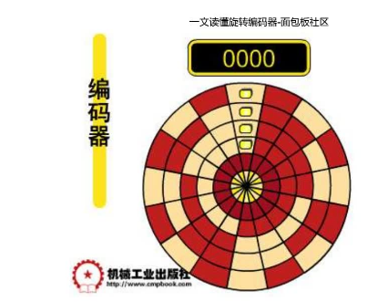
增量式编码器


资料
链接:https://pan.baidu.com/s/1Hp1fucofpC7nCn8-D8w_0A?pwd=pvpm
提取码:pvpm
代码
SimpleFOC Library设计了两种正交编码器的计数方法:
正交计数:对信号A和B的每次跳变都进行采样,这样在每个脉冲周期内将有四次信号跳变,采样四次,计数四次(即CPR Count Per Rotation),具体计算见以下源码。 普通计数:对信号A和B的上升沿进行计数,这样每个脉冲周期内将有两次信号跳变,采样两次,但只对某一个通道计数一次(即PPR Pulses Per Rotation),具体计算见以下源码。 正交模式下CPR = PPR*4 普通模式下CPR = PPR,显然正交模式下分辨率更高,但系统开支也更大,如果对分辨率要求不高可以使用普通模式。
MCU对A和B信号线连接的两个IO口使能外部中断,中断回调函数中实现了计数,回调函数源码如下所示,A和B两个通道的回调函数内容一样,只以A通道为例说明。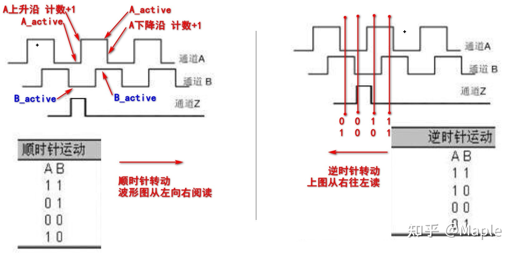
//定义对象,使能外部中断Encoder encoder = Encoder(2, 3, 8192); //定义正交编码器对象,连接到2和3号引脚,编码器PPR=8192void doA(){encoder.handleA();} //A通道中断回调函数void doB(){encoder.handleB();} //B通道中断回调函数encoder.enableInterrupts(doA, doB); //使能外部中断,设置回调函数void Encoder::enableInterrupts(void (*doA)(), void(*doB)(), void(*doIndex)()){// attach interrupt if functions providedswitch(quadrature){ //quadrature:是否开启正交模式case Quadrature::ON:// A callback and B callbackif(doA != nullptr) attachInterrupt(digitalPinToInterrupt(pinA), doA, CHANGE);if(doB != nullptr) attachInterrupt(digitalPinToInterrupt(pinB), doB, CHANGE);break;case Quadrature::OFF:// A callback and B callbackif(doA != nullptr) attachInterrupt(digitalPinToInterrupt(pinA), doA, RISING);if(doB != nullptr) attachInterrupt(digitalPinToInterrupt(pinB), doB, RISING);break;}//如果有Z相信号线,使能Z相的中断if(hasIndex() && doIndex != nullptr) attachInterrupt(digitalPinToInterrupt(index_pin), doIndex, CHANGE);}// Encoder interrupt callback functions// A channelvoid Encoder::handleA(){bool A = digitalRead(pinA); //测量A引脚高低电平switch (quadrature){case Quadrature::ON: //正交模式下:// CPR = 4xPPRif ( A != A_active ) //如果A引脚状态不等于"当前记录的状态"{//如果A引脚"当前记录的状态"等于B引脚"当前记录的状态"计数+1//对应图六中左侧A信号的上升沿与下降沿状态//否则为逆时针旋转,计数-1pulse_counter += (A_active == B_active) ? 1 : -1;pulse_timestamp = _micros();A_active = A; //更新A引脚当前状态}break;case Quadrature::OFF: //普通模式下// CPR = PPRif(A && !digitalRead(pinB)) //如果A引脚是高电平且B引脚是低电平{pulse_counter++; //计数+1,对应图六中左上角A上升沿状态pulse_timestamp = _micros();}break;}}
霍尔传感器
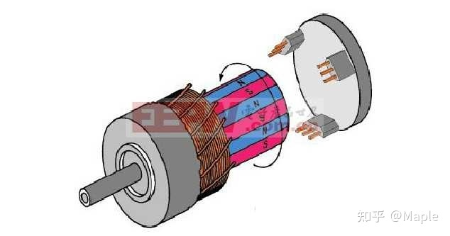
如上图所示,右侧的3个器件就是霍尔传感器,它们成120度夹角安装,也有60度安装的,但控制逻辑不一样。本节以一对极120度夹角电机模型说明。一对极指转子只有一对磁铁NS极,图四为多对极电机。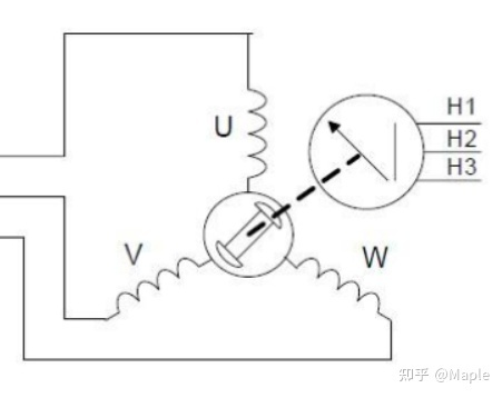
按特定的组合给电机的UVW三相供电,如U+,V-,W断开,此时电机转子将转到某一固定位置,假设为扇区Sector1,然后切换供电状态为W+,V-,U断开,电机将继续旋转60度到扇区二,按特定的顺序依次切换供电状态,电机将会一直转动下去,共有6种供电状态,对应着6个扇区,6种霍尔传感器的触发状态,如下图所示。
图六、霍尔的六种触发状态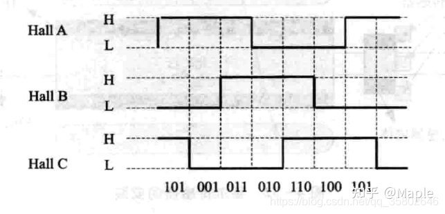
霍尔传感器就是根据这六种状态确定转子的位置,加上这6种状态的循环次数就是当前电机转子的真实位置。
//HallSensor.h//霍尔传感器状态与扇区对应关系// seq 1 > 5 > 4 > 6 > 2 > 3 > 1 000 001 010 011 100 101 110 111const int8_t ELECTRIC_SECTORS[8] = { -1, 0, 4, 5, 2, 1, 3 , -1 };
霍尔位置传感器的程序源码与ABZ正交编码器程序源码基本相同,引脚配置和外部中断设置基本相同,主要内容在updateState函数中,下边简单分析updateState函数。
void HallSensor::updateState(){long new_pulse_timestamp = _micros();//刷新三个霍尔传感器的状态int8_t new_hall_state = C_active + (B_active << 1) + (A_active << 2);//去除噪声// glitch avoidance #1 - sometimes we get an interrupt but pins haven't changedif (new_hall_state == hall_state) {return;}hall_state = new_hall_state;//匹配当前所在扇区int8_t new_electric_sector = ELECTRIC_SECTORS[hall_state];static Direction old_direction;//if (new_electric_sector - electric_sector > 3) { //如从扇区0转到了扇区5,则循环次数-1//underflowdirection = Direction::CCW;electric_rotations += direction;} else if (new_electric_sector - electric_sector < (-3)) {//如从扇区5转到了扇区0,则循环次数+1//overflowdirection = Direction::CW;electric_rotations += direction;} else {direction = (new_electric_sector > electric_sector)? Direction::CW : Direction::CCW;}electric_sector = new_electric_sector;// glitch avoidance #2 changes in direction can cause velocity spikes. Possible improvements needed in this areaif (direction == old_direction) {// not oscilating or just changed directionpulse_diff = new_pulse_timestamp - pulse_timestamp;} else {pulse_diff = 0;}pulse_timestamp = new_pulse_timestamp;total_interrupts++;old_direction = direction;if (onSectorChange != nullptr) onSectorChange(electric_sector);}
磁编码器
磁编码器有基于霍尔效应原理的,也有基于磁阻效应的。SimpleFOC项目使用的有以下几种,这里以AS5600说明。
/** Typical configuration for the 12bit AMS AS5600 magnetic sensor over I2C interface */MagneticSensorI2CConfig_s AS5600_I2C = {.chip_address = 0x36,.bit_resolution = 12,.angle_register = 0x0C,.data_start_bit = 11};/** Typical configuration for the 12bit AMS AS5048 magnetic sensor over I2C interface */MagneticSensorI2CConfig_s AS5048_I2C = {.chip_address = 0x40, // highly configurable. if A1 and A2 are held low, this is probable value.bit_resolution = 14,.angle_register = 0xFE,.data_start_bit = 15};/** Typical configuration for the 14bit AMS AS5147 magnetic sensor over SPI interface */MagneticSensorSPIConfig_s AS5147_SPI = {.spi_mode = SPI_MODE1,.clock_speed = 1000000,.bit_resolution = 14,.angle_register = 0x3FFF,.data_start_bit = 13,.command_rw_bit = 14,.command_parity_bit = 15};// AS5048 and AS5047 are the same as AS5147MagneticSensorSPIConfig_s AS5048_SPI = AS5147_SPI;MagneticSensorSPIConfig_s AS5047_SPI = AS5147_SPI;/** Typical configuration for the 14bit MonolithicPower MA730 magnetic sensor over SPI interface */MagneticSensorSPIConfig_s MA730_SPI = {.spi_mode = SPI_MODE0,.clock_speed = 1000000,.bit_resolution = 14,.angle_register = 0x0000,.data_start_bit = 15,.command_rw_bit = 0, // not required.command_parity_bit = 0 // parity not implemented};
原理
AS5600
是基于霍尔的旋转磁位置传感器,有12位高分辨率,使用平面传感器来将垂直于芯片表面的磁场分量转换为电压。它有3种输出方式,模拟值,PWM和IIC。
模拟值模式
//examples\utils\sensor_test\magnetic_sensors\magnetic_sensor_analog_example\find_raw_min_max\find_raw_min_max.ino#include <SimpleFOC.h>/*** 编码器处于Analog模式,指定AD引脚,它的电压与位置成线性正比*///AD使用A1引脚,AD最小值为14,最大值为1020,10位AD采样MagneticSensorAnalog sensor = MagneticSensorAnalog(A1, 14, 1020);void setup(){// monitoring portSerial.begin(115200);//传感器初始化,读取一次AD值,并记录当前时间sensor.init();Serial.println("Sensor ready");_delay(1000);}void loop() {// display the angle and the angular velocity to the terminalSerial.print(sensor.getAngle());Serial.print("\t");Serial.println(sensor.getVelocity());}
//src\sensors\MagneticSensorAnalog.cpp#include "MagneticSensorAnalog.h"MagneticSensorAnalog::MagneticSensorAnalog(uint8_t _pinAnalog, int _min_raw_count, int _max_raw_count){pinAnalog = _pinAnalog; //AD引脚cpr = _max_raw_count - _min_raw_count; //cpr计算min_raw_count = _min_raw_count;max_raw_count = _max_raw_count;if(pullup == Pullup::USE_INTERN){pinMode(pinAnalog, INPUT_PULLUP);}else{pinMode(pinAnalog, INPUT);}}void MagneticSensorAnalog::init(){// velocity calculation initangle_prev = 0;velocity_calc_timestamp = _micros();// full rotations tracking numberfull_rotation_offset = 0;raw_count_prev = getRawCount(); //读取一次当前AD值}// Shaft angle calculation// angle is in radians [rad]float MagneticSensorAnalog::getAngle(){//读取一次当前AD值raw_count = getRawCount();//计算AD值变化量,如果变化量大于0.8cpr,则认为已经进入下一圈了,或者是后退到上一圈了int delta = raw_count - raw_count_prev;// if overflow happened track it as full rotationif(abs(delta) > (0.8*cpr) ) full_rotation_offset += delta > 0 ? -_2PI : _2PI;//计算绝对角度,弧度float angle = full_rotation_offset + ( (float) (raw_count) / (float)cpr) * _2PI;//计算速度long now = _micros();float Ts = ( now - velocity_calc_timestamp)*1e-6;// quick fix for strange cases (micros overflow)if(Ts <= 0 || Ts > 0.5) Ts = 1e-3;velocity = (angle - angle_prev)/Ts;// save variables for future passraw_count_prev = raw_count;angle_prev = angle;velocity_calc_timestamp = now;return angle;}// function reading the raw counter of the magnetic sensorint MagneticSensorAnalog::getRawCount(){return analogRead(pinAnalog);//AD阻塞采样}
磁编码器的模拟值输出方式计算位置原理十分简单,只是一个AD值到角度的线性转换,需要注意的是AD的最大最小值最好自己测量一下,避免误差。另外一个需要注意的地方是getAngle()函数需要以较高的频率调用(频率跟电机转动速度相关),否则可能会导致角度计算错误,最好是使用定时器定时调用,或者在多任务系统种单独一个任务以固定周期调用该函数。
上述源码AD采样使用的是阻塞方式采样,STM32中我们可以使用中断或DMA中断方式采样,在中断函数中调用getAngle()函数,并开启下一次采样。
PWM模式
PWM模式和模拟值输出模式很相似,只是将模拟值输出的电压变成了PWM形式,PWM的高电平时间与角度成正比。
examples\utils\sensor_test\magnetic_sensors\magnetic_sensor_pwm_example\magnetic_sensor_pwm\magnetic_sensor_pwm.ino#include <SimpleFOC.h>/*** MagneticSensorPWM(uint8_t MagneticSensorPWM, int _min, int _max)* - pinPWM - PWM输入引脚* - min_raw_count - 最短高电平时间us* - max_raw_count - 最长高电平时间us*/MagneticSensorPWM sensor = MagneticSensorPWM(2, 4, 904);//定义中断回调函数void doPWM(){sensor.handlePWM();}void setup() {// monitoring portSerial.begin(115200);// initialise magnetic sensor hardwaresensor.init();//使能外部中断(监测引脚上升沿下降沿)检测PWM引脚高电平时间//如果注释掉这一句,则以默认的阻塞方式检测PWM引脚高电平时间sensor.enableInterrupt(doPWM);Serial.println("Sensor ready");_delay(1000);}void loop() {// display the angle and the angular velocity to the terminalSerial.print(sensor.getAngle());Serial.print("\t");Serial.println(sensor.getVelocity());}
IIC模式
AS5600可以使用IIC通信方式得到角度数据,需要注意的是,AS5600的地址是固定的,也就是说IIC总线上只能有一个AS5600。如果想要使用多个AS5600就需要多个IIC总线。
//examples\utils\sensor_test\magnetic_sensors\magnetic_sensor_i2c_example\magnetic_sensor_i2c_example.ino#include <SimpleFOC.h>// Example of AS5600 configurationMagneticSensorI2C sensor = MagneticSensorI2C(AS5600_I2C);void setup() {// monitoring portSerial.begin(115200);//i2C使用快速模式400KWire.setClock(400000);// initialise magnetic sensor hardwaresensor.init();Serial.println("Sensor ready");_delay(1000);}void loop() {// display the angle and the angular velocity to the terminalSerial.print(sensor.getAngle());Serial.print("\t");Serial.println(sensor.getVelocity());}
参考

若有收获,就点个赞吧
0 人点赞
