:::info 【总结】
- 序列监测器的编码问题;
- 状态图的绘制;
- 三段式状态机的编写。
:::
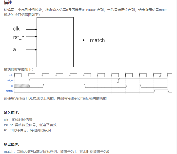
根据模块的时序图可以发现,输入信号a的序列是01110001,当检测到这个序列以后,match信号并没有在下一个clk的上升沿立即拉高,而是等了一拍以后再拉高。
:::info 使用三段式状态机写序列监测器:
- 状态编码问题:与之前状态机的编码方式不同,之前的两篇在实现状态机的时候采用的都是连续编码的形式;而这里采用了独热码的形式(有且只有1bit为1);
- 明确状态机存在几个状态:这里一共有8bit,算上IDLE状态就一共有9个状态;
- 明确IDLE状态如何确定的:IDLE状态一般是检测到的第一个bit的相反状态,这里监测到的第一个bit是0,与之相反,IDLE状态就是1.
:::
``verilogtimescale 1ns/1ns
module sequence_detect( input clk, input rst_n, input a, output reg match );
reg [7:0] cs; reg [7:0] ns;
parameter idle = 4’b0000; parameter s0 = 4’b0001; parameter s1 = 4’b0010; parameter s2 = 4’b0011; parameter s3 = 4’b0100; parameter s4 = 4’b0101; parameter s5 = 4’b0110; parameter s6 = 4’b0111; parameter s7 = 4’b1000;
always @(posedge clk or negedge rst_n) begin if(!rst_n) begin cs <= 8’b0000_0000; end else begin cs <= ns; end end
always @(*) begin case(cs) idle : ns = (a == 1’b1)? idle : s0; s0 : ns = (a == 1’b1)? s1 : s0; s1 : ns = (a == 1’b1)? s2 : s0; s2 : ns = (a == 1’b1)? s3 : s0; s3 : ns = (a == 1’b1)? s0 : s4; s4 : ns = (a == 1’b1)? s1 : s5; s5 : ns = (a == 1’b1)? s1 : s6; s6 : ns = (a == 1’b1)? s7 : s0; s7 : ns = (a == 1’b1)? s2 : s0; default : ns = idle; endcase end
wire match_tmp; assign match_tmp = (cs == s7);
always @(posedge clk or negedge rst_n) begin if(!rst_n) begin match <= 1’b0; end else begin match <= match_tmp; end end
endmodule
```

若有收获,就点个赞吧
0 人点赞
