学习目标
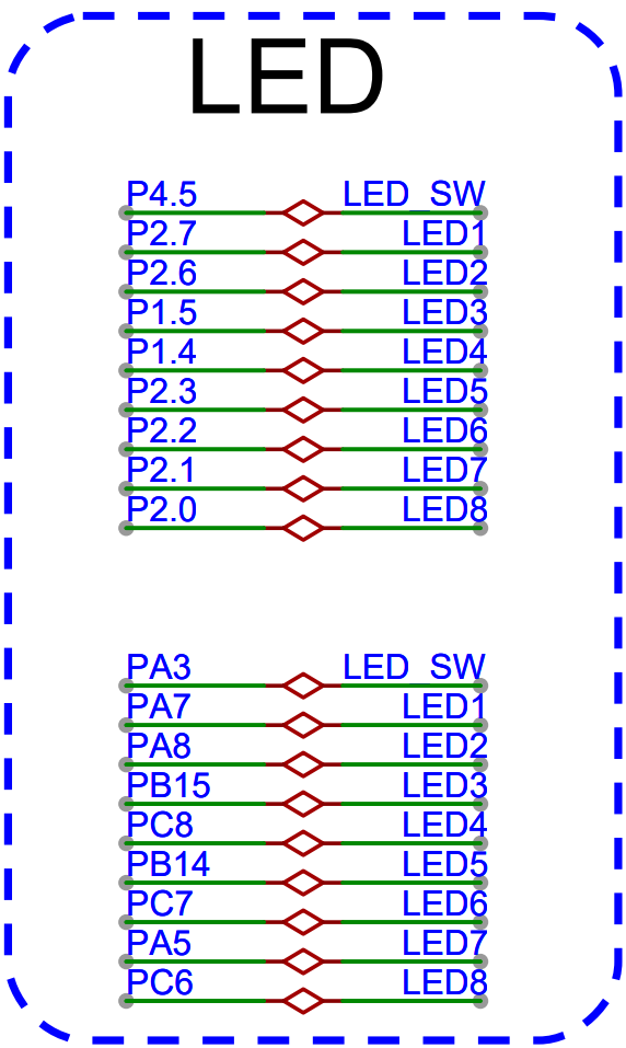
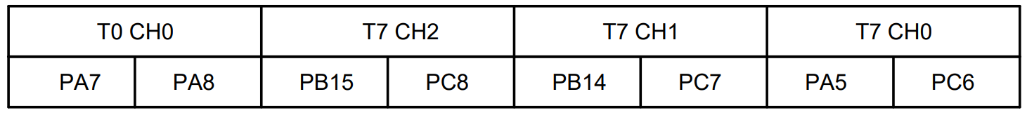
| 定时器 | 通道 | 引脚 | AF | 极性 | LED序号 |
|---|---|---|---|---|---|
| T0 | ch0 | PA7 | AF1 | ON | LED1 |
| PA8 | AF1 | OP | LED2 | ||
| T7 | ch2 | PB15 | AF3 | ON | LED3 |
| PC8 | AF3 | OP | LED4 | ||
| ch1 | PB14 | AF3 | ON | LED5 | |
| PC7 | AF3 | OP | LED6 | ||
| ch0 | PA5 | AF3 | ON | LED7 | |
| PC6 | AF3 | OP | LED8 |
高级定时器单通道互补功能
开发流程
- 添加Timer依赖
- 初始化PWM
- 配置通道的P极和N极
- PWM占空比控制
通道配置
////////// 配置输出通道timer_oc_parameter_struct tops;// ch0timer_channel_output_struct_para_init(&tops);// n configtops.outputnstate = TIMER_CCXN_ENABLE;// p configtops.outputstate = TIMER_CCX_ENABLE;timer_channel_output_config(timerx, TIMER_CH_0, &tops);
- ocnpolarity:N极性电平
- ocpolarity:P极性电平
完整代码
```cinclude “gd32f4xx.h”
include “systick.h”
include
include “main.h”
include “Usart0.h”
// T0 // ch0 PA7 ON // ch0 PA8 OP
// 分频计数 // 周期计数
define PRESCALER (10 - 1)
define PERIOD (SystemCoreClock / 100000 - 1)
void Usart0_recv(uint8_t *data, uint32_t len) {
}
static void PWM_config() { uint32_t timerx = TIMER0; uint32_t timerx_rcu = RCU_TIMER0; uint32_t timerx_psc = RCU_TIMER_PSC_MUL2;
uint32_t timerx_prescaler = PRESCALER; // 分频计数uint32_t timerx_period = PERIOD; // 周期计数uint32_t timerx_ch0_p_port = GPIOA;uint32_t timerx_ch0_p_port_rcu = RCU_GPIOA;uint32_t timerx_ch0_p_pin = GPIO_PIN_8;uint32_t timerx_ch0_p_af = GPIO_AF_1;uint32_t timerx_ch0_n_port = GPIOA;uint32_t timerx_ch0_n_port_rcu = RCU_GPIOA;uint32_t timerx_ch0_n_pin = GPIO_PIN_7;uint32_t timerx_ch0_n_af = GPIO_AF_1;/*************** GPIO config **************///// ch0 p// 配置时钟rcu_periph_clock_enable(timerx_ch0_p_port_rcu);// 配置GPIO模式gpio_mode_set(timerx_ch0_p_port, GPIO_MODE_AF, GPIO_PUPD_NONE, timerx_ch0_p_pin);// 配置GPIO输出gpio_output_options_set(timerx_ch0_p_port, GPIO_OTYPE_PP, GPIO_OSPEED_MAX, timerx_ch0_p_pin);// 配置复用功能gpio_af_set(timerx_ch0_p_port, timerx_ch0_p_af, timerx_ch0_p_pin);//// ch0 n// 配置时钟rcu_periph_clock_enable(timerx_ch0_n_port_rcu);// 配置GPIO模式gpio_mode_set(timerx_ch0_n_port, GPIO_MODE_AF, GPIO_PUPD_NONE, timerx_ch0_n_pin);// 配置GPIO输出gpio_output_options_set(timerx_ch0_n_port, GPIO_OTYPE_PP, GPIO_OSPEED_MAX, timerx_ch0_n_pin);// 配置复用功能gpio_af_set(timerx_ch0_n_port, timerx_ch0_n_af, timerx_ch0_n_pin);/*************** Timer config *************/// 时钟配置rcu_periph_clock_enable(timerx_rcu);// 复位定时器timer_deinit(timerx);// 倍频配置rcu_timer_clock_prescaler_config(timerx_psc);// 初始化定时器timer_parameter_struct tps;timer_struct_para_init(&tps);tps.prescaler = timerx_prescaler; // 分频计数tps.period = timerx_period; // 周期计数timer_init(timerx, &tps);////////// 配置输出通道timer_oc_parameter_struct tops;// ch0timer_channel_output_struct_para_init(&tops);// n configtops.outputnstate = TIMER_CCXN_ENABLE;// p configtops.outputstate = TIMER_CCX_ENABLE;timer_channel_output_config(timerx, TIMER_CH_0, &tops);////////// 输出模式配置// ch0timer_channel_output_mode_config(timerx, TIMER_CH_0, TIMER_OC_MODE_PWM0);////////// Break配置timer_break_parameter_struct tbps;timer_break_struct_para_init(&tbps);tbps.breakpolarity = TIMER_BREAK_POLARITY_HIGH;tbps.outputautostate = TIMER_OUTAUTO_ENABLE;tbps.breakstate = TIMER_BREAK_ENABLE;timer_break_config(timerx, &tbps);// 初始化timer_enable(timerx);
}
static void PWM_update_ch0(float duty) { uint32_t timerx = TIMER0; uint32_t timerx_chn = TIMER_CH_0;
uint32_t pulse = duty * (PERIOD + 1) / 100;/***************** pwm update *******************/// 配置输出的占空比timer_channel_output_pulse_value_config(timerx, timerx_chn, pulse);
}
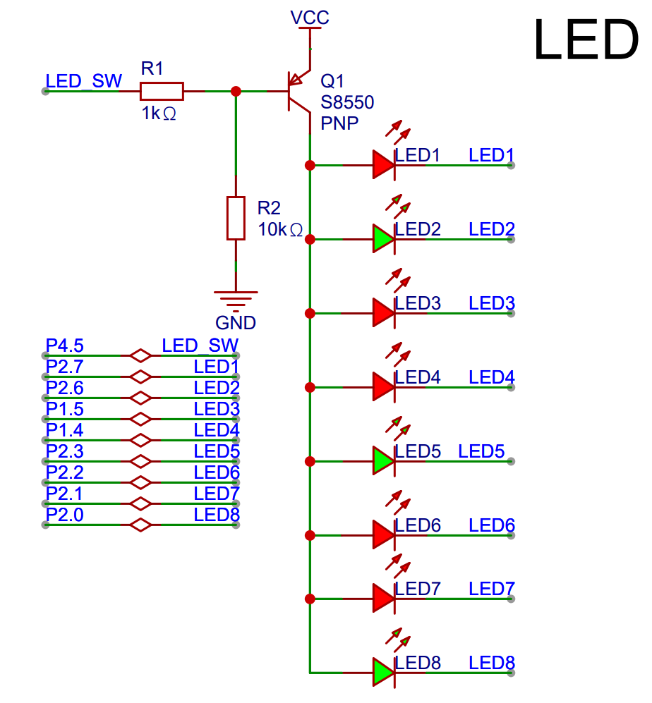
static void GPIO_config() { // 配置时钟 rcu_periph_clock_enable(RCU_GPIOA); // 配置GPIO模式 gpio_mode_set(GPIOA, GPIO_MODE_OUTPUT, GPIO_PUPD_NONE, GPIO_PIN_3); // 配置GPIO输出 gpio_output_options_set(GPIOA, GPIO_OTYPE_PP, GPIO_OSPEED_MAX, GPIO_PIN_3); }
int main(void) { systick_config(); nvic_priority_group_set(NVIC_PRIGROUP_PRE2_SUB2); Usart0_init(); GPIO_config(); PWM_config();
gpio_bit_reset(GPIOA, GPIO_PIN_3);int8_t i;while(1) {for(i = 0; i < 25; i++) {PWM_update_ch0(i);delay_1ms(50);}for(i = 24; i >= 0; i--) {PWM_update_ch0(i);delay_1ms(50);}delay_1ms(1000);}
}
<a name="q1l0U"></a>### 高级定时器多通道互补功能<a name="qXpuR"></a>#### 开发流程1. 添加Timer依赖2. 初始化PWM3. 配置通道的P极和N极4. PWM占空比控制<a name="sLxj0"></a>#### 多通道配置```ctimer_oc_parameter_struct tops;timer_channel_output_struct_para_init(&tops);// n configtops.outputnstate = TIMER_CCXN_ENABLE;tops.ocnpolarity = TIMER_OCN_POLARITY_LOW;// p configtops.outputstate = TIMER_CCX_ENABLE;tops.ocpolarity = TIMER_OC_POLARITY_LOW;///// ch0timer_channel_output_config(timerx, TIMER_CH_0, &tops);///// ch1timer_channel_output_config(timerx, TIMER_CH_1, &tops);///// ch2timer_channel_output_config(timerx, TIMER_CH_2, &tops);
完整代码
#include "gd32f4xx.h"#include "systick.h"#include <stdio.h>#include "main.h"#include "Usart0.h"// T7// ch0// N: PA5 ON// P: PC6 OP// ch1// N: PB14 ON// P: PC7 OP// ch2// N: PB15 ON// P: PC8 OP// 分频计数// 周期计数#define PRESCALER (10 - 1)#define PERIOD (SystemCoreClock / 100000 - 1)void Usart0_recv(uint8_t *data, uint32_t len) {}static void PWM_config() {uint32_t timerx = TIMER7;uint32_t timerx_rcu = RCU_TIMER7;uint32_t timerx_psc = RCU_TIMER_PSC_MUL2;uint32_t timerx_prescaler = PRESCALER; // 分频计数uint32_t timerx_period = PERIOD; // 周期计数// ch0uint32_t timerx_ch0_n_port = GPIOA;uint32_t timerx_ch0_n_port_rcu = RCU_GPIOA;uint32_t timerx_ch0_n_pin = GPIO_PIN_5;uint32_t timerx_ch0_n_af = GPIO_AF_3;uint32_t timerx_ch0_p_port = GPIOC;uint32_t timerx_ch0_p_port_rcu = RCU_GPIOC;uint32_t timerx_ch0_p_pin = GPIO_PIN_6;uint32_t timerx_ch0_p_af = GPIO_AF_3;// ch1uint32_t timerx_ch1_n_port = GPIOB;uint32_t timerx_ch1_n_port_rcu = RCU_GPIOB;uint32_t timerx_ch1_n_pin = GPIO_PIN_14;uint32_t timerx_ch1_n_af = GPIO_AF_3;uint32_t timerx_ch1_p_port = GPIOC;uint32_t timerx_ch1_p_port_rcu = RCU_GPIOC;uint32_t timerx_ch1_p_pin = GPIO_PIN_7;uint32_t timerx_ch1_p_af = GPIO_AF_3;// ch2uint32_t timerx_ch2_n_port = GPIOB;uint32_t timerx_ch2_n_port_rcu = RCU_GPIOB;uint32_t timerx_ch2_n_pin = GPIO_PIN_15;uint32_t timerx_ch2_n_af = GPIO_AF_3;uint32_t timerx_ch2_p_port = GPIOC;uint32_t timerx_ch2_p_port_rcu = RCU_GPIOC;uint32_t timerx_ch2_p_pin = GPIO_PIN_8;uint32_t timerx_ch2_p_af = GPIO_AF_3;/*************** GPIO config **************///// ch0//// p// 配置时钟rcu_periph_clock_enable(timerx_ch0_p_port_rcu);// 配置GPIO模式gpio_mode_set(timerx_ch0_p_port, GPIO_MODE_AF, GPIO_PUPD_NONE, timerx_ch0_p_pin);// 配置GPIO输出gpio_output_options_set(timerx_ch0_p_port, GPIO_OTYPE_PP, GPIO_OSPEED_MAX, timerx_ch0_p_pin);// 配置复用功能gpio_af_set(timerx_ch0_p_port, timerx_ch0_p_af, timerx_ch0_p_pin);//// n// 配置时钟rcu_periph_clock_enable(timerx_ch0_n_port_rcu);// 配置GPIO模式gpio_mode_set(timerx_ch0_n_port, GPIO_MODE_AF, GPIO_PUPD_NONE, timerx_ch0_n_pin);// 配置GPIO输出gpio_output_options_set(timerx_ch0_n_port, GPIO_OTYPE_PP, GPIO_OSPEED_MAX, timerx_ch0_n_pin);// 配置复用功能gpio_af_set(timerx_ch0_n_port, timerx_ch0_n_af, timerx_ch0_n_pin);//// ch1//// p// 配置时钟rcu_periph_clock_enable(timerx_ch1_p_port_rcu);// 配置GPIO模式gpio_mode_set(timerx_ch1_p_port, GPIO_MODE_AF, GPIO_PUPD_NONE, timerx_ch1_p_pin);// 配置GPIO输出gpio_output_options_set(timerx_ch1_p_port, GPIO_OTYPE_PP, GPIO_OSPEED_MAX, timerx_ch1_p_pin);// 配置复用功能gpio_af_set(timerx_ch1_p_port, timerx_ch1_p_af, timerx_ch1_p_pin);//// n// 配置时钟rcu_periph_clock_enable(timerx_ch1_n_port_rcu);// 配置GPIO模式gpio_mode_set(timerx_ch1_n_port, GPIO_MODE_AF, GPIO_PUPD_NONE, timerx_ch1_n_pin);// 配置GPIO输出gpio_output_options_set(timerx_ch1_n_port, GPIO_OTYPE_PP, GPIO_OSPEED_MAX, timerx_ch1_n_pin);// 配置复用功能gpio_af_set(timerx_ch1_n_port, timerx_ch1_n_af, timerx_ch1_n_pin);//// ch2//// p// 配置时钟rcu_periph_clock_enable(timerx_ch2_p_port_rcu);// 配置GPIO模式gpio_mode_set(timerx_ch2_p_port, GPIO_MODE_AF, GPIO_PUPD_NONE, timerx_ch2_p_pin);// 配置GPIO输出gpio_output_options_set(timerx_ch2_p_port, GPIO_OTYPE_PP, GPIO_OSPEED_MAX, timerx_ch2_p_pin);// 配置复用功能gpio_af_set(timerx_ch2_p_port, timerx_ch2_p_af, timerx_ch2_p_pin);//// n// 配置时钟rcu_periph_clock_enable(timerx_ch2_n_port_rcu);// 配置GPIO模式gpio_mode_set(timerx_ch2_n_port, GPIO_MODE_AF, GPIO_PUPD_NONE, timerx_ch2_n_pin);// 配置GPIO输出gpio_output_options_set(timerx_ch2_n_port, GPIO_OTYPE_PP, GPIO_OSPEED_MAX, timerx_ch2_n_pin);// 配置复用功能gpio_af_set(timerx_ch2_n_port, timerx_ch2_n_af, timerx_ch2_n_pin);/*************** Timer config *************/// 时钟配置rcu_periph_clock_enable(timerx_rcu);// 复位定时器timer_deinit(timerx);// 倍频配置rcu_timer_clock_prescaler_config(timerx_psc);// 初始化定时器timer_parameter_struct tps;timer_struct_para_init(&tps);tps.prescaler = timerx_prescaler; // 分频计数tps.period = timerx_period; // 周期计数timer_init(timerx, &tps);////////// 配置输出通道timer_oc_parameter_struct tops;///// ch0timer_channel_output_struct_para_init(&tops);// n configtops.outputnstate = TIMER_CCXN_ENABLE;tops.ocpolarity = TIMER_OC_POLARITY_LOW;// p configtops.outputstate = TIMER_CCX_ENABLE;tops.ocpolarity = TIMER_OC_POLARITY_LOW;timer_channel_output_config(timerx, TIMER_CH_0, &tops);///// ch1timer_channel_output_struct_para_init(&tops);// n configtops.outputnstate = TIMER_CCXN_ENABLE;// p configtops.outputstate = TIMER_CCX_ENABLE;tops.ocpolarity = TIMER_OC_POLARITY_LOW;timer_channel_output_config(timerx, TIMER_CH_1, &tops);///// ch2timer_channel_output_struct_para_init(&tops);// n configtops.outputnstate = TIMER_CCXN_ENABLE;// p configtops.outputstate = TIMER_CCX_ENABLE;tops.ocpolarity = TIMER_OC_POLARITY_LOW;timer_channel_output_config(timerx, TIMER_CH_2, &tops);////////// 输出模式配置// ch0timer_channel_output_mode_config(timerx, TIMER_CH_0, TIMER_OC_MODE_PWM0);// ch1timer_channel_output_mode_config(timerx, TIMER_CH_1, TIMER_OC_MODE_PWM0);// ch2timer_channel_output_mode_config(timerx, TIMER_CH_2, TIMER_OC_MODE_PWM0);////////// Break配置timer_break_parameter_struct tbps;timer_break_struct_para_init(&tbps);tbps.breakpolarity = TIMER_BREAK_POLARITY_HIGH;tbps.outputautostate = TIMER_OUTAUTO_ENABLE;tbps.breakstate = TIMER_BREAK_ENABLE;timer_break_config(timerx, &tbps);// 初始化timer_enable(timerx);}static void PWM_update_ch0(float duty) {uint32_t timerx = TIMER7;uint32_t timerx_chn = TIMER_CH_0;uint32_t pulse = duty * (PERIOD + 1) / 100;/***************** pwm update *******************/// 配置输出的占空比timer_channel_output_pulse_value_config(timerx, timerx_chn, pulse);}static void PWM_update_ch1(float duty) {uint32_t timerx = TIMER7;uint32_t timerx_chn = TIMER_CH_1;uint32_t pulse = duty * (PERIOD + 1) / 100;/***************** pwm update *******************/// 配置输出的占空比timer_channel_output_pulse_value_config(timerx, timerx_chn, pulse);}static void PWM_update_ch2(float duty) {uint32_t timerx = TIMER7;uint32_t timerx_chn = TIMER_CH_2;uint32_t pulse = duty * (PERIOD + 1) / 100;/***************** pwm update *******************/// 配置输出的占空比timer_channel_output_pulse_value_config(timerx, timerx_chn, pulse);}static void GPIO_config() {// 配置时钟rcu_periph_clock_enable(RCU_GPIOA);// 配置GPIO模式gpio_mode_set(GPIOA, GPIO_MODE_OUTPUT, GPIO_PUPD_NONE, GPIO_PIN_3);// 配置GPIO输出gpio_output_options_set(GPIOA, GPIO_OTYPE_PP, GPIO_OSPEED_MAX, GPIO_PIN_3);}int main(void){systick_config();nvic_priority_group_set(NVIC_PRIGROUP_PRE2_SUB2);Usart0_init();GPIO_config();PWM_config();gpio_bit_reset(GPIOA, GPIO_PIN_3);int8_t i;while(1) {for(i = 0; i < 25; i++) {PWM_update_ch0(i);PWM_update_ch1(i);PWM_update_ch2(i);delay_1ms(50);}for(i = 24; i >= 0; i--) {PWM_update_ch0(i);PWM_update_ch1(i);PWM_update_ch2(i);delay_1ms(50);}delay_1ms(1000);}}
练习题
- 实现互补pwm

若有收获,就点个赞吧
0 人点赞
