- 1. [ICON] DC motor [PORT] [ROTATE] rotates at power [POWER] %
- 2. [ICON] shutter [PORT] [SHUTTER_ACTION]
- 3. [ICON] servo [PORT] [SLOT] positioned at [DEGREE] angle
- 4. [ICON] fan [PORT] [FAN_ROTATE] rotates
- 5. [ICON]LED panel [PORT] shows image [FACE_PANEL] for [TIME] secs
- 6. [ICON]LED panel [PORT] shows image [FACE_PANEL]
- 7. [ICON] LED panel [PORT] shows image [FACE_PANEL] at x: [X] y: [Y]
- 8. [ICON] LED panel [PORT] shows text [TEXT]
- 9. [ICON]LED panel [PORT] shows text [TEXT] at x: [X] y: [Y]
- 10. [ICON] LED panel [PORT] shows number [NUMBER]
- 11. [ICON] LED panel [PORT] shows time [NUMBER1]:[NUMBER2]
- 12. [ICON] LED panel [PORT] clears screen
- 13. [ICON] RGB LED [PORT] lights up [LED_POSTION] with color [COLOR] for [TIME] secs
- 14. [ICON] RGB LED [PORT] lights up [LED_POSTION]with color [COLOR]
- 15. [ICON] RGB LED [PORT] lights up [LED_POSTION] with color red [R] green [G] blue [B]
- 16. [ICON]LED strip [PORT] [SLOT] all lights up with color [COLOR_LIST]
- 17. [ICON] LED strip [PORT] [SLOT] [POS] lights up with color [COLOR_LIST]
- 18. [ICON] LED strip [PORT] [SLOT] [POS] lights up with color red [R]green [G]blue [B]
- 19. [ICON] seven-segments [PORT] displays number [NUMBER]
- 20. [ICON] ultrasonic sensor [PORT] distance
- 21. [ICON]light sensor [PORT] light intensity
- 22. [ICON] sound sensor [PORT] volume
- 23. [ICON] line follower sensor [PORT] value
- 24. [ICON]line follower sensor [PORT] detects [LINEFOLLOW_STATE] being [BLACK_WHITE] ?
- 25. [ICON] temperature sensor [PORT] [SLOT]temeperature (℃)
- 26. [ICON] humiture sensor [PORT] [TEMP_HUMITURE]
- 27. [ICON] touch sensor [PORT] is touched?
- 28. [ICON] electronic compass [PORT] towards the north
- 29. [ICON] flame sensor [PORT]value
- 30. [ICON]gas sensor [PORT] value
- 31. [ICON]gyroscope [AXIS] angle
- 32. [ICON] PIR sensor [PORT] detects human’s motion?
- 33. [ICON]button [PORT] [FOUR_KEY] pressed?
- 34. [ICON]limit switch [PORT] [SLOT] pressed?
- 35. [ICON]potentiometer [PORT] value
- 36. [ICON]IR receiver [PORT]
- 37. [ICON] joystick [PORT] [AXIS_X_Y] value
1. [ICON] DC motor [PORT] [ROTATE] rotates at power [POWER] %

Makes the DC motor connected to the specified port of mBot run at the specified power in the specified direction
How to Use
mBot provides two ports that can be used to connect DC motors. Click to select the one to which the DC motor is connected.
DC motors can rotate clockwise or anticlockwise. Click to select the direction.
The power in this block refers to the percentage of the rated rotating speed of the motor. You can click the default power to define the one you want.
Setting range of the power: 0–100
Alternatively, you can put a reporter block of the numeric type into it, for example:
Example
Note: Ensure that you have connected a DC motor to motor port 1 of mBot.
When you press the space key, the DC motor starts to run clockwise at the power of 50%.
2. [ICON] shutter [PORT] [SHUTTER_ACTION]

Makes the shutter of the camera connected to the specified port of mBot enter the specified state
How to Use
Cameras can be connected to mBot through shutter modules (shown in the preceding figure). mBot provides four ports that can be used to connect shutter modules. Click to select the one to which the shutter module is connected.
This block provides four state options. Click to select the state you want.
Example
Note: Ensure that you have connected a camera to mBot through the shutter module at port 1.
When you press the space key, the shutter of the camera enters the pressed state.
3. [ICON] servo [PORT] [SLOT] positioned at [DEGREE] angle

Positions the servo horn on the servo connected at the specified slot of the RJ25 adapter connected to the specified port of mBot at the specified angle
How to Use
Servos can be connected to mBot through RJ25 adapters (shown in the preceding figure). mBot provides four ports that can be used to connect RJ25 adapters. Click to select the one to which the RJ25 adapter is connected.
The RJ25 adpater provides two slots for connecting servos. Click to select the one to which the servo is connected.
You can click the default angle to define the one you want.
Alternatively, you can put a reporter block of the numeric type into it, for example:
Example
Note: Ensure that you have connected a servo at slot 1 of the RJ25 connected to port 1 of mBot.
When you press the space key, the servo horn rotates and stops at the angle of 90 degrees.
4. [ICON] fan [PORT] [FAN_ROTATE] rotates

Makes the fan connected to the specified port of mBot run in the specified direction
How to Use
mBot provides four ports that can be used to connect fans. Click to select the one to which the fan is connected.
This block provides three direction options. Click to select the direction you want.
Example
Note: Ensure that you have connected a fan to mBot through port 1.
After you press the space key, the fan runs clockwise.
5. [ICON]LED panel [PORT] shows image [FACE_PANEL] for [TIME] secs

Displays the specified image on the display panel connected to the specified port of mBot for the specified period of time in seconds
How to Use
mBot provides four ports that can be used to connect display panels. Click to select the one to which the display panel is connected. Click the image and time to define the ones you want.
Alternatively, you can put a reporter block of the numeric type into it, for example:
Example
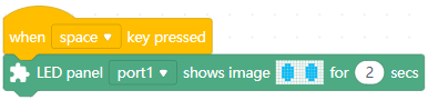
Note: Ensure that you have connected a display panel to mBot through port 1.
When you press the space key, the display panel displays the specified image for two seconds and then goes off.
6. [ICON]LED panel [PORT] shows image [FACE_PANEL]

Displays the specified image on the display panel connected to the specified port of mBot
How to Use
mBot provides four ports that can be used to connect display panels. Click to select the one to which the display panel is connected.
Click the image to define the one you want.
Example
Note: Ensure that you have connected a display panel to mBot through port 1.
When you press the space key, the display panel displays the specified image.
7. [ICON] LED panel [PORT] shows image [FACE_PANEL] at x: [X] y: [Y]

Displays the specified image in the specified position of the display panel connected to the specified port of mBot
How to Use
mBot provides four ports that can be used to connect display panels. Click to select the one to which the display panel is connected.
Click the image and coordinates to define the ones you want.
The display panel is a matrix panel of 8 (0–7) × 16 (0–15) points. The value of x indicates the number of horizontal offset points. A positive value indicate right offset, and a negative one indicates left offset. The value of y indicates the number of vertical offset points. A positive value indicates downward offset, and a negative one indicates upward offset.
For example, if the image is designed as follows:
when you use the block , setting the x and y values, the image is displayed in the following position on the display panel:
Setting range of x: –15 – +15
Setting range of y: –7 – +7
Alternatively, you can put reporter blocks of the numeric type into them, for example:
Example
Note: Ensure that you have connected a display panel to mBot through port 1.
When you press the space key, the display panel displays the specified image with a right offset of two points and an upward offset of one point (compared to the default position).
8. [ICON] LED panel [PORT] shows text [TEXT]

Displays the specified text on the display panel connected to the specified port of mBot
How to Use
mBot provides four ports that can be used to connect display panels. Click to select the one to which the display panel is connected.
Click the text to define the one you want.
Currently, this block supports only Latin characters, numbers, and symbols.
Alternatively, you can put a reporter block into it, for example:
Example
Note: Ensure that you have connected a display panel to mBot through port 1.
When you press the space key, the display panel displays hello.
9. [ICON]LED panel [PORT] shows text [TEXT] at x: [X] y: [Y]

Displays the specified text in the specified position of the display panel connected to the specified port of mBot
How to Use
mBot provides four ports that can be used to connect display panels. Click to select the one to which the display panel is connected.
Click the text to define the one you want.
Currently, this block supports only Latin characters, numbers, and symbols.
The display panel is a matrix panel of 8 (0–7) × 16 (0–15) points. The value of x indicates the number of horizontal offset points. A positive value indicate right offset, and a negative one indicates left offset. The value of y indicates the number of vertical offset points. A positive value indicates downward offset, and a negative one indicates upward offset.
Alternatively, you can put reporter blocks into them, for example:
Example
Note: Ensure that you have connected a display panel to mBot through port 1.
When you press the space key, the display panel displays hello with a right offset of two points and an upward offset of one point (compared to the default position).
10. [ICON] LED panel [PORT] shows number [NUMBER]

Displays the specified number on the display panel connected to the specified port of mBot
How to Use
mBot provides four ports that can be used to connect display panels. Click to select the one to which the display panel is connected.
Click the number to define the one you want.
Alternatively, you can put a reporter block of the numeric type into it, for example:
Example
Note: Ensure that you have connected a display panel to mBot through port 1.
When you press the space key, the display panel displays 2048.
11. [ICON] LED panel [PORT] shows time [NUMBER1]:[NUMBER2]

Displays the specified time on the display panel connected to the specified port of mBot
How to Use
mBot provides four ports that can be used to connect display panels. Click to select the one to which the display panel is connected.
Click the time to define the one you want.
The display range of the time is 00:00 to 23:59. When the hour or minute value you set exceeds the range, the hour value 23 or minute value 59 is displayed.
Alternatively, you can put reporter blocks of the numeric type into it, for example:
Example
Note: Ensure that you have connected a display panel to mBot through port 1.
When you press the space key, the display panel displays 12:00.
12. [ICON] LED panel [PORT] clears screen

Turns off the display panel connected to the specified port of mBot
How to Use
mBot provides four ports that can be used to connect display panels. Click to select the one to which the display panel is connected.
Example
Note: Ensure that you have connected a display panel to mBot through port 1.
When you press the space key, the display panel displays the specified image and goes off in two seconds.
13. [ICON] RGB LED [PORT] lights up [LED_POSTION] with color [COLOR] for [TIME] secs

Lights up the specified LED(s) of the RGB LED module connected to the specified port of mBot in the specified color for the specified period of time
How to Use
mBot provides four ports that can be used to connect display panels. Click to select the one to which the RGB LED module is connected.
An RGB LED module provides four LEDs. Click to select the one(s) you want.
Click to define the color through the settings of color, saturation, and brightness.
Click to set the period of time.
Alternatively, you can put a reporter block of the numeric type into it, for example:
Example
Note: Ensure that you have connected an RGB LED module to mBot through port 1.
When you press the space key, all the LEDs on the RGB LED module are lit up in red and go off in two seconds.
14. [ICON] RGB LED [PORT] lights up [LED_POSTION]with color [COLOR]

Lights up the specified LED(s) of the RGB LED module connected to the specified port of mBot in the specified color
How to Use
mBot provides four ports that can be used to connect display panels. Click to select the one to which the RGB LED module is connected.
An RGB LED module provides four LEDs. Click to select the one(s) you want.
Click to define the color through the settings of color, saturation, and brightness.
Example
Note: Ensure that you have connected an RGB LED module to mBot through port 1.
When you press the space key, all the LEDs on the RGB LED module are lit up in red.
15. [ICON] RGB LED [PORT] lights up [LED_POSTION] with color red [R] green [G] blue [B]

Lights up the specified LED(s) of the RGB LED module connected to the specified port of mBot in the color that is the combination of the specified intensity of red, green, and blue
How to Use
mBot provides four ports that can be used to connect display panels. Click to select the one to which the RGB LED module is connected.
An RGB LED module provides four LEDs. Click to select the one(s) you want.
Click to define the color by setting the intensity of red, green, and blue.
Intensity range of red, green, and blue: 0–255
Example
Note: Ensure that you have connected an RGB LED module to mBot through port 1.
When you press the space key, all the LEDs on the RGB LED module are lit up in yellow.
16. [ICON]LED strip [PORT] [SLOT] all lights up with color [COLOR_LIST]

Lights up all the LEDs on the LED strip connected at the specified slot of the RJ25 adapter connected to the specified port of mBot in the specified color
How to Use
LED strips can be connected to mBot through RJ25 adapters (shown in the preceding figure). mBot provides four ports that can be used to connect RJ25 adapters. Click to select the one to which the RJ25 adapter is connected.
The RJ25 adpater provides two slots for connecting LED strips. Click to select the one to which the LED strip is connected.
Click to select the color you want.
Example
Note: Ensure that you have connected an LED strip at slot 1 of the RJ25 connected to port 1 of mBot.
When you press the space key, all the LEDs on the LED strip are lit up in red.
17. [ICON] LED strip [PORT] [SLOT] [POS] lights up with color [COLOR_LIST]

Lights up the specified LED on the LED strip connected at the specified slot of the RJ25 adapter connected to the specified port of mBot in the specified color
How to Use
LED strips can be connected to mBot through RJ25 adapters (shown in the preceding figure). mBot provides four ports that can be used to connect RJ25 adapters. Click to select the one to which the RJ25 adapter is connected.
The RJ25 adpater provides two slots for connecting LED strips. Click to select the one to which the LED strip is connected.
Set the LED to be lit up by entering its number. The LEDs on the LED strip are numbered from the end equipped with the connection line. The first one is number one, the second one is numbered two, and so on.
Click to select the color you want.
Example
Note: Ensure that you have connected an LED strip at slot 2 of the RJ25 connected to port 3 of mBot.
When you press the space key, counting from the end with the connection line, the first LED on the LED strip is lit up in red, the second one in orange, and the third one in yellow.
18. [ICON] LED strip [PORT] [SLOT] [POS] lights up with color red [R]green [G]blue [B]

Lights up the specified LED on the LED strip connected at the specified slot of the RJ25 adapter connected to the specified port of mBot in the color that is the combination of the specified intensity of red, green, and blue
How to Use
LED strips can be connected to mBot through RJ25 adapters (shown in the preceding figure). mBot provides four ports that can be used to connect RJ25 adapters. Click to select the one to which the RJ25 adapter is connected.
The RJ25 adpater provides two slots for connecting LED strips. Click to select the one to which the LED strip is connected.
Set the LED to be lit up by entering its number. The LEDs on the LED strip are numbered from the end equipped with the connection line. The first one is number one, the second one is numbered two, and so on.
Click to define the color by setting the intensity of red, green, and blue.
Intensity range of red, green, and blue: 0–255
Example
Note: Ensure that you have connected an LED strip at slot 1 of the RJ25 connected to port 1 of mBot.
When you press the space key, counting from the end with the connection line, the fifth LED on the LED strip is lit up in yellow.
19. [ICON] seven-segments [PORT] displays number [NUMBER]

Displays the specified number on the seven-segment serial display connected to the specified port of mBot
How to Use
mBot provides four ports that can be used to connect display panels. Click to select the one to which the seven-segment serial display is connected.
The seven-segment serial display is a 4-digit digital tube that can display numbers and a few special characters, such as the speed, time, score, temperature, and distance that are counted or detected by sensors.
You can put the corresponding reporter block into it to display the value counted or detected by a sensor, for example:
Example
Note: Ensure that you have connected a seven-segment serial display to mBot through port 1, and an ultrasonic sensor through port 3.
When you press the space key, the seven-segment serial display displays the distance of the obstacle detected by the ultrasonic sensor.
20. [ICON] ultrasonic sensor [PORT] distance

Reports the distance of the obstacle sensed by the ultrasonic sensor connected to the specified port of mBot
How to Use
An ultrasonic sensor can be used to detect distance. The precision is 1 cm and the detection distance ranges from 3 cm to 400 cm.
mBot provides four ports that can be used to connect ultrasonic sensors. Click to select the one to which the ultrasonic sensor is connected.
You can select the check box on the left of this block to see the distance detected by the ultrasonic sensor on the stage.
Note: This is a reporter block that must be used in combiantion with another block requiring data. It cannot be used independently.
Example
Note: Ensure that you have connected a display panel to mBot through port 1, and an ultrasonic sensor through port 3.
When you press the space key, the display panel displays the distance of the obstacle sensed by the ultrasonic sensor.
21. [ICON]light sensor [PORT] light intensity

Reports the light intensity sensed by the specified light sensor
How to Use
The preceding figure shows the position of mBot’s light sensor. It detects the intensity of ambient light. The value ranges from 0 to 1000, exposed to sunlight (> 500), in the evening (0–100), and in indoor lighting (100–500).
mBot is equipped with an on-board light sensor and provides two ports that can be used to connect light sensors. Click to select the light sensor you want.
You can select the check box on the left of this block to see the light intensity sensed by the light sensor on the stage.
Note: This is a reporter block that must be used in combiantion with another block requiring data.
Example
Note: Ensure that you have connected a display panel to mBot through port 1, and a light sensor through port 3.
When you press the space key, the display panel displays the light intensity sensed by the light sensor.
22. [ICON] sound sensor [PORT] volume

Reports the volume sensed by the sound sensor connected to the specified port of mBot
How to Use
A sound sensor can be used to detect the volume of sound in the ambient environment. The detection frequency ranges from 16 Hz to 20 kHz. The returned value ranges from 0 to 980.
In a quiet environment, the returned value may range from 0 to 483; and in a noisy one, the returned value may range from 483 to 980.
mBot provides two ports that can be used to connect sound sensors. Click to select the one to which the sound sensor is connected.
You can select the check box on the left of this block to see the volume detected by the sound sensor on the stage.
Note: This is a reporter block that must be used in combiantion with another block requiring data.
Example
Note: Ensure that you have connected a display panel to mBot through port 1, and a sound sensor through port 3.
When you press the space key, the display panel displays the volume sensed by the sound sensor.
23. [ICON] line follower sensor [PORT] value

Reports the output value of the line follower sensor connected to the specified port of mBot
How to Use
A line follower sensor includes two sub-sensors, each consisting of an infrared emitter and receiver.
Detection range: 1–2 cm
Depending on whether the IR receiver receives reflected IR signals, the line follower sensor may output one of the following four values:
0: Neither of sub-sensors 1 and 2 have received signals
1: Sub-sensor 1 has not received signals, and sub-sensor 2 has
2: Sub-sensor 1 has received signals, and sub-sensor 2 has not
3: Both sub-sensors 1 and 2 have received signals
The IR receiver may receive no reflected IR signals because the line follower sensor runs on a black surface or the object to be detected is out of the detection range; and it may receive the signals because the sensor runs on a white or light-color surface.
mBot provides four ports that can be used to connect ine follower sensors. Click to select the one to which the ine follower sensor is connected.
You can select the check box on the left of this block to see the output value of the ine follower sensor on the stage.
Note: This is a reporter block that must be used in combiantion with another block requiring data.
Example
Note: Ensure that you have connected a display panel to mBot through port 1, and a line follower sensor through port 2.
When you press the space key, the display panel displays the output value of the line follower sensor.
24. [ICON]line follower sensor [PORT] detects [LINEFOLLOW_STATE] being [BLACK_WHITE] ?

Determines whether the specified color is detected in the specified direction by the line follower sensor connected to the specified port of mBot
How to Use
A line follower sensor detects colors through emitting and receiving IR signals, and the detection range is 1 cm to 2 cm.
mBot provides four ports that can be used to connect line follower sensors. Click to select the one to which the line follower sensor is connected.
Click to select the direction and color.
Note: This is a Boolean block that contains a condition. Use it in combination with another block that requires a condition.
Example
Note: Ensure that you have connected a line follower sensor to mBot through port 2.
After you press the space key, mBot stops moving if the line follower sensor detects that the leftside is black.
25. [ICON] temperature sensor [PORT] [SLOT]temeperature (℃)

Reports the temperature detected by the temperature sensor connected at the specified slot of the RJ25 adapter connected to the specified port of mBot
How to Use
Temperature sensors can be connected to mBot through RJ25 adapters (shown in the preceding figure). mBot provides four ports that can be used to connect RJ25 adapters. Click to select the one to which the RJ25 adapter is connected.
The RJ25 adpater provides two slots for connecting temperature sensors. Click to select the one to which the temperature sensor is connected.
You can select the check box on the left of this block to see the temperature detected by the temperature sensor on the stage.
Note: This is a reporter block that must be used in combiantion with another block requiring data.
Example
Note: Ensure that you have connected a display panel to port 1 of mBot, an RJ25 adapter to port 3, and a temperature sensor at slot 1 of the RJ25 adapter.
When you press the space key, the display panel displays the temperature detected by the temperature sensor.
26. [ICON] humiture sensor [PORT] [TEMP_HUMITURE]

Reports the temperature or humidity detected by the Humiture Sensor connected to the specified port of mBot
How to Use
A humiture sensor can be used to detect the temperature or humidity in the ambient environment.
Temperature detection range: 0–50℃ ± 2℃, precise to 1℃
Humidity detection range: 20–90% ± 5%, precise to 1%
mBot provides four ports that can be used to connect humiture sensors. Click to select the one to which the humitur sensor is connected.
Click to select temperature or humidity for detection.
You can select the check box on the left of this block to see the temperature or humidity detected by the humiture sensor on the stage.
Note: This is a reporter block that must be used in combiantion with another block requiring data.
Example
Note: Ensure that you have connected a display panel to mBot through port 1, and a humiture sensor through port 2.
When you press the space key, the display panel displays the humidity detected by the humiture sensor.
27. [ICON] touch sensor [PORT] is touched?

Determines whether the touch sensor connected to the specified port of mBot is touched
How to Use
mBot provides four ports that can be used to connect touch sensors. Click to select the one to which the touch sensor is connected.
When you touch the touch sensor, the blue LED on it is lit up.
Note: This is a Boolean block that contains a condition. Use it in combination with another block that requires a condition.
Example
Note: Ensure that you have connected a touch sensor to mBot through port 2.
After you press the space key, all the LEDs on the main control board of mBot are lit up in white if you touch the touch sensor.
28. [ICON] electronic compass [PORT] towards the north

Reports the degrees detected by the electronic compass connected to the specified port of mBot relative to the Earth’s magnetic north pole
How to Use
An electroinc compass can be used to show directions relative to the geographic cardinal directions. In ideal conditions, the detection can be precise to 1 to 2 degrees.
Electroinc compasses are sensitive to the changes of ambient magnetic field. Field change may cause errors to the detection results, and therefore you may need to calibrate the compass before using it. For how to calibrate the compass, visit http://docs.makeblock.com/diy-platform/en/electronic-modules/sensors/me-compass.html.
mBot provides four ports that can be used to connect electronic compasses. Click to select the one to which the electronic compass is connected.
You can select the check box on the left of this block to see the degrees detected by the electronic compass relative to the Earth’s magnetic north pole on the stage.
Note: This is a reporter block that must be used in combiantion with another block requiring data.
Example
Note: Ensure that you have connected a display panel to mBot through port 1, and an electronic compass through port 2.
When you press the space key, the display panel displays the degrees, relative to the Earth’s magnetic north pole, detected by the electronic compass.
29. [ICON] flame sensor [PORT]value

Reports the output value of the flame sensor connected to the specified port of mBot
How to Use
A flame sensor can be used to detect fire or light sources of which the wavelength ranges from 760 nm to 1100 nm. The following figure shows the detection angle range.
The output value of the flame sensor is negatively related to the intensity of the fire or light sources. A smaller value indicates higher intensity of a fire or light source, that is, a higher probability of flame occurrence.
mBot provides two ports that can be used to connect flame sensors. Click to select the one to which the flame sensor is connected.
You can select the check box on the left of this block to see the output value of the flame sensor on the stage.
Note: This is a reporter block that must be used in combiantion with another block requiring data.
Example
Note: Ensure that you have connected a display panel to mBot through port 1, and a flame sensor through port 3.
When you press the space key, the display panel displays the output value of the flame sensor.
30. [ICON]gas sensor [PORT] value

Reports the output value of the gas sensor connected to the specified port of mBot
How to Use
Gas sensors are often used as gas leakage monitoring devices in family and factory to detect liquefied natural gas (LNG), butane, propane, methane, alcohol, hydrogen, and smoke.
Detection range: 100–10,000 ppm
The output value of a gas sensor is positively related to the gas density it detects. A larger output value indicates a higher density.
mBot provides two ports that can be used to connect gas sensors. Click to select the one to which the gas sensor is connected.
You can select the check box on the left of this block to see the output value of the gas sensor on the stage.
Note: This is a reporter block that must be used in combiantion with another block requiring data.
Example
Note: Ensure that you have connected a display panel to mBot through port 1, and a gas sensor through port 3.
When you press the space key, the display panel displays the output value of the gas sensor.
31. [ICON]gyroscope [AXIS] angle

Reports the angle the gyroscope is rotated around the X axis
How to Use
Gyroscopes can be used to detect the motion and postures of mBot.
The following figure shows the axes and the relationship between rotating directions and angles.
A gyroscope can be connected to mBot through any other port with the white mark.
Click to select the X, Y, or Z axis.
You can select the check box on the left of this block to see the angle the gyroscope is rotated around the X axis on the stage.
Note: This is a reporter block that must be used in combiantion with another block requiring data.
Example
Note: Ensure that you have connected a display panel to mBot through port 1, and a gyroscope through any other port with the white mark.
When you press the space key, the display panel displays the angle the gyroscope is rotated around the X axis .
32. [ICON] PIR sensor [PORT] detects human’s motion?

Determines whether the PIR sensor connected to the specified port of mBot detects the motion of a person
How to Use
A passive infrared sensor (PIR sensor) can be used to detect the infrared radiation emitted by human bodies or animals.
Detection angle range: 120°
Max. detection distance: 6 m
mBot provides four ports that can be used to connect PIR sensors. Click to select the one to which the PIR sensor is connected.
Note: This is a Boolean block that contains a condition. Use in combination with another block that requires a condition.
Example
Note: Ensure that you have connected a PIR sensor to mBot through port 2 and uploaded the program to mBot.
After you start mBot, mBot moves forward at the power of 50%. When the PIR sensor detects the motion of a human body or animal, mBot stops moving.
33. [ICON]button [PORT] [FOUR_KEY] pressed?

Determines whether the specified button on the button module connected to the specified port of mBot is pressed
How to Use
mBot provides two ports that can be used to connect button modules. Click to select the one to which the button module is connected.
A button module provides four buttons. Click to select the one you want.
Note: This is a Boolean block that contains a condition. Use it in combination with another block that requires a condition.
Example
Note: Ensure that you have connected a display panel to mBot through port 1 and a button module through port 3.
After pressing the space key, press button 1 on the button module. The display panel displays the text yes.
34. [ICON]limit switch [PORT] [SLOT] pressed?

Determines whether the limit switch connected at the specified slot of the RJ25 adapter connected to the specified port of mBot is pressed
How to Use
mBot provides four ports that can be used to connect RJ25 adapters. Click to select the one to which the RJ25 adapter is connected.
The RJ25 adpater provides two slots for connecting limit switches. Click to select the one to which the limit switch is connected.
Note: This is a Boolean block that contains a condition. Use it in combination with another block that requires a condition.
Example
Note: Ensure that you have connected a display panel to mBot through port 1 and an RJ25 adapter through port 2, and connected a limit switch to slot 1 of the RJ25 adapter.
After pressing the space key, press the limit switch. The display panel displays the text yes.
35. [ICON]potentiometer [PORT] value

Reports the output value of the potentiometer connected to the specified port of mBot
How to Use
Potentiometers can be used to set the rotating speed of motors, the brightness of LEDs, and so on.
You can change the output value by turning the knob.
Turning angle range: 280°
Output value range: 0–980
mBot provides two ports that can be used to connect potentiometers. Click to select the one to which the potentiometer is connected.
You can select the check box on the left of this block to see the output value of the potentiometer on the stage.
Note: This is a reporter block that must be used in combiantion with another block requiring data.
Example
Note: Ensure that you have connected a display panel to mBot through port 1, and a potentiometer through port 3.
When you press the space key, the display panel displays the output value of the potentiometer.
36. [ICON]IR receiver [PORT]

Reports the IR message received by the IR receiver connected to the specified port of mBot
How to Use
IR receivers receive remote IR messages through IR receiving modules.
Supported IR transmission frequency: 38 kHz
Peak wavelength: 980 nm
Max. receiving distance: 10 m
mBot provides four ports that can be used to connect IR receivers. Click to select the one to which the IR receiver is connected.
You can select the check box on the left of this block to see the IR message received by the IR receiver on the stage.
Note: This block is available only in the Upload mode. This is a reporter block that must be used in combiantion with another block requiring data.
Example
Note: Ensure that you have connected a display panel to mBot through port 1 and an IR receiver through port 2, and uploaded the program to mBot.
After you start mBot, the display panel displays the IR message received by the IR receiver.
37. [ICON] joystick [PORT] [AXIS_X_Y] value

Reports the output value of the joystick connected to the specified port of mBot at the specified axis
How to Use
Joystick modules can be used to control the motion of mBot, play interactive vedio games, and so on.
The following figure shows the axes and the relationship between manipulation directions and output values.
Output value range at the X axis: –490 to +490
Output value range at the Y axis: –490 to +490
mBot provides two ports that can be used to connect joysticks. Click to select the one to which the joystick is connected.
Click to select the X or Y axis.
You can select the check box on the left of this block to see the output value of the joystick at the X or Y axis on the stage.
Note: This is a reporter block that must be used in combiantion with another block requiring data.
Example
Note: Ensure that you have connected a display panel to mBot through port 1, and a joystick through port 3.
When you press the space key, the display panel displays the output value of the joystick at the Y axis.

若有收获,就点个赞吧
0 人点赞
