- 1. smart camera[INDEX] switch to color block detection mode
- 2. smart camera [INDEX] starts learning color block [SIGN] until button pressed
- 3. smart camera [INDEX]detected color block[SIGN]?
- 4. smart camera [INDEX] detected color block [SIGN] at[LOCATION] of the image?
- 5. smart camera [INDEX] detected [PARA] of color block [SIGN]
- 6. smart camera [INDEX] [PARA] fill light
- 7. smart camera [INDEX] resets white balance
- 8. smart camera[INDEX] switch to line/label tracking mode
- 9. smart camera [INDEX]detected label [LABEL]?
- 10. smart camera [INDEX] detected label [LABEL]’s [COORD] coordinate
- 11. smart camera[INDEX] current line’s [COORD]
- 12. smart camera[INDEX]detected cross-point?
- 13. smart camera[INDEX]detected cross point’s [COORD] coordinate
- 14. smart camera [INDEX] number of branch roads detected
- 15. smart camera [INDEX] [NUM]-numbered branch road’s angle
- 16. smart camera[INDEX] sets line tracking mode to[PARA]
- 17. smart camera [INDEX] sets Kp in motor differential speed calculation to [NUM]
- 18. smart camera [INDEX] calculates motor differential speed (auto follows label [LABEL] to [COORD] axis [NUM])
- 19. smart camera [INDEX] calculates motor differential speed (auto follows color block[SIGN] to [COORD] axis [NUM] )
- 20. smart camera [INDEX] calculates motor differential speed(targets the line-following section)
- 21. smart camera[INDEX]targets area near color block [SIGN] to[COORD] axis [NUM] ?
- 22. smart camera[INDEX] targets area near label[LABEL] to [COORD] axis [NUM] ?
1. smart camera[INDEX] switch to color block detection mode

Switches the specified smart camera to the color block detection mode
How to Use
The number in this block indicates the place of a smart camera among the ones connected to Halocode. As shown in the following figure, the number 1 indicates the first smart camera connected to Halocode, 2 indicates the second one, and so on.
A smart camera can work in either the color block detection or line/label tracking mode.
- In the color block detection mode, a smart camera can detect and track color blocks.
- In the line/label tracking mode, a smart camera can track lines or barcodes.
Switch the smart camera to the corresponding working mode before using its functions.
Example
When you start Halocode, the first smart camera connected to Halocode is switched to the color block detection mode.
2. smart camera [INDEX] starts learning color block [SIGN] until button pressed

Makes the specified smart camera start to learn a color block until the Learn button is pressed
How to Use
Steps for learning a color block
- After running this block, put the object to be learned above the camera. Observe the recognition indicator while slowly moving the object until the color of the indicator is the same as that of the learned object.
2. Press the Learn button to record the learned object.
After an object is successfully learned, the indicator of the smart camera is changed to be in the same color as that of the object when the camera recognizes the object.
Color block numbers
Numbers are provided to identify color blocks. A smart camera can learn and record a maximum of seven color blocks.
Example
When you start Halocode, the first smart camera connected to Halocode is switched to the color block detection mode and starts to learn and record color block 1 until the Learn button is pressed.
3. smart camera [INDEX]detected color block[SIGN]?

Determines whether the specified smart camera detects the specified color block
How to Use
This is a Boolean block. If the smart camera detects the specified color block, the block reports True, otherwise it reports False. This block must be used in combination with another block that requires a condition.
Note: Before using the smart camera to detect a color block, you need to use it to learn and record the color block first.
Example
After you start Halocode, all the LEDs on it are lit up in red if the smart camera detects the recorded color block 1.
4. smart camera [INDEX] detected color block [SIGN] at[LOCATION] of the image?

Determines whether the smart camera detects the specified color block in the specified position of the image
How to Use
The following figure shows the coordinates and areas of an image captured by a smart camera.
PixyMon software
You can use the PixyMon software to view images captured by a smart camera.
Click to download PixyMon
After installing the PixyMon software, connect a smart camera to the computer by using a Micro USB cable. Then you can view images captured by the smart camera in PixyMon.
Example
After you start Halocode, the servo connected to pin 0 of Halocode rotates to the zero-degree position.
Note: Ensure that you have connected a servo to Halocode through pin 0.
5. smart camera [INDEX] detected [PARA] of color block [SIGN]

Reports the coordinate, width, or height of the specified color block
How to Use
The following figure shows the coordinates of the image captured by a smart camera.
X-axis coordinate range: 0–320
Y-axis coordinate range: 0–240
PixyMon software
You can use the PixyMon software to view images captured by a smart camera.
Click to download PixyMon
After installing the PixyMon software, connect a smart camera to the computer by using a Micro USB cable. Then you can view images captured by the smart camera in PixyMon.
Example
After you start Halocode, motor driver 1 and motor driver 2 output power for one second if the width of color block 1 detected by the smart camera is greater than 50.
Note: Ensure that you have connected two motor drivers to Halocode and added the Motor Driver extension for programming Halocode.
6. smart camera [INDEX] [PARA] fill light

Turns on or off the fill light of the smart camera
How to Use
A smart camera is equipped with two fill lights on the two sides of the camera.
Smart cameras can resist the interference of light to some extent. Changing light, however, may affect the detection capability of a smart camera. Objects or colors learned in an environment may fail to be recognized in another environment with different lighting conditions. Fill lights can reduce the influence of ambient lighting conditions on the accuracy of detection.
Example
When you start Halocode, the first smart camera connected to Halocode is switched to the color block detection mode, the fill lights are turned on, and the smart camera starts to learn and record color block 2 until the Learn button is pressed.
7. smart camera [INDEX] resets white balance

Resets the white balance of the smart camera
How to Use
Ambient light changing may affect the detection accuracy of smart cameras. Resetting the white balance can reduce the influence of ambient light changing on the accuracy of detection.
Example
When you start Halocode, the white balance is reset. If the smart camera detects color block 1, all LEDs on Halocode are lit up in red.
8. smart camera[INDEX] switch to line/label tracking mode

Switches the specified smart camera to the color block detection mode
How to Use
A number in this block indicates the place of a smart camera among the ones connected to Halocode. As shown in the following figure, the number 1 indicates the first smart camera connected to Halocode, 2 indicates the second one, and so on.
A smart camera can work in either the color block detection or line/label tracking mode.
- In the color block detection mode, a smart camera can detect and track color blocks.
- In the line/label tracking mode, a smart camera can track lines or barcodes.
Switch the smart camera to the corresponding working mode before using its functions.
Example
When you start Halocode, the first smart camera connected to Halocode is switched to the line/label tracking mode.
9. smart camera [INDEX]detected label [LABEL]?

Determines whether the smart camera detects the specified barcode
How to Use
Barcode cards and stickers are included in the package of a smart camera. You can also download the source files of the barcodes to print them.
Click to download barcodes
The barcodes are numbered, and you need to select the corresponding number of a barcode from the drop-down list when using it.
You can also place the cards on the line following map, as shown in the following.
Example
When you start Halocode, the first smart camera connected to Halocode is switched to the line/label tracking mode. If the smart camera detects barcode 1, motor driver 1 and motor driver 2 output power.
Note: Ensure that you have connected two motor drivers to Halocode and added the Motor Driver extension for programming Halocode.
10. smart camera [INDEX] detected label [LABEL]’s [COORD] coordinate

Reports the x- or y-coordinate of the specified barcode detected by the specified smart camera
How to Use
The following figure shows the coordinates of the image captured by a smart camera.
X-axis coordinate range: 0–320
Y-axis coordinate range: 0–240
PixyMon software
You can use the PixyMon software to view images captured by a smart camera.
Click to download PixyMon
After installing the PixyMon software, connect a smart camera to the computer by using a Micro USB cable. Then you can view images captured by the smart camera in PixyMon.
Example
After you start Halocode, if the x-coordinate of barcode 1 detected by the smart camera is greater than 160, motor driver 1 and motor driver 2 output power.
Note: Ensure that you have connected two motor drivers to Halocode and added the Motor Driver extension for programming Halocode.
11. smart camera[INDEX] current line’s [COORD]

Reports the x- or y-coordinate of the start or end point of the captured line where the smart camera is located
How to Use
The following figure shows the coordinates of the image captured by a smart camera.
X-axis coordinate range: 0–320
Y-axis coordinate range: 0–240
You can view the direction, start point, and end point of a captured line where a smart camera is located in the PixyMon software.
Note: A smart camera filters out thin lines by default. If you need the smart camera to detect thin lines, modify the related parameters in PixyMon.
Example
After you start Halocode, if the smart camera detects that the start x-coordinate of the line is greater than 50, motor driver 1 and motor driver 2 output power.
Note: Ensure that you have connected two motor drivers to Halocode and added the Motor Driver extension for programming Halocode.
12. smart camera[INDEX]detected cross-point?

Determines whether the smart camera detects a cross point
How to Use
A smart camera can track lines and determine the number of branch roads. If the smart camera detects a cross point, this block reports True, otherwise it reports False. This block must be used in combination with another block that requires a condition.
Example
After you start Halocode, if the smart camera detects a cross point, motor driver 1 and motor driver 2 output different power for one second.
Note: Ensure that you have connected two motor drivers to Halocode and added the Motor Driver extension for programming Halocode.
13. smart camera[INDEX]detected cross point’s [COORD] coordinate

Reports the x- or y-coordinate of the cross point detected by the specified smart camera
How to Use
The following figure shows the coordinates of the image captured by a smart camera.
X-axis coordinate range: 0–320
Y-axis coordinate range: 0–240
Example
After you start Halocode, if the smart camera detects that the x-coordinate of the cross point is greater than 50, motor driver 1 and motor driver 2 output power for one second.
Note: Ensure that you have connected two motor drivers to Halocode and added the Motor Driver extension for programming Halocode.
14. smart camera [INDEX] number of branch roads detected

Reports the number of branch roads detected by the smart camera
Example
After you start Halocode, if the smart camera detects more than two branch roads, motor driver 1 and motor driver 2 output different power for one second.
Note: Ensure that you have connected two motor drivers to Halocode and added the Motor Driver extension for programming Halocode.
15. smart camera [INDEX] [NUM]-numbered branch road’s angle

Reports the angle of the specified branch road detected by the specified smart camera
How to Use
The angle in this block refers to the one between the specified branch road and vector. The vector is the line on which the smart camera is located, for example, as shown in the following figure, the red line in the image displayed in PixyMon.
Example
After you start Halocode, if the angle of the first branch road detected by the smart camera is greater than 45 degrees, motor driver 1 and motor driver 2 output different power.
Note: Ensure that you have connected two motor drivers to Halocode and added the Motor Driver extension for programming Halocode.
16. smart camera[INDEX] sets line tracking mode to[PARA]

Sets the line tracking mode of the smart camera to dark line on light to light line on dark
Example
After you start Halocode, the line tracking mode of the smart camera is set to dark line on light. If the smart camera detects a cross point, motor driver 1 and motor driver 2 output different power for one second.
Note: Ensure that you have connected two motor drivers to Halocode and added the Motor Driver extension for programming Halocode.
17. smart camera [INDEX] sets Kp in motor differential speed calculation to [NUM]

Sets Kp for the smart camera to calculate the motor differential speed
How to Use
A number in this block indicates the place of a smart camera among the ones connected to Halocode. As shown in the following figure, the number 1 indicates the first smart camera connected to Halocode, 2 indicates the second one, and so on.
Kp is the coefficient for calculating motor differential speed. It determines the turning speed of a robot when it performs automatic line/color block following.
Value range of Kp: 0–1, a greater value indicates faster turning
This block is used to initialize Kp and is usually placed in the beginning of a program. It needs to be executed for only once, and therefore it is not recommended that you put it into loop statements.
Example
When you start Halocode, the coefficient Kp for the first smart camera connected to Halocode to calculate the motor differential speed is set to 0.5.
18. smart camera [INDEX] calculates motor differential speed (auto follows label [LABEL] to [COORD] axis [NUM])

Reports the motor differential speed required for making Halocode follow the specified barcode while keeping the barcode in the specified x- or y-coordinate of the captured image
How to Use
The motor differential speed is positively related to Kp. A greater Kp value indicates a greater motor differential speed.
Value range of the motor differential speed: 0–100
Barcode cards and stickers are included in the package of a smart camera. You can also download the source files of the barcodes to print them. The barcodes are numbered, and you need to select the corresponding number of a barcode from the drop-down list when using it.
Click to download barcodes
The following figure shows the coordinates of an image captured by a smart camera.
X-axis coordinate range: 0–320
Y-axis coordinate range: 0–240
Example
After you start Halocode, it follows barcode 1.
Note: Ensure that you have connected two motor drivers and motors to Halocode, constructed a motion structure such as wheels for it, and added the Motor Driver extension for programming Halocode.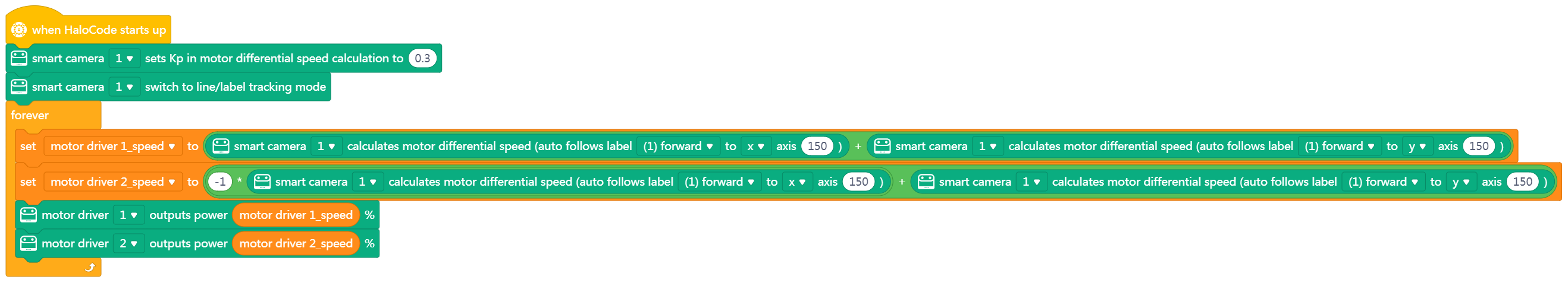
19. smart camera [INDEX] calculates motor differential speed (auto follows color block[SIGN] to [COORD] axis [NUM] )

Reports the motor differential speed required for making Halocode follow the specified color block while keeping the color block in the specified x- or y-coordinate of the captured image
How to Use
The motor differential speed is positively related to Kp. A greater Kp value indicates a greater motor differential speed.
Value range of the motor differential speed: 0–100
The following figure shows the coordinates of an image captured by a smart camera.
X-axis coordinate range: 0–320
Y-axis coordinate range: 0–240
Example
After you start Halocode, it follows color block 1.
Note: Ensure that you have connected two motor drivers and motors to Halocode, constructed a motion structure such as wheels for it, and added the Motor Driver extension for programming Halocode.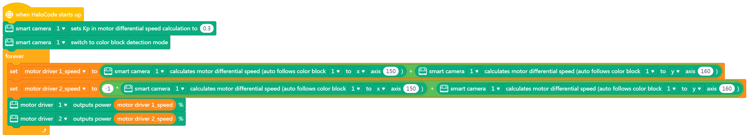
20. smart camera [INDEX] calculates motor differential speed(targets the line-following section)

Reports the motor differential speed required for keeping the line to be followed in the center of the captured image
How to Use
The motor differential speed is positively related to Kp. A greater Kp value indicates a greater motor differential speed.
Value range of the motor differential speed: 0–100
Example
After you start Halocode, it follows the line.
Note: Ensure that you have connected two motor drivers and motors to Halocode, constructed a motion structure such as wheels for it, and added the Motor Driver extension for programming Halocode.
21. smart camera[INDEX]targets area near color block [SIGN] to[COORD] axis [NUM] ?

Determines whether the specified color block is located near the specified x- or y-coordinate of the captured image
How to Use
The following figure shows the coordinates of the image captured by a smart camera.
X-axis coordinate range: 0–320
Y-axis coordinate range: 0–240
Example
After you start Halocode, if color block 1 is located near the x-coordinate of 150, motor drivers 1 and 2 output power for one second.
Note: Ensure that you have connected two motor drivers and motors to Halocode, constructed a motion structure such as wheels for it, and added the Motor Driver extension for programming Halocode.
22. smart camera[INDEX] targets area near label[LABEL] to [COORD] axis [NUM] ?

Determines whether the specified barcode is located near the specified x- or y-coordinate of the captured image
How to Use
The following figure shows the coordinates of the image captured by a smart camera.
X-axis coordinate range: 0–320
Y-axis coordinate range: 0–240
Example
After you start Halocode, if barcode 1 is located near the x-coordinate of 150, motor drivers 1 and 2 output power for one second.
Note: Ensure that you have connected two motor drivers and motors to Halocode, constructed a motion structure such as wheels for it, and added the Motor Driver extension for programming Halocode.

若有收获,就点个赞吧
0 人点赞
