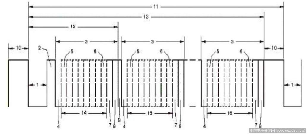

空闲位:没有DMX512数据包输出时,总线保持高电平
BREAK: 数据包的开始报头,维持88us的低电平。
MAB: 8us的高电平
Startcode:起始码:表示通道数据流的开始。
第N帧:通道n的调光数据。
STM32实现DMX512协议
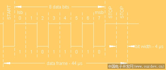
根据波特率可以知道,位时间是4us,11位数据供需要44us的时间。
当然对于标准的512协议是需要break和mark after break 帧的,break是一个92us的低电平,而
mark after break是一个12us的高电平,如下图所示。
根据上面的图片(缺失了起始码,下图补上),512协议必须有break和mark,但是在我们通常的
非标准收发中,检测break和mark相对比较困难,如果非要做,耗费的资源也比较多,比如定时器
计时,中断等等。如果不是做标准控制器的,完全可以另辟蹊径。

每一串数据的开始都要有一个起始码,也称复位码,其数据为0,但是从开始位数至第十位是0,
用来声明数据传输开始,随后包含1-512个数据,也称调光数据,其是标准的数据帧,所以第十位
是1,所以我们可以根据这个第十位来进行做文章。大家都知道,一般的单片机,像51,avr等都
是支持8-9位数据发送的,所以我们就是用9位数据,1位停止位,无校验位,通过检测检测第十
位,也就是所谓的RB8来进行数据的接收与传输,不需要发送break和mark。
1、初始化
串口设为 9位数据,1停止位,无校验位,波特率250000。
void USART1_Configuration(void) 2 {USART_InitTypeDef USART_InitStructure;USART_InitStructure.USART_BaudRate = 250000;USART_InitStructure.USART_WordLength = USART_WordLength_9b;USART_InitStructure.USART_StopBits = USART_StopBits_1;USART_InitStructure.USART_Parity = USART_Parity_No;USART_InitStructure.USART_HardwareFlowControl = USART_HardwareFlowControl_None;USART_InitStructure.USART_Mode = USART_Mode_Rx | USART_Mode_Tx;/* Configure USART1 */USART_Init(USART1, &USART_InitStructure);/* Enable USART1 Receive and Transmit interrupts */USART_ITConfig(USART1, USART_IT_RXNE, ENABLE);//USART_ITConfig(USART1, USART_IT_TC, ENABLE);/* Enable the USART1 */USART_Cmd(USART1, ENABLE);}
注意在初始化串口的时候别忘了485芯片设为发送状态
2、数据包的发送
**
1 void DMX_SendPacket(void){pDMX_buf = 0;while (pDMX_buf <= 512) //1-512{/* send data packet to slaves*/if(USART1->SR & (1<<6)){/*发送起始码 00*/if (0 == pDMX_buf){USART1->DR = ((USART1->DR) & 0xfe00); //第九位置0}else{USART1->DR = 0x0100 | DMX_buf[pDMX_buf]; //第九位置1}pDMX_buf++;}}}
3、数据包的接收
**
void USART1_Configuration(void){USART_InitTypeDef USART_InitStructure;USART_InitStructure.USART_BaudRate = 250000;USART_InitStructure.USART_WordLength = USART_WordLength_9b;USART_InitStructure.USART_StopBits = USART_StopBits_1;USART_InitStructure.USART_Parity = USART_Parity_No;USART_InitStructure.USART_HardwareFlowControl = USART_HardwareFlowControl_None;USART_InitStructure.USART_Mode = USART_Mode_Rx | USART_Mode_Tx;/* Configure USART1 */USART_Init(USART1, &USART_InitStructure);/* Enable USART1 Receive and Transmit interrupts */USART_ITConfig(USART1, USART_IT_RXNE, ENABLE);//使能接收中断//USART_ITConfig(USART1, USART_IT_TC, ENABLE);/* Enable the USART1 */USART_Cmd(USART1, ENABLE);}void NVIC_Configuration(void){NVIC_InitTypeDef NVIC_InitStructure;#ifdef VECT_TAB_RAM/* Set the Vector Table base location at 0x20000000 */NVIC_SetVectorTable(NVIC_VectTab_RAM, 0x0);#else /* VECT_TAB_FLASH *//* Set the Vector Table base location at 0x08000000 */NVIC_SetVectorTable(NVIC_VectTab_FLASH, 0x0);#endif//设置优先级分组:先占优先级和从优先级 ,先占优先级0位,从优先级4位NVIC_PriorityGroupConfig(NVIC_PriorityGroup_0);/* Enable the USART1 Interrupt */NVIC_InitStructure.NVIC_IRQChannel = USART1_IRQn;NVIC_InitStructure.NVIC_IRQChannelPreemptionPriority = 0;NVIC_InitStructure.NVIC_IRQChannelSubPriority = 1;NVIC_InitStructure.NVIC_IRQChannelCmd = ENABLE;NVIC_Init(&NVIC_InitStructure);}void USART1_IRQHandler(void){uint16_t UDR;static uint16_t RXB8;static uint16_t pDMX_buf = 0; //数据指针static uint8_t fDMX_buf_right = 0;//接收数据if(USART_GetITStatus(USART1, USART_IT_RXNE) != RESET)//USART_FLAG_RXNE{//USART_ClearITPendingBit(USART1,USART_FLAG_RXNE);UDR = USART_ReceiveData(USART1);RXB8 = (UDR & 0x0100);if (RXB8 == 0) //复位信号{if (!UDR){fDMX_buf_right = 1;//接收数据正确pDMX_buf = 1; //直接接收第一个数据 不保存第0个数据。}}else //rb8 =1 pDMX_buf=1 调光数据{if (1 == fDMX_buf_right){DMX_buf[pDMX_buf++] = (u8)UDR;//接收到512个数据if (pDMX_buf > 512){fDMX_buf_right = 0;tim_update = SET; //更新调光数据}}}}}

