实验拓扑
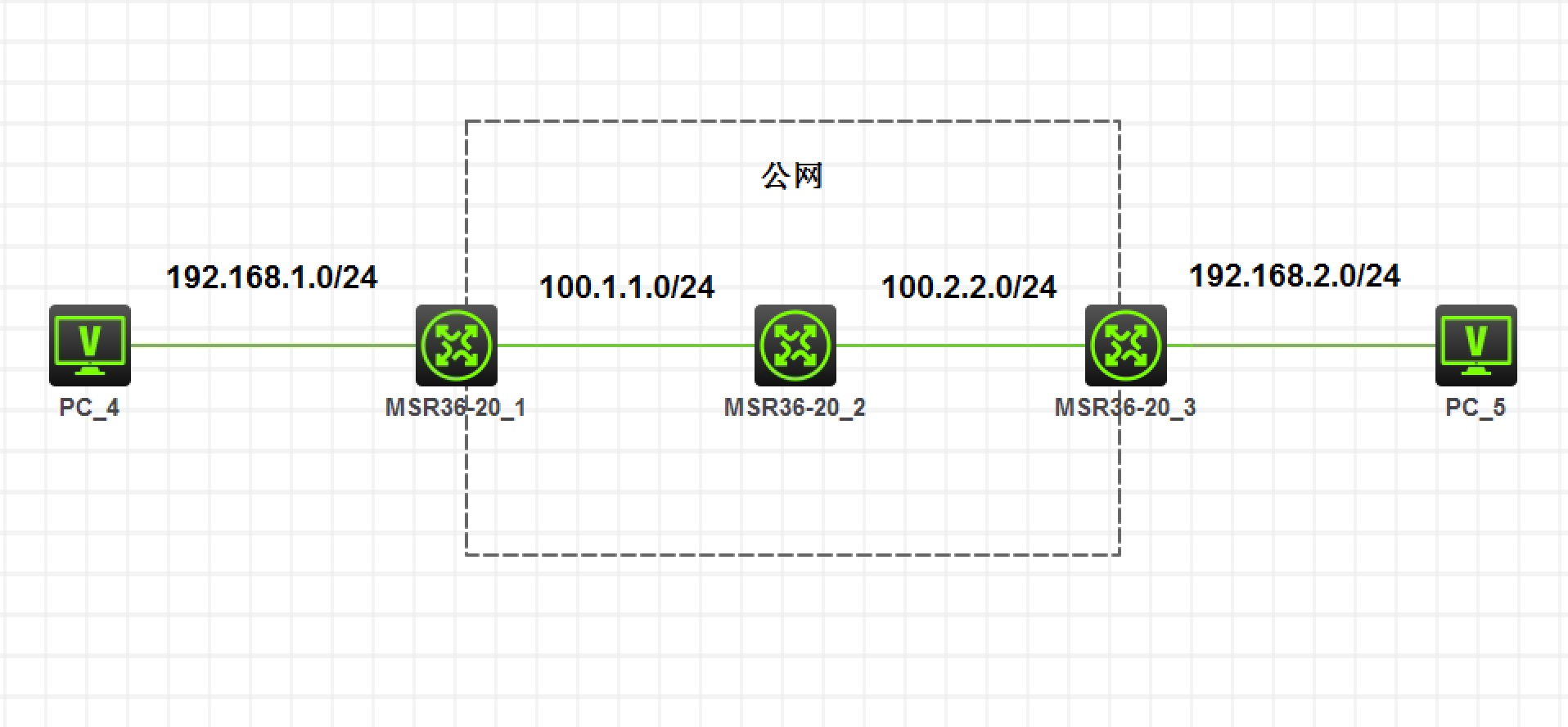
图 1-1
注:如无特别说明,描述中的 R1 或 SW1 对应拓扑中设备名称末尾数字为 1 的设备,R2 或 SW2 对应拓扑中设备名称末尾数字为 2 的设备,以此类推;另外,同一网段中,IP 地址的主机位为其设备编号,如 R3 的 g0/0 接口若在 192.168.1.0/24 网段,则其 IP 地址为 192.168.1.3/24,以此类推
实验需求
- 按照图示配置 IP 地址
- 在 R1 和 R3 上配置默认路由连通公网
- 在 R1 和 R3 上配置 IPsec VPN,使两端私网可以互相访问
实验解法
- 配置 IP 地址部分略
- 配置默认路由部分略
- 在 R1 和 R3 上配置 IPsec VPN,使两端私网可以互相访问
步骤 1:在 R1 上创建感兴趣流,匹配两端私网地址网段(ACL 3101,定义要保护由子网10.1.1.0/24去子网10.1.2.0/24的数据流。也可以允许全部IP:rule permit ip source any destination any)
[R1]acl advanced 3000[R1-acl-ipv4-adv-3000]rule per ip source 192.168.1.0 0.0.0.255 destination 192.168.2.0 0.0.0.255
步骤 2:在 R1 上创建 IKE 提议,配置验证模式为预共享密钥,并配置加密算法
/* 创建IKE方案 */[R1]ike proposal 1/* 配置IKE安全提议的认证方式 */[R1-ike-proposal-1]authentication-method pre-share/* 配置IKE安全提议的加密算法 */[R1-ike-proposal-1]encryption-algorithm aes-cbc-128
步骤 3:在 R1 上创建预共享密钥
/* 创建IKE预共享密钥名称为r3 */[R1]ike keychain r3/* 配置与IP地址为2.2.2.2的对端使用的预共享密钥为明文123456 */[R1-ike-keychain-r3]pre-shared-key address 100.2.2.3 key simple 123456
步骤 4:在 R1 上创建 IKE Profile,指定本端和对端公网地址,并调用预共享密钥和 IKE 提议
/* 配置IKE安全配置文件 */[R1]ike profile r3/* 指定要使用的密钥 */[R1-ike-profile-r3]keychain r3/* 指定本端身份(即本设备公网口的IP地址)(可以配置也可以不配置 使用模版时 不配置这条) */[R1-ike-profile-r3]local-identity address 100.1.1.1/* #配置匹配对端身份的规则为IP地址100.2.2.3 (这里可以匹配多个对端身份) */[R1-ike-profile-r3]match remote identity address 100.2.2.3/* 为IKE配置文件指定IKE建议 */[R1-ike-profile-r3]proposal 1/* 附:匹配多个对端身份 ip地址为 2.2.2.2 到 2.2.2.4[DeviceA-ike-profile-profile1] match remote identity address range 2.2.2.2 2.2.2.4 */
步骤 5:在 R1 上创建IPsec 转换集,配置加密和验证算法。由于工作模式默认是隧道模式,且协议默认使用 ESP,所以无需配置
[R1]ipsec transform-set r3/ ** 配置ESP协议采用的加密算法为128比特的AES,认证算法为HMAC-SHA1 (也有多种选择 按自己的需求选择) ** /[R1-ipsec-transform-set-r3]esp authentication-algorithm sha1[R1-ipsec-transform-set-r3]esp encryption-algorithm aes-cbc-128
步骤 6:在 R1 上创建 IPsec 策略,调用上述配置
/*创建一条IKE协商方式的IPsec安全策略,名称为r3,顺序号为1*/[R1]ipsec policy r3 1 isakmp/* 指定引用ACL3000 */[R1-ipsec-policy-isakmp-r3-1]security acl 3000/* 指定引用的IKE profile为r3 */[R1-ipsec-policy-isakmp-r3-1]ike-profile r3/* 指定引用的安全提议为r3 */[R1-ipsec-policy-isakmp-r3-1]transform-set r3/** 配置IPsec隧道的对端IP地址为100.2.2.3 **/[R1-ipsec-policy-isakmp-r3-1]remote-address 100.2.2.3
步骤 7:在 R1 的公网接口上下发 IPsec 策略
/* 在接口GigabitEthernet2/1/1上应用IPsec安全策略map1 */[R1-GigabitEthernet0/0]ipsec apply policy r3
步骤 8:在 R3 上完成 IPsec 相关配置,方法和命令与 R1 一致,本端和对端地址对调即可
效果测试:在 PC4 上 Ping PC5,可以直接 Ping 通
<PC4>ping 192.168.2.5Ping 192.168.2.5 (192.168.2.5): 56 data bytes, press CTRL_C to break56 bytes from 192.168.2.5: icmp_seq=0 ttl=253 time=26.000 ms56 bytes from 192.168.2.5: icmp_seq=1 ttl=253 time=29.000 ms56 bytes from 192.168.2.5: icmp_seq=2 ttl=253 time=34.000 ms56 bytes from 192.168.2.5: icmp_seq=3 ttl=253 time=52.000 ms56 bytes from 192.168.2.5: icmp_seq=4 ttl=253 time=25.000 ms
注:穿透NAT需按规则,书写感兴趣流
如
[R1]acl advanced 3000[R1-acl-ipv4-adv-3000]rule per ip source 192.168.1.0 0.0.0.255 destination 192.168.2.0 0.0.0.255/* 这个用于NAT,首先把IPSec的流给deny,让正常访问公网的包可以使用 */[R1]acl advanced 3001[R1-acl-ipv4-adv-3001]rule 0 deny ip source 192.168.1.0 0.0.0.255 destination 192.168.2.0 0.0.0.255[R1-acl-ipv4-adv-3001]rule 5 per ip source 192.168.1.0 0.0.0.255
NAT的优先级大于IPSec
| display ipsec sa [ brief | count | interface interface-type interface-number | { ipv6-policy | policy } policy-name [ seq-number ] | profile policy-name | remote [ ipv6 ] ip-address ] | ||
|---|---|---|
| display ipsec tunnel { brief | count | tunnel-id tunnel-id } |

若有收获,就点个赞吧
0 人点赞
