In the device mode, some hardware devices can use variables, events or messages to achieve the effect of interacting with the stage. Below, an example will show how to use these two modes for mixed programming.
Take Grove Zero example project, reversing radar as an example, to see how to make the device mode and stage mode work together with the help of variables to realize the program of displaying the effect of reversing radar on computer screen through hardware ranging and alarm.
Project Overview
The reversing radar uses 3 Grove Zero modules: Main Board BLE, Buzzer, Ultrasonic Sensor. The modules and connection methods are shown in the following figure: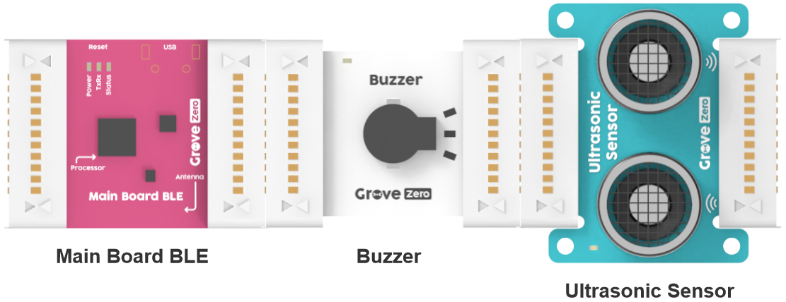
The hardware prototype of the car with reversing radar is shown in the following figure: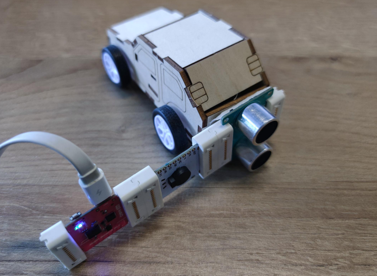
The desired effect is shown below. The stage in stage mode will display the current alarm status and Distance value in real time according to the measurement results of the hardware equipment.
 The functions of the parking sensor are described as follows:
• The alarm status is 3: When the distance close to the object is greater than 50 cm, neither the Buzzer nor the radar display
• The alarm state is 2: When the distance to the object is between 20-50 cm, the Buzzer will beep at low frequency and the radar will display green
• The Alarm Status is 1: When the distance to the object is 20~5cm, the Buzzer will beep quickly and the radar will display orange
• The alarm state is 0: when the object is less than 5 cm, the Buzzer will beep at high frequency and the radar will display red
Project steps
1. Use Codecraft to program the device
Open Codecraft to start programming, and make sure that the current device is Grove Zero in device mode.
The program created two variables applicable to all roles: “Alarm Status” and “Distance”, as shown in the figure below.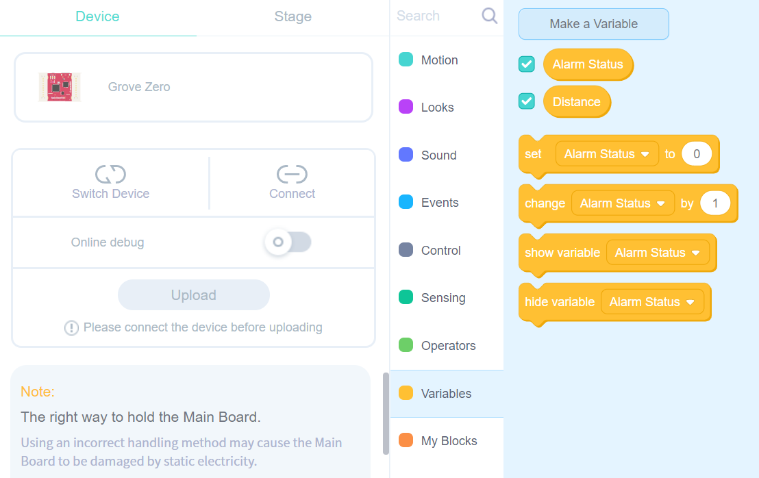
The program in the device mode obtains the distance value through the Ultrasonic Sensor, and assigns the value to the variable “Distance”. Then through a series of conditional statements, the value of “Alarm Status” is determined according to the distance value. At the same time, set different Buzzer sound effects for different “Alarm Status”.
Modify the project name to “reversing radar”, and the programmed program is shown in the figure below.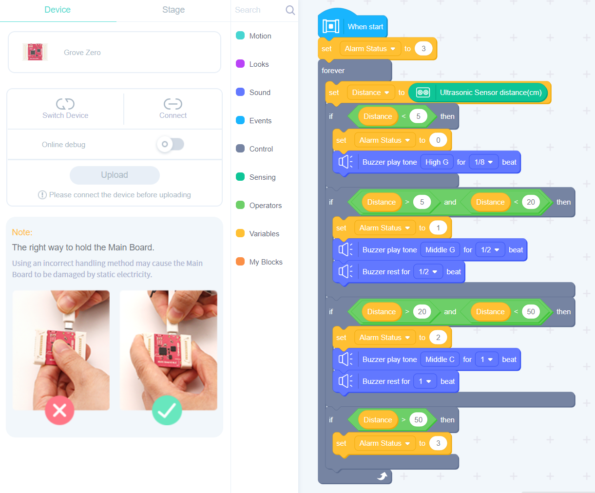
2. Connecting equipment and program testing
As shown in the figure below, connect the Main Board BLE, Buzzer and Ultrasonic Sensor, and then connect the Main Board BLE to the PC.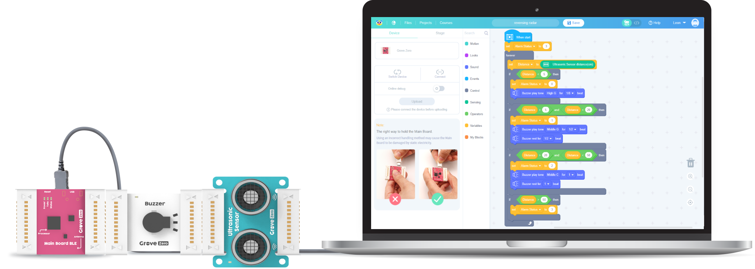
In Codecraft, first Connect and start Online debug. Then click on the program in the programming area, and a gold border appears around the program, which means that it has entered the Online debug state.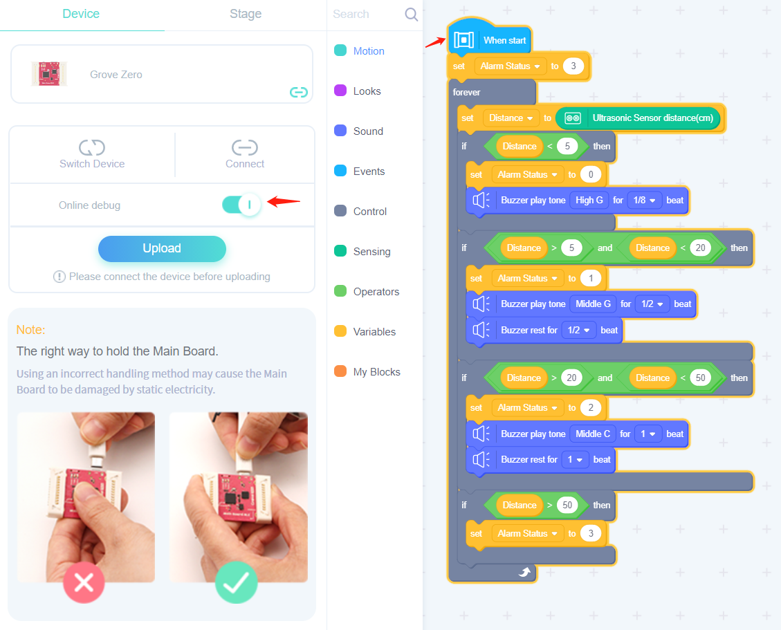
As shown in the figure below, when the red car approaches the ultrasonic sensor, you can hear the sound changes with distance through the Buzzer.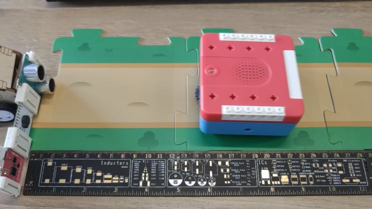
3. Material preparation for stage mode reversing radar display
There are four files for the display of the reversing radar in the stage mode, as shown in the figure below.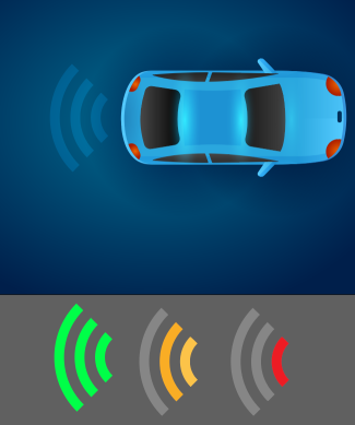
These 4 files are saved in SVG format and can be downloaded here: reversing radar_image.zip
Enter the stage mode of the “reversing radar” program and place the sprite and background separately.
You need to delete the default owl sprite and add a new reversing radar status pattern. As shown in the figure below, add three state materials to a sprite.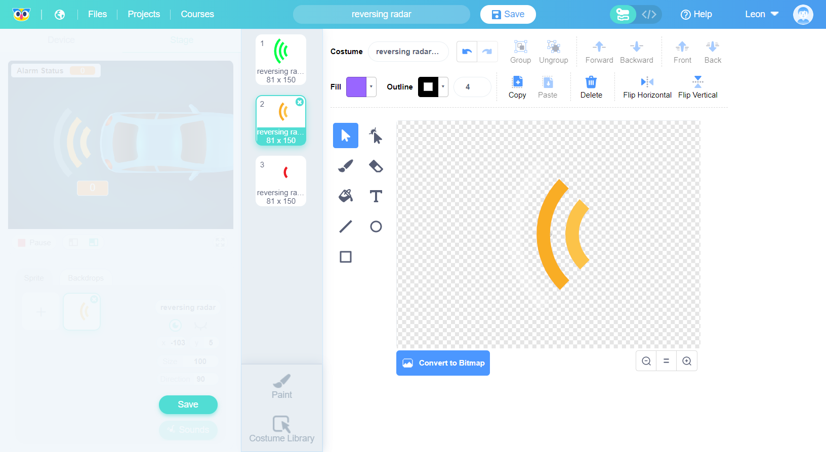
The effect after replacing the background.
4. Programming in stage mode
In the stage mode, you can see the variables created in the device mode.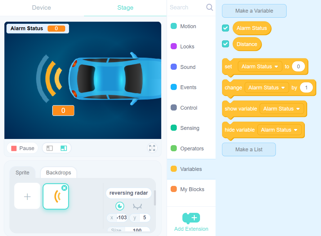
These variables will also be displayed in the stage mode. You can drag the “Distance” variable from the upper left corner to the middle of the scene and set it to large readout. The effect is shown in the figure below.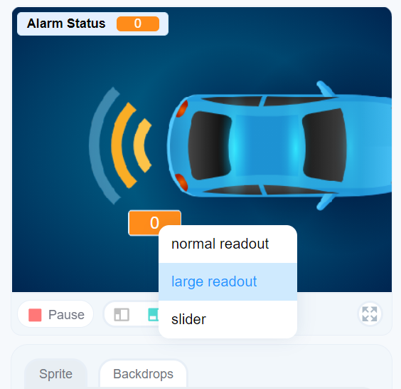
Finally complete the program in stage mode, as shown in the figure below.
Now all programming has been completed.
5. Program testing in mixed mode
Return to the Device mode, start Online debug and run the program, refer to step 2 for specific operations. At this time, the hardware device has entered the running state.
In the Stage mode, click the  button below the stage, or click the program directly, and you can see the golden border around the program blocks - now the program in the stage mode has also entered the running state, as shown in the figure below.
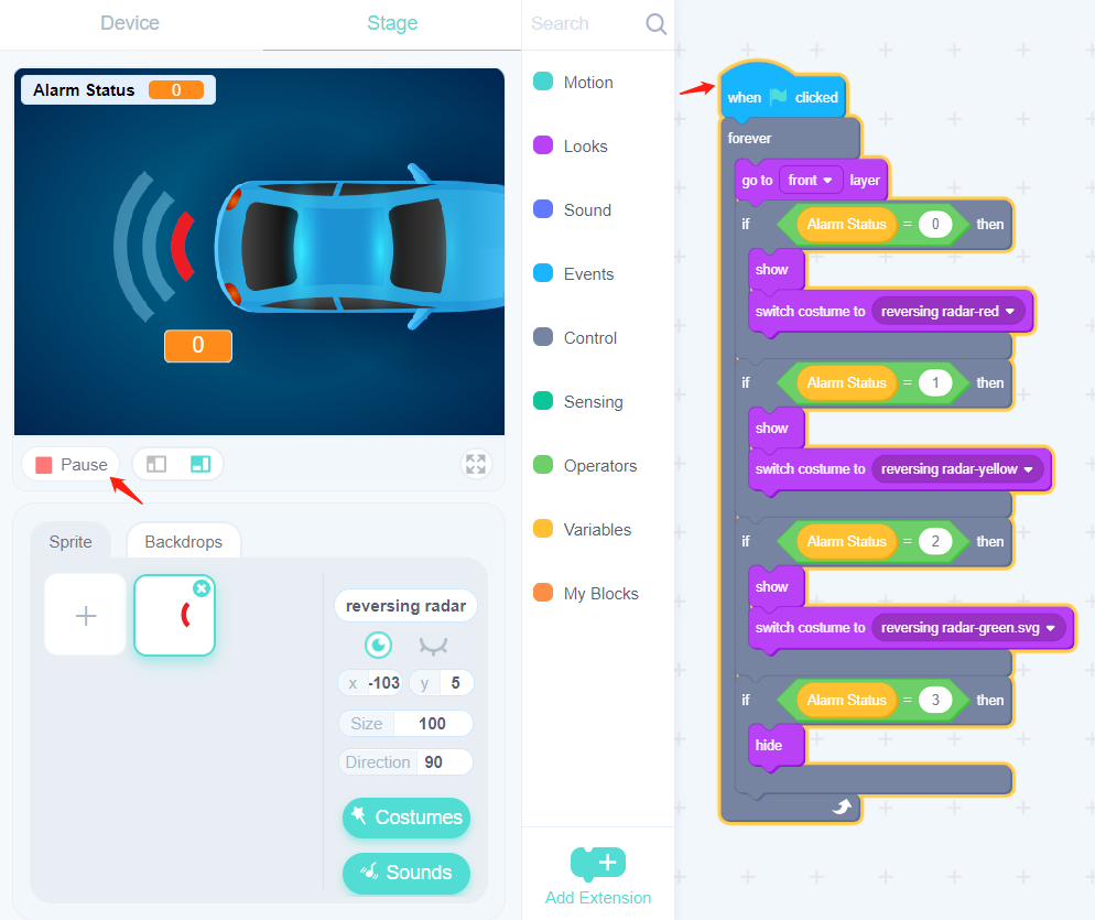
Test the running effect in mixed mode.
Project program download
Get the program source files of the reversing radar project here: reversing radar-cdc.zip

若有收获,就点个赞吧
0 人点赞
