写在前面
本教程展示了如何使用优化指令将初始RTL实现转换为低面积和高吞吐量实现。
Lab1
HLS基本步骤:
验证C代码。
创建并综合成一个解决方案。
验证RTL并打包IP。
IMPORTANT: In this lab there is only one C design file. When there are multiple C files to be
synthesized, you must add all of them to the project at this stage. Any header files that exist in the local
directory lab1 are automatically included in the project. If the header resides in a different location,
use the Edit CFLAGS button to add the standard gcc/g++ search path information (for example, -I
头文件只需要放在对应的文件夹,不需要专门添加。
testbench中需要添加.dat文件,否则因为无法找到数据文件而失败
Latency vs Interval
The design has a latency of 34-clock cycles: it takes 34 clocks to output the results.
任一输入到其输出的时间
The interval is 34 clock cycles: the next set of inputs is read after 34 clocks. The design is not pipelined. The next execution of this function (or next transaction) can only start when the current transaction completes.
两个输入/两个输出之间的间隔
总延迟(34)大于循环延迟(33)的一个时钟周期。 输入和退出循环需要一个时钟周期(在这种情况下,当循环完成时,设计完成,因此没有退出周期)。
资源利用率是估计的,因为RTL综合可能能够执行额外的优化,这些数字可能在RTL综合之后发生变化。
标量输入参数x被实现为没有I/O协议(ap_none)的数据端口。
Lab2
使用Tcl交互。
CAUTION! When copying the RTL results from a Vivado HLS project, you must use the RTL from the
impl directory. Additional processing is performed by Vivado HLS during export_design before you
can use this RTL in other design tools.
复制时从impl文件夹下复制
Lab2将在GUI中实现的功能转移到Tcl,也给出了一种获得Tcl代码的方法。
Lab3
使用优化指令优化设计。 这个实验创建多个版本的RTL实现,并比较不同的解决方案。
指定使用单端口块RAM资源实现数组c。
由于数组c在函数参数列表中,因此在函数之外,因此自动创建一组数据端口,以访问RTL实现之外的单端口块RAM。

更改后的策略如右图所示。修改后的结果见下图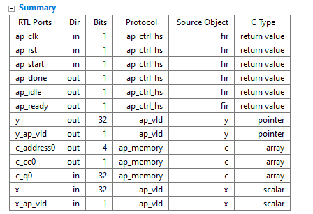
(和教程不太一样)#HLS代码上次添加,%HLS代表本次添加
在此设计上执行额外的优化,还有优化空间。
例如,您可以使用流水线来进一步提高吞吐量并降低间隔。
总结
在本教程中,您学习了:
在GUI和TCL环境中创建Vivado高级综合项目。
执行HLS设计流程中的主要步骤。
创建并使用TCL文件运行Vivado HLS。
创建新的解决方案,添加优化指令,并比较不同解决方案的结果。

若有收获,就点个赞吧
0 人点赞
