- ASA 5500-X Series Firewalls
- ASA 5585-X Adaptive Security Appliance
- ASA 5585-X SSP-10 With Add-on SSP-10
- ASA 5585-X SSP-40 With Add-on SSP-40
ASA 5500-X Series Firewalls
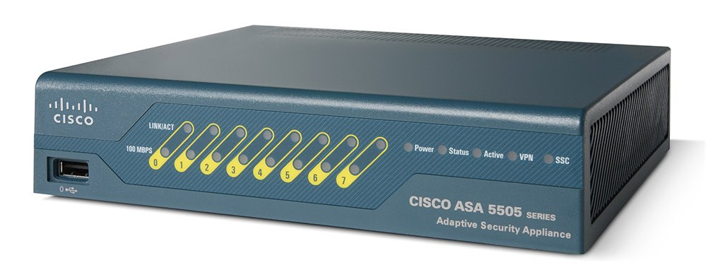
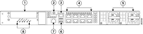
ASA 5505 Adaptive Security Appliance
前面板LED与端口
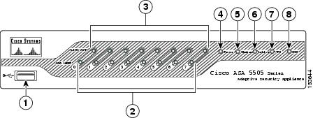
| 1 | USB 2.0 interface | 5 | Status |
|---|---|---|---|
| 2 | 100 Mbps | 6 | Active |
| 3 | LINK/ACT LEDs | 7 | VPN |
| 4 | 8 | SSC |
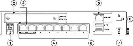
| 1 | Power 48VDC | 5 | Console port |
|---|---|---|---|
| 2 | SSC slot | 6 | USB 2.0 interface |
| 3 | Network interface LEDs | 7 | Reset button |
| 4 | Network interfaces1 | 8 | Lock slot |
- 端口6、7 可以提供15瓦的PoE供电
Set up the terminal as follows: 9600 baud (default), 8 data bits, no parity, 1 stop bits, and Flow Control (FC) = Hardware.
Adaptive Security Appliance (ASA) Software Latest Release
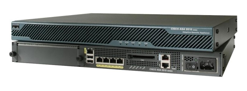
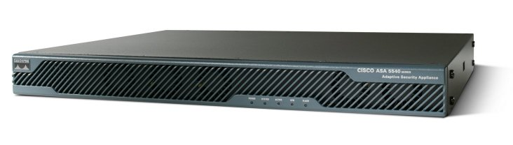
ASA 5510 && 5520 && 5540 Adaptive Security Appliance

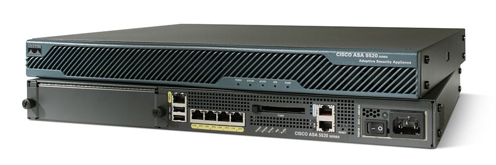
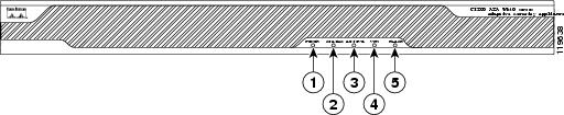
前面板LED
| LED | Color | State | Description | |
|---|---|---|---|---|
| 1 | Power | Green | On | The system has power. |
| 2 | Status | Green | Flashing | The power-up diagnostics are running or the system is booting. |
| Solid | The system has passed power-up diagnostics. | |||
| Amber | Solid | The power-up diagnostics have failed. | ||
| 3 | Active | Green | Solid | This unit is the Active unit in the failover pair. |
| Amber | Solid | This unit is the Standby unit. | ||
| 4 | VPN | Green | Solid | A VPN tunnel has been established. |
| 5 | Flash | Green | Solid | The CompactFlash is being accessed. |
后面板接口
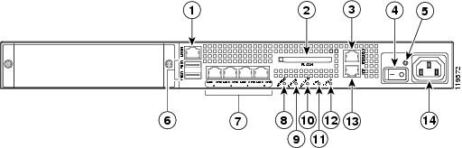
| 1 | Management port(带外管理口) | 6 | USB 2.0 interfaces(不支持) | 11 | VPN LED |
|---|---|---|---|---|---|
| 2 | External CompactFlash slot | 7 | Network interfaces | 12 | Flash LED |
| 3 | Serial Console port | 8 | Power indicator LED | 13 | AUX port(不起作用) |
| 4 | Power switch | 9 | Status indicator LED | 14 | Power connector |
| 5 | Power indicator LED | 10 | Active LED |
ASA 5550 Adaptive Security Appliance
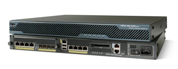
前面板与5510,5520 相同
后面板LED 与 端口
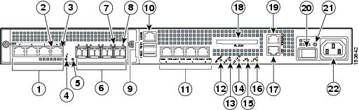
| 1 | RJ-45 ports | 9 | USB 2.0 interfaces | 17 | AUX port |
|---|---|---|---|---|---|
| 2 | RJ-45 Link LED | 10 | Management port (仅管理流量) | 18 | External CompactFlash slot |
| 3 | RJ-45 Speed LED | 11 | Network interfaces | 19 | Serial Console port |
| 4 | Power LED | 12 | Power indicator LED | 20 | Power switch |
| 5 | Status LED | 13 | Status indicator LED | 21 | Power indicator LED |
| 6 | SFP ports | 14 | Active LED | 22 | Power connector |
| 7 | SFP Link LED | 15 | VPN LED | ||
| 8 | SFP Speed LED | 16 | Flash LED |
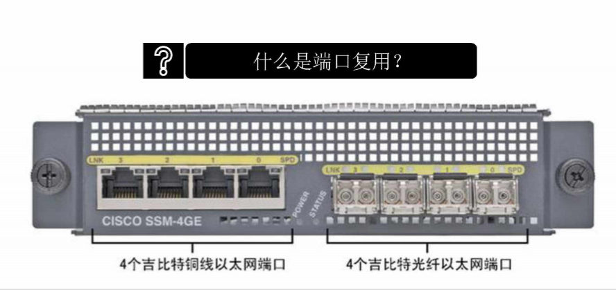
4GE SSM LED
| LED | Color | State | Description | |
|---|---|---|---|---|
| 2, 7 | LINK | Green | Solid Flashing |
There is an Ethernet link. There is Ethernet activity. |
| 3, 8 | SPEED | Off Green Amber |
10 MB 100 MB 1000 MB (GigE) |
There is no network activity. There is network activity at 100 Mbps. There is network activity at 1000 Mbps. |
| 4 | POWER | Green | On | The system has power. |
| 5 | STATUS | Green Green Amber |
Flashing Solid Solid |
The system is booting. The system booted correctly. The system diagnostics failed. |
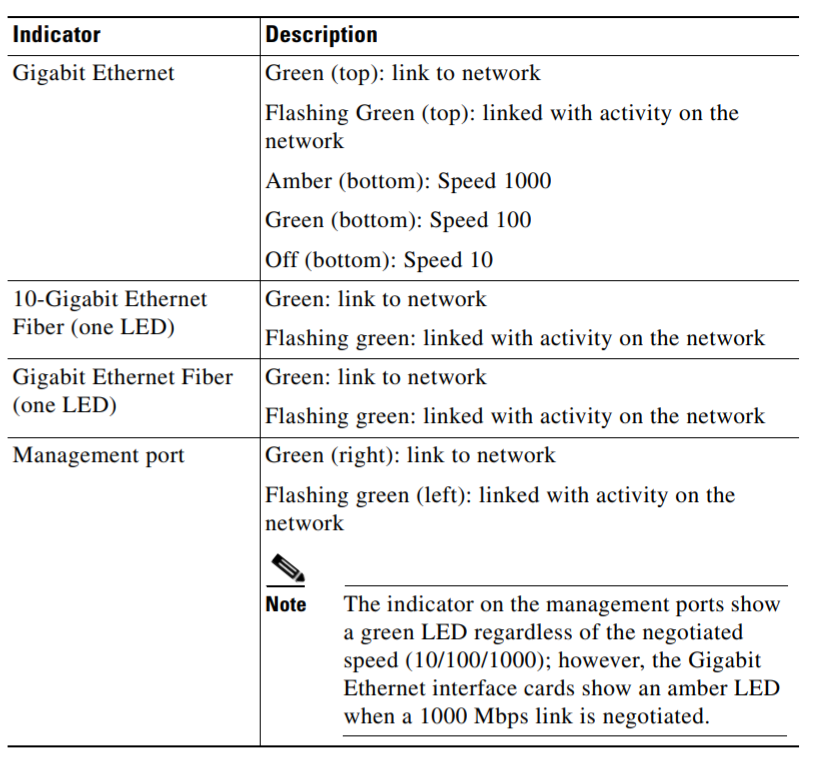
链接和速度LED
| Indicator | Color | Description |
|---|---|---|
| Left side | Solid green Green flashing |
Physical link Network activity |
| Right side | Not lit Green Amber |
10 Mbps 100 Mbps 1000 Mbps |
ASA 5512-X 5515-X 5525-X Adaptive Security Appliance
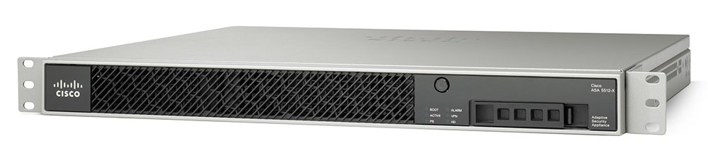
前面板端口
| LED | Description | |
|---|---|---|
| 1 | Power button | A soft switch that turns the system on and off. Once pressed, the button stays in the “on” position: - On—The power symbol on the button is lit. |
- Off—The power symbol on the button is dark.
For information about the power state, see the Power Supply Considerations. |
| 2 | Hard-disk release button | Releases the hard disk from the device. |
| 3 | Alarm | System operating status:
- Off—Normal operating system function.
- Solid amber—Critical Alarm indicating one or more of the following:
– a major failure of a hardware or software component.
–an over-temperature condition.
–power voltage is outside of the tolerance range.
Note : May appear red on some devices. |
| 4 | VPN | VPN tunnel status:
: May appear red on some devices. |
| 4 | VPN | VPN tunnel status:
- Solid green—VPN tunnel is established.
- Off—No VPN tunnel established.
|
| 5 | HD | Hard Disk Drive status:
- Flashing green—Proportioned to read/write activity.
- Solid amber—Hard-disk drive failure.
- Off—No hard-disk drive present.
|
| 6 | PS | Power supply status |
| 7 | Active | Status of the failover pair:
- Solid green—Failover pair is operating normally.
- Off—Failover is not operational or this is the secondary unit in the failover pair.
|
| 8 | Boot | Power-up diagnostics:
- Flashing green—Power-up diagnostics are running, or system is booting.
- Solid green—System has passed power-up diagnostics.
- Off—Power-up diagnostics are not operational.
|
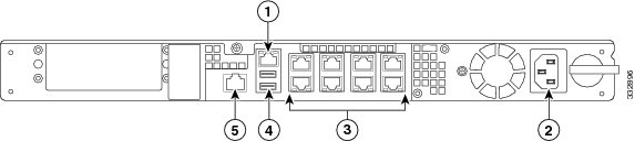
ASA 5512-X 5515-X 后面板
| LED | Description | |
|---|---|---|
| 1 | Management 0/0 interface | The GigabitEthernet interface that is restricted to management use only. Connect with an RJ-45 cable. |
| 2 | Power supply | The chassis power supply. |
| 3 | GigabitEthernet data interfaces (0/0 through 0/5) | The 6 on-board data interfaces. Connect with an RJ-45 cable. The top row port numbers are (from left to right) 5, 3, 1. The bottom row port numbers are (from left to right) 4, 2, 0. |
| 4 | USB Ports | The two USB standard ports. (See the Internal and External USB Flash Drives.) |
| 5 | Console port | The RS-232 serial console port used to directly connect a computer to the ASA. Connect with an RJ-45 cable. |
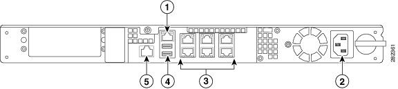
ASA 5525-X 后面板
| LED | Description | |
|---|---|---|
| 1 | Management 0/0 interface | The GigabitEthernet interface that is restricted to management use only. Connect with an RJ-45 cable. |
| 2 | Power supply | The chassis power supply. |
| 3 | GigabitEthernet data interfaces (0/0 through 0/7) | The 8 on-board data interfaces. Connect with an RJ-45 cable. The top row port numbers are (from left to right) 7, 5, 3, 1. The bottom row port numbers are (from left to right) 6, 4, 2, 0. |
| 4 | USB Ports | The two USB standard ports. (See Internal and External USB Flash Drives.) |
| 5 | Console port | The RS-232 serial console port used to directly connect a computer to the ASA. Connect with an RJ-45 cable. |
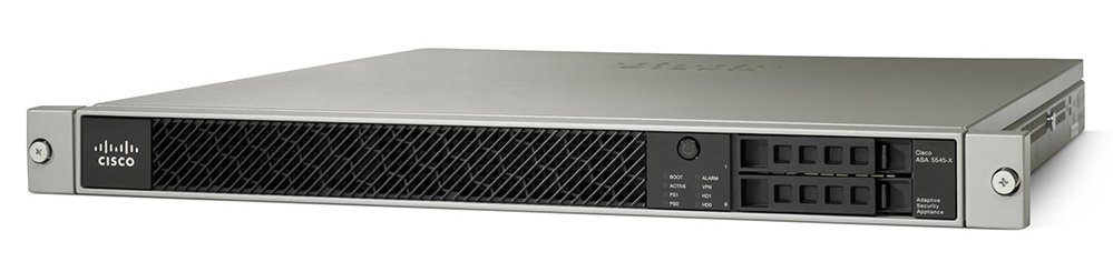
ASA 5545-X 5555-X Adaptive Security Appliance
前面板 LED 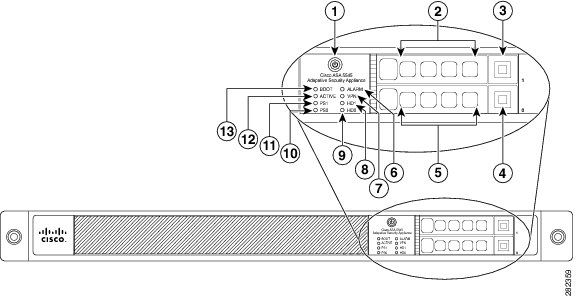
| LED | Description | |
|---|---|---|
| 1 | Power button | A soft switch that turns the system on and off. Once pressed, the button stays in the “on” position: - On—The power symbol on the button is lit. |
- Off—The power symbol on the button is dark.
For information about the power state, see Power Supply Considerations. |
| 2 | Hard-disk slot | Indicates the slot for hard-disk 1. |
| 3 | Hard-disk release button | Releases hard-disk 1 from the device. |
| 4 | Hard-disk release button | Releases hard-disk 0 from the device. |
| 5 | Hard-disk slot | Indicates the slot for hard-disk 0. |
| 6 | Alarm | System operating status:
- Off—Normal operating system function.
- Solid amber—Critical Alarm indicating one or more of the following:
–a major failure of a hardware or software component.
–an over-temperature condition.
–power voltage is outside of the tolerance range.
Note: May appear red on some devices. |
| 7 | VPN | VPN tunnel status:
- Solid green—VPN tunnel is established.
- Off—No VPN tunnel established.
|
| 8 | HD1 | Hard Disk Drive 1 status:
- Flashing green—Proportioned to read/write activity.
- Solid amber—Hard-disk drive failure.
- Off—No hard-disk drive present.
|
| 9 | HD0 | Hard Disk Drive 0 status:
- Flashing green—Proportioned to read/write activity.
- Solid amber—Hard-disk drive failure.
- Off—No hard-disk drive present.
|
| 10 | PS1 | Status of the optional redundant power supply. |
| 11 | PS0 | Status of the primary power supply that ships with the product. |
| 12 | Active | Status of the failover pair:
- Solid green—Failover pair is operating normally.
- Off—Failover pair is not operational.
|
| 13 | Boot | Power-up diagnostics:
- Flashing green—Power-up diagnostics are running, or system is booting.
- Solid green—System has passed power-up diagnostics.
- Off—Power-up diagnostics are not operational.
|
| LED | Description | |
|---|---|---|
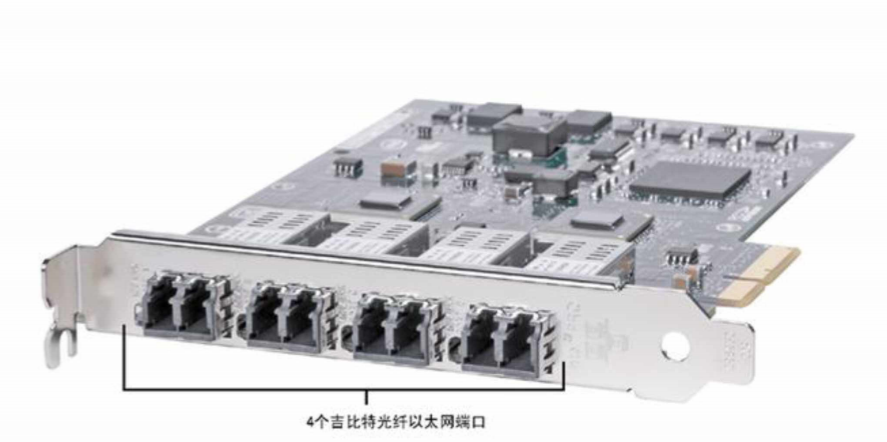
| 1 | I/O slot | Slot for the optional I/O Card. If you have a fiber-optic I/O card, use SFP modules to connect (not included). |
| 2 | Thumbscrew | The screw that tightens and loosens the chassis cover. |
| 3 | Management 0/0 interface | The GigabitEthernet interface that is restricted to management use only. Connect with an RJ-45 cable. |
| 4 | GigabitEthernet data interfaces (0/0 through 0/7) | The 8 on-board data interfaces. Connect with an RJ-45 cable. The top row port numbers are (from left to right) 7, 5, 3, 1. The bottom row port numbers are (from left to right) 6, 4, 2, 0. |
| 5 | Power supplies | Slots for the primary power supply that ships with the device, and the optional redundant power supply. |
| 6 | USB ports | The two USB standard ports. (See Internal and External USB Flash Drives.) |
| 7 | Console port | The RS-232 serial console port used to directly connect a computer to the ASA. Connect with an RJ-45 cable. |
| 8 | Rear panel LEDs | Rear panel LEDs. (See Figure 3 for more information.) |
如果只安装了一个电源,请确保它安装在插槽0(左侧插槽)中,并且插槽1(右侧插槽)上盖有插槽盖。
ASA 5545-X 5555-X 双电源
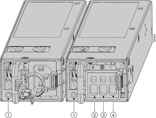
| 1 | Power supply indicator | 2 | DC power supply positive connection |
|---|---|---|---|
| 3 | DC power supply neutral connection | 4 | DC power supply negative connection |
| Indicator Color and State | Description |
|---|---|
| Solid green | Power output is on and within the normal operating range. |
| Blinking green, at the rate of one blink per second | Input power that is within the normal operating range is being supplied, but the Standby switch is in the Standby position (that is, chassis is not On). |
| Solid amber | A power-supply critical event has occurred, and the power supply has shut down. The critical event can be temperature, voltage, current, or fan operating outside the normal operating range. |
| Blinking amber, at the rate of one blink per second | A power-supply warning event has occurred, but the power supply can continue to operate. The warning event can be temperature, voltage, current, or fan operating outside the normal operating range. |
| Off | The power supply is shut down. |
Hardware Specifications
| ASA 5512-X | ASA 5515-X | ASA 5525-X | ASA 5545-X | ASA 5555-X | |
|---|---|---|---|---|---|
| Physical Specifications | |||||
| Form-factor | 1RU, 19-in | 1RU, 19-in | 1RU, 19-in | 1RU, 19-in | 1RU, 19-in |
| Rack mountable | Yes. Brackets included, slide rails optional |
Yes. Brackets included, slide rails optional |
Yes. Brackets included, slide rails optional |
Yes. |
Yes. |
| Dimensions | 1.67x16.7x15.6 in |
1.67x16.7x15.6 in |
1.67x16.7x15.6 in |
1.67x16.7x19.1 in |
1.67x16.7x19.1 in |
| Weight—single power supply | 13.39 lb. | 13.39 lb. | 14.92 lb. | 16.82 lb. | 16.82 lb. |
| Weight—dual power supply | N/A | N/A | N/A | 18.86 lb. | 18.86 lb. |
| Technical Specifications | |||||
| DRAM Memory | 4 GB | 8 GB | 8 GB | 12 GB | 16 GB |
| Internal Flash | 4 GB | 8 GB | 8 GB | 8 GB | 8 GB |
| Power Supply Information | |||||
| Power supply | 400 W | 400W | 400W | 450W | 450W |
| Redundant power supply available | No | No | No | Yes | Yes |
| Operating Conditions | |||||
| Temperature | -5°C to 40°C |
-5°C to 40°C |
-5°C to 40°C |
-5°C to 40°C |
-5°C to 40°C |
| Relative humidity | 90% | 90% | 90% | 90% | 90% |
| Altitude | 10,000 ft. | 10,000 ft. | 10,000 ft. | 10,000 ft. | 10,000 ft. |
| Non-Operating Conditions | |||||
| Temperature | -25°C to 70°C |
-25°C to 70°C |
-25°C to 70°C |
-25°C to 70°C |
-25°C to 70°C |
| Relative humidity | 10% to 90% | 10% to 90% | 10% to 90% | 10% to 90% | 10% to 90% |
| Altitude | 15,000 ft. | 15,000 ft. | 15,000 ft. | 15,000 ft. | 15,000 ft. |
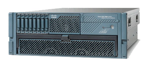
ASA 5580 Adaptive Security Appliance
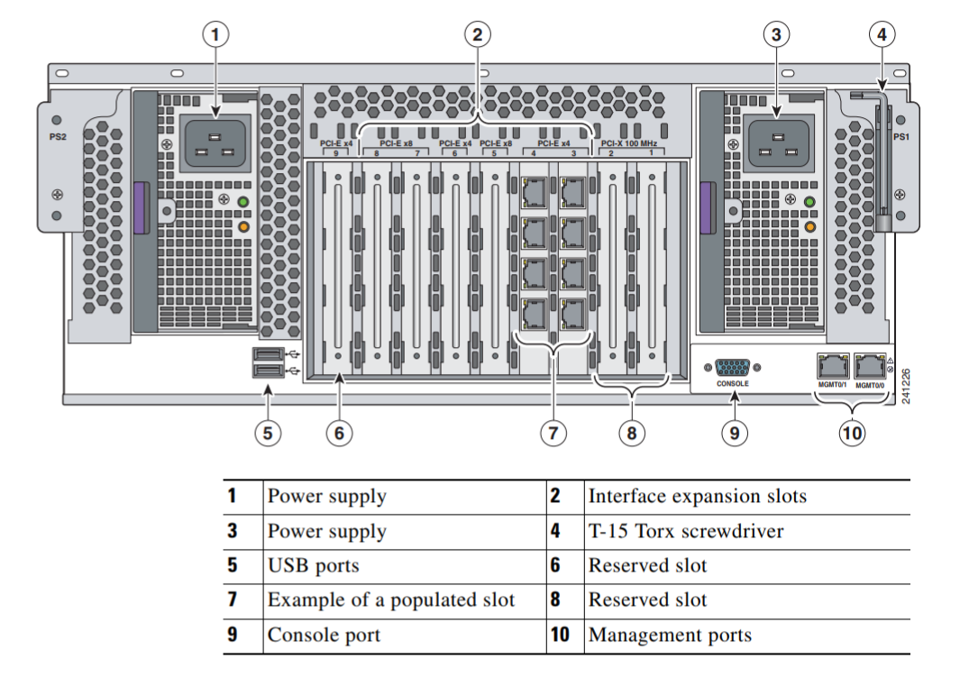

ASA 5580 拓展卡
14_Cisco_ASA_5580_Series_Adaptive_Security_Appliances_Cisco_Phone_Systems_Digitcom_ca_Toronto_Canada.pdf
ASA 5585-X Adaptive Security Appliance
ASA 5585-X with Security Services Processor-10
ASA 5585-X with Security Services Processor-20
ASA 5585-X with Security Services Processor-40
ASA 5585-X with Security Services Processor-60
ASA 5585-X SSP-10 With Add-on SSP-10
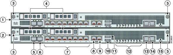
| 1 | SSP or network module (slot 1) | 2 | Core SSP (slot 0) |
|---|---|---|---|
| 3 | Module removal screws | 4 | Reserved hard-disk drive bays in bottom slot; add-on module hard-disk drives in top slot1 |
| 5 | TenGigabitEthernet 0/9 (core SSP in slot 0) TenGigabitEthernet 1/9 (add-on module in Slot 1) (10-Gb fiber, SFP, or SFP+) |
6 | TenGigabitEthernet 0/8 (core SSP in slot 0) TenGigabitEthernet 1/8 (add-on module in slot 1) (10-Gb fiber, SFP, or SFP+) |
| 7 | GigabitEthernet 0/0 through 0/7(core SSP in slot 0) GigabitEthernet 1/0 through 1/7 (add-on module in slot 1) |
8 | Management 0/1 (core SSP in slot 0) Management 1/1 (add-on module in slot 1) (GigabitEthernet RJ45) |
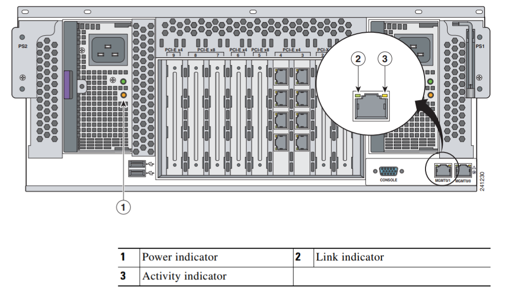
| 9 | Management 0/0 (SSP in slot 0) Management 1/0 (add-on module in slot 1) |
10 | USB port |
| 11 | USB port | 12 | Front panel indicators |
| 13 | Auxiliary port (RJ45)2 | 14 | Console port (RJ45) |
| 15 | Eject3 |
ASA 5585-X SSP-40 With Add-on SSP-40
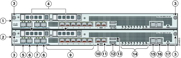
| 1 | Add-on SSP or network module (slot 1) | 2 | Core SSP (slot 0) |
|---|---|---|---|
| 3 | Add-on module removal screws | 4 | Reserved bays for hard-disk drives4 |
| 5 | TenGigabitEthernet 0/9 (core SSP in slot 0) TenGigabitEthernet 1/9 (add-on module in slot 1) (10-Gb fiber, SFP, or SFP+) |
6 | TenGigabitEthernet 0/8 (core SSP in slot 0) TenGigabitEthernet 1/8 (add-on module in slot 1) (10-Gb fiber, SFP, or SFP+) |
| 7 | TenGigabitEthernet 0/7 (core SSP in slot 0) TenGigabitEthernet 1/7 (add-on module in slot 1) (10-Gb fiber, SFP, or SFP+) |
8 | TenGigabitEthernet 0/6 (core SSP in slot 0) TenGigabitEthernet 1/6 (add-on module in slot 1) (10-Gb fiber, SFP, or SFP+) |
| 9 | GigabitEthernet 0/0 through 0/5 (core SSP in slot 0) GigabitEthernet 1/0 through 1/5 (add-on module in slot 1) (from right to left, 1-Gb copper, RJ45) |
10 | Management 0/1 (core SSP in slot 0) Management 1/1 (add-on module in slot 1) (GigabitEthernet RJ45) |
| 11 | Management 0/0 (core SSP in slot 0) Management 1/0 (add-on module in slot 1) (GigabitEthernet RJ45) |
12 | USB port |
| 13 | USB port | 14 | Front panel indicators |
| 15 | Auxiliary port (RJ45)5 | 16 | Console port (RJ45) |
| 17 | Eject6 |
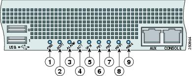
| Figure Label | Indicator | Description |
|---|---|---|
| 1 | PWR | Whether the system is off or on: - Unlit—No power. |
- Green—System has power.
|
| 2 | BOOT | Status of the power-up diagnostics:
- Flashing green—Power-up diagnostics are running, or the system is booting.
- Green—System has passed power-up diagnostics.
- Amber—Power-up diagnostics failed.
|
| 3 | ALARM | Component failure:
- Unlit—No alarm.
- Amber—Critical alarm:
Major failure of hardware component or software module, temperature over the limit, power out of tolerance, or time to remove the module.8
Note May appear red on some units. |
| 4 | ACT | Role of a high-availability (HA) pair:
- Green—The active-mode unit.
- Amber—The standby unit.
|
| 5 | VPN | Whether a VPN tunnel has been established:
- Green—VPN tunnel established.
|
| 6 | PS1 | State of the power-supply module installed on the right:
- Unlit—No power supply module present, or no AC input.
- Green—Power supply module present, on, and good.
- Amber—Power or fan module off, or failed.
|
| 7 | PS0 | State of the power module installed on the left:
- Unlit—No power supply module present, or no AC input.
- Green—Power supply module present, on, and good.
- Amber—Power or fan module off, or failed.
|
| 8 | HDD1 | Indicates activity on the first hard-disk drive:9
- Unlit—No hard-disk drive present.
- Flashing green—Hard-disk drive activity.
- Amber—Hard-disk drive failure.
|
| 9 | HDD2 | Indicates activity on the second hard-disk drive:
- Unlit—No hard-disk drive present.
- Flashing green—Hard-disk drive activity.
- Amber—Hard-disk drive failure.
|
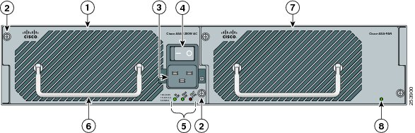
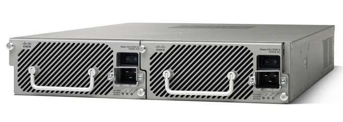
| 1 | Power supply module (corresponds to PS1 indicator) | 2 | Power supply module/fan module removal screws |
|---|---|---|---|
| 3 | Power supply module plug | 4 | On/Off rocker switch for power supply module |
| 5 | Power supply module indicators | 6 | Power supply module or fan module handle |
| 7 | Fan module | 8 | Fan module indicator |
ASA 5585-X Power Supply Module and Fan Module Indicator Lights
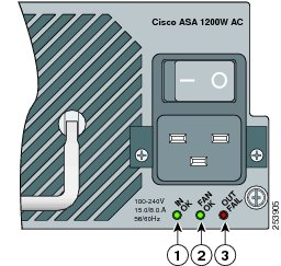
| Indicator | Description | |
|---|---|---|
| 1 | IN OK | Status of power supply module: - Unlit—No AC power cord connected, or AC power switch off. |
- Green—AC power cord connected and AC power switch on.
|
| 2 | FAN OK | Status of fan module:
- Unlit—Fan module failure, or AC power switch off.
- Green—AC power cord connected, AC power switch on, and internal fan is running.
|
| 3 | OUT FAIL |
- Red—Output voltage failure.10
|

若有收获,就点个赞吧
0 人点赞
