Cisco ASA 5506-X 5506W-X 5506H-X with FirePOWER Services
ASA 5506-X 5506W-X 前面板
ASA 550H-X 前面板

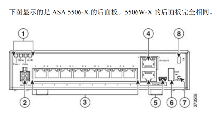
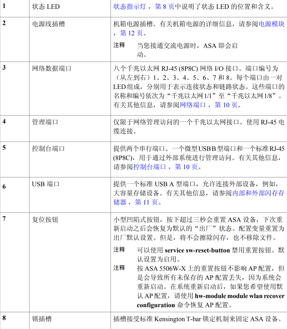
ASA 5506-X 5506W-X 后面板
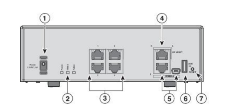
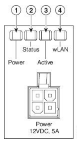
ASA 5506H-X 的后面板

b_install_guide_5508-zh_CN.pdf
Cisco ASA 5508-X with FirePOWER Services
Cisco ASA 5508-X 前面板

| LED | Description |
|---|---|
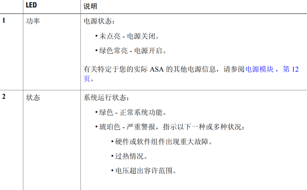
| Power | Power supply status: - Unlit – Power supply off. |
- Solid green – Power supply on.
See Power Supply Modules for additional power information. |
| Status | System operating status:
- Green – Normal system function.
- Amber – Critical alarm indicating one or more of the following:
- Major failure of a hardware or software component.
- Over-temperature condition.
- Power voltage outside the tolerance range.
|
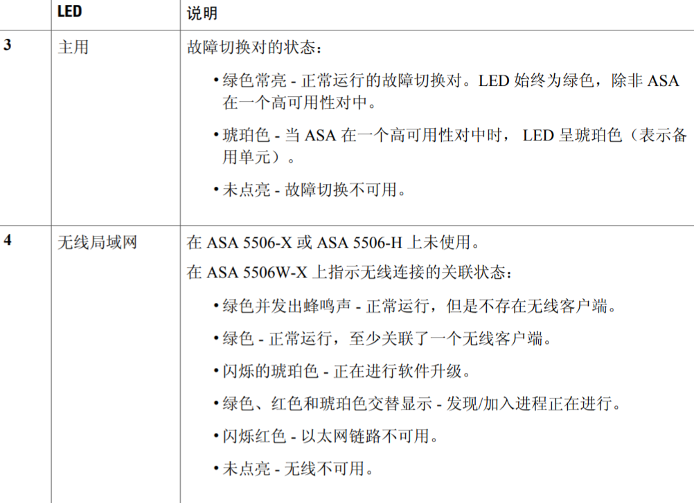
| Active | Status of the failover pair:
- Solid green – Failover pair operating normally.
- Unlit – Failover is not operational.
|
| SSD | SSD LED behavior at first customer ship:
- Unlit – No SSD present.
- Green – SSD installed.
SSD LED behavior after June 2017:
- Unlit – No SSD present or no activity on the SSD.
- Green – Activity on the SSD.
Note
See Replace the SSD for information on replacing a failed SSD.
| | |
| —- | —- |
|

| 1 | Power switch Standard rocker-type power on/off switch. |
2 | Power cord socket The chassis power-supply socket. See Power Supply Modules for more information about the ASA power supply. |
|---|---|---|---|
| 3 | Status LEDs The locations and meanings of the status LEDs are described in LEDs. |
4 | Network data ports Eight Gigabit Ethernet RJ-45 (8P8C) network I/O interfaces. The ports are numbered (from left to right) 1, 2, 3, 4, 5, 6, 7, 8. Each port includes a pair of LEDs, one each for connection status and link status. The ports are named and numbered Gigabit Ethernet 1/1 through Gigabit Ethernet 1/8. SeeNetwork Ports for additional information. |
| 5 | Management port A Gigabit Ethernet interface restricted to network management access only. Connect with an RJ-45 cable. |
6 | Console ports Two serial ports, a mini USB Type B, and a standard RJ-45 (8P8C), are provided for management access via an external system. See Console Ports for additional information. |
| 7 | USB port A standard USB Type A port is provided, allowing attachment of an external device such as mass storage. See Internal and External Flash Storage for additional information. |
8 | Reset button A small recessed button that if pressed for longer than three seconds resets the ASA to its default “as-shipped” state following the next reboot. Configuration variables are reset to factory default. However, the flash is not erased, and no files are removed. Note You can use the service sw-reset-buttonto disable the reset button. The default is enabled. |
| —- | —- |
|
| 9 | SSD LED
Status light for installed solid-state drive (SSD). See LEDsand Solid State Drive for more information. | 10 | SSD bay
Covered slot in which the SSD is installed. You can replace this drive if it fails. See Replace the SSD for more information. |
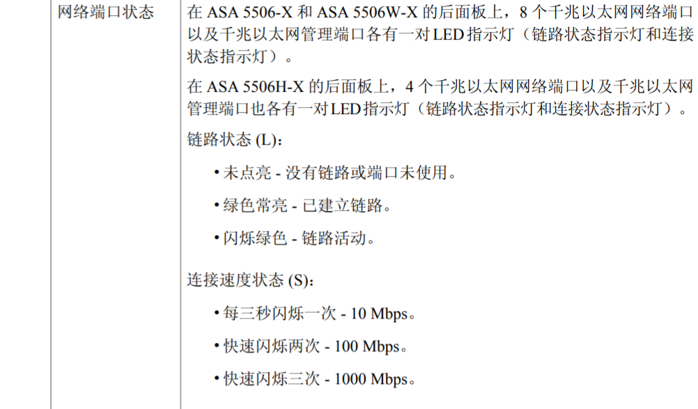
Network Port Status
On the rear panel, a pair of LEDs (Link status and connection Status) for each of the eight Gigabit Ethernet network ports, and the Gigabit Ethernet Management port.Link status (L):
Unlit – No link, or port is not in use.
Solid green – Link established.
Flashing green – Link activity.
Connection-speed status (S):
One blink every three seconds – 10 Mbps.
Two rapid blinks – 100 Mbps.
Three rapid blinks – 1000 Mbps.


