Part I Introduction to a problem
Robots can use a variety of sensors to navigate the environment around them. Let’s take a self-driving car as an example - it has GPS system for outdoor navigation, that helps to determine the location of the vehicle on the world map. It also has cameras, radar and sometimes LIDAR for more precise localization and determining where are the obstacles around the vehicle. In such complex system, data from multitude of sensors is fused together to give an accurate picture of where the robot is, where it is heading and what is around it. 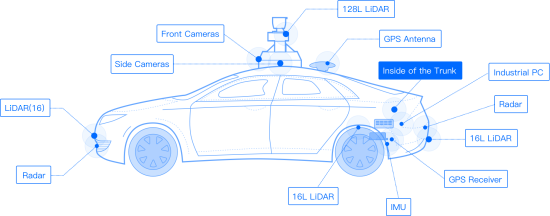
In this lesson we’re going to use Ultrasonic ranger module, which is the most similar to radar in principle of operation with a key difference - it uses ultrasonic sound waves instead of radio waves to measure distance.
Part II Explaining the knowledge
How does Ultrasonic distance sensor work
As we discussed in previous lessons sound is the energy things produce when they vibrate (move back and forth quickly). These vibrations travel through a medium(usually air or water) in waves from the sound (vibration) source.
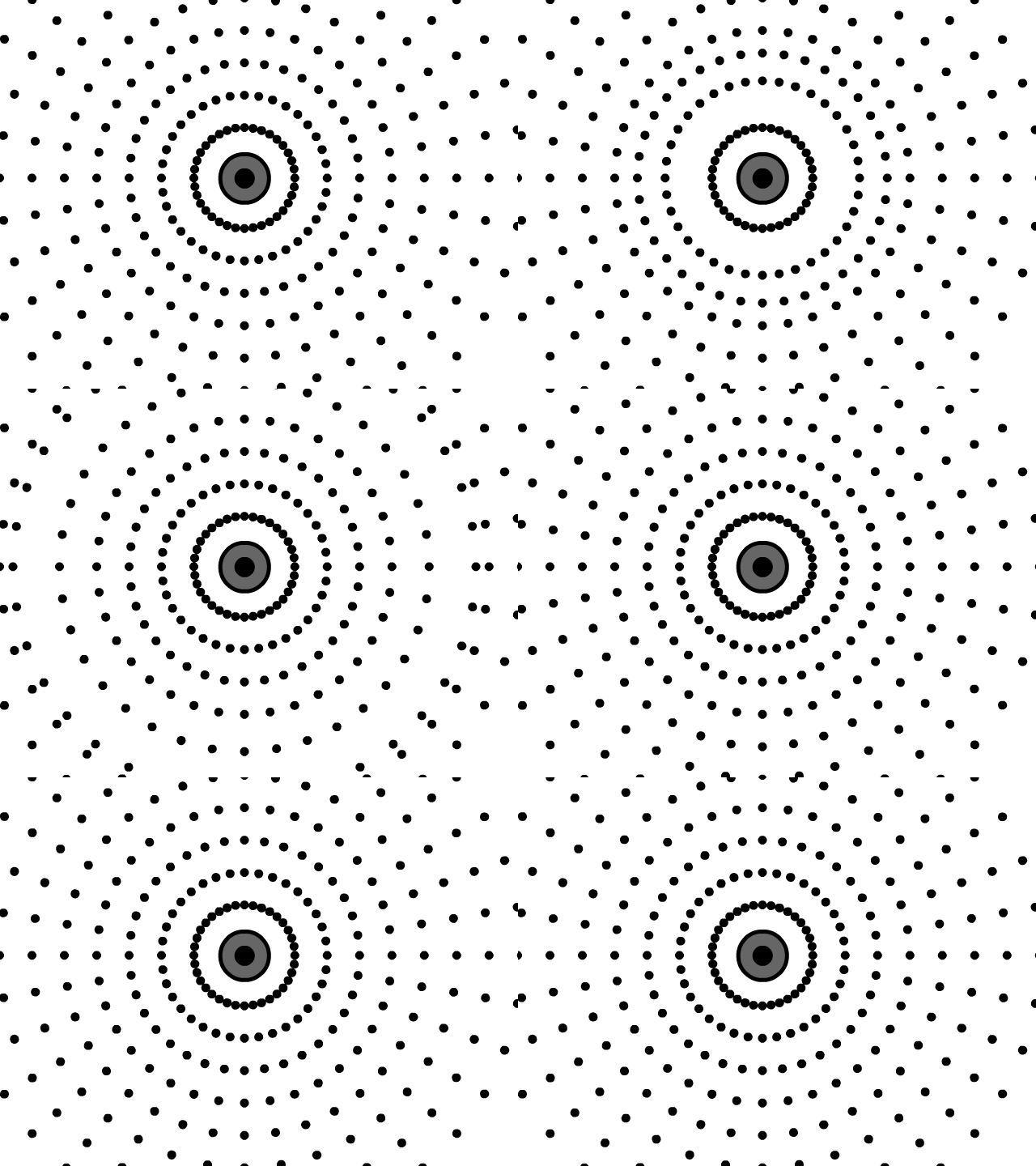
If there is an obstacle in path of sound wave it can deflect the sound waves back, so they would return at the point of origin. Since sound speed in air is known and a constant, 343 metres per second (1,235 km/h) we can use it to calculate the distance between the source of the sound and the obstacle using the following formula:
distance = speed * time
Nature has figured sound can be used for navigation and obstacle-avoidance a long time ago - a good example of nature employing this technique is bats and whales. Both animals are using sound waves to detect and locate obstacles or prey in their environment.
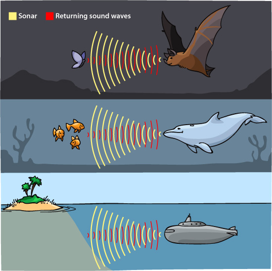
Traditionally used to detect ships under water ultrasonic sensors(also called SONARs, if used for underwater distance measurement) works by transmitting sound waves in pulses. Once those waves hit an object, they return to the sensor, providing data on the speed and location of the object. Ultrasonic sensors able to determine speed and distance, however, they can’t distinguish between different types of objects.
What about LIDARs and radars?
Radars and LIDARs take the idea of “let’s emit something into the environment and watch how much time it takes for it come back” and apply it to other types of waves. Radar stands for RAdio Detection And Ranging and as you might have guessed uses radio waves instead of sound waves. Radio waves have less absorption compared to the sound waves when contacting objects. Thus, they can work over a relatively long distance. The most well-known use of radar technology is for military purposes. Airplanes and battleships are often equipped with radar to measure altitude and detect other transport devices and objects in the vicinity.
LIDAR or LIght Detection And Ranging is a method for measuring distances (ranging) by illuminating the target with laser light and measuring the reflection with a sensor and then measuring the differences in laser return times and wavelengths. LIDARs are generally more expensive, but more precise and with the help of special techniques can be used for creating 3-D representations of the target.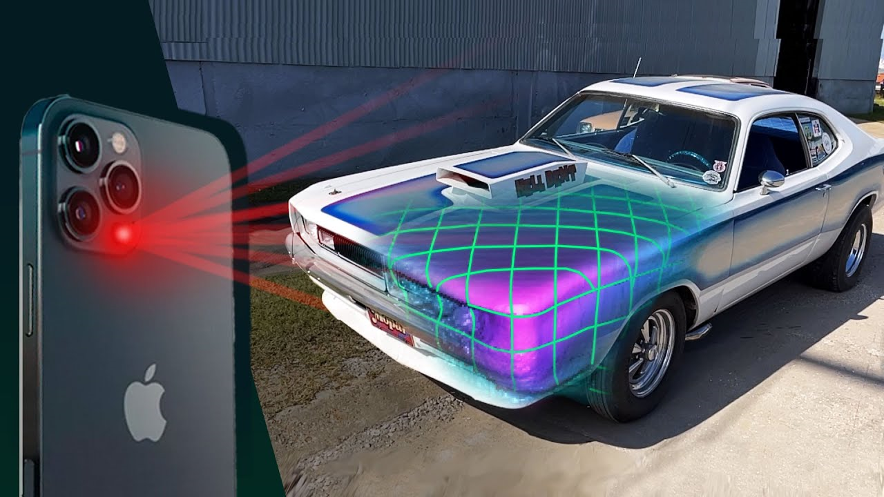
Part III Solving a problem
Task 1: Check the data with Serial monitor
First we want to see what range of measurements we can expect from Ultrasonic ranger sensor - for that we want to output the values received from the sensor on the Serial monitor.  Connect Grove Ultrasonic Sensor to Grove Digital socket D2 and upload the following code:
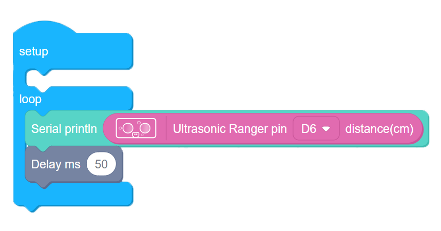
4-1
Note Remember to switch baud rate in Serial monitor to 115200 bps, a default baud rate for BIttle. Baud rate is the speed of data transmission between Bittle’s mainboard and your computer, it is measured in bits per second or bps.
 You will be able to see numbers from 0 to approximately 200 on the Serial monitor - these numbers are distances from Ultrasonic sensor to obstacle in centimeters. If the distance to obstacle is significantly more, for example 400 cm, then Ultrasonic sensor will return 0 as distance, which means the sound wave emitted by sensor has never returned and there is no way to determine the distance to the object.
Task 2: Implement simple obstacle avoidance
For the next task, we’ll need to attach Ultrasonic ranger to Bittle - since the sensor is relatively big it should be installed differently from other smaller sensors. There are two ways to attach Ultrasonic ranger - for this task the second way is preferable.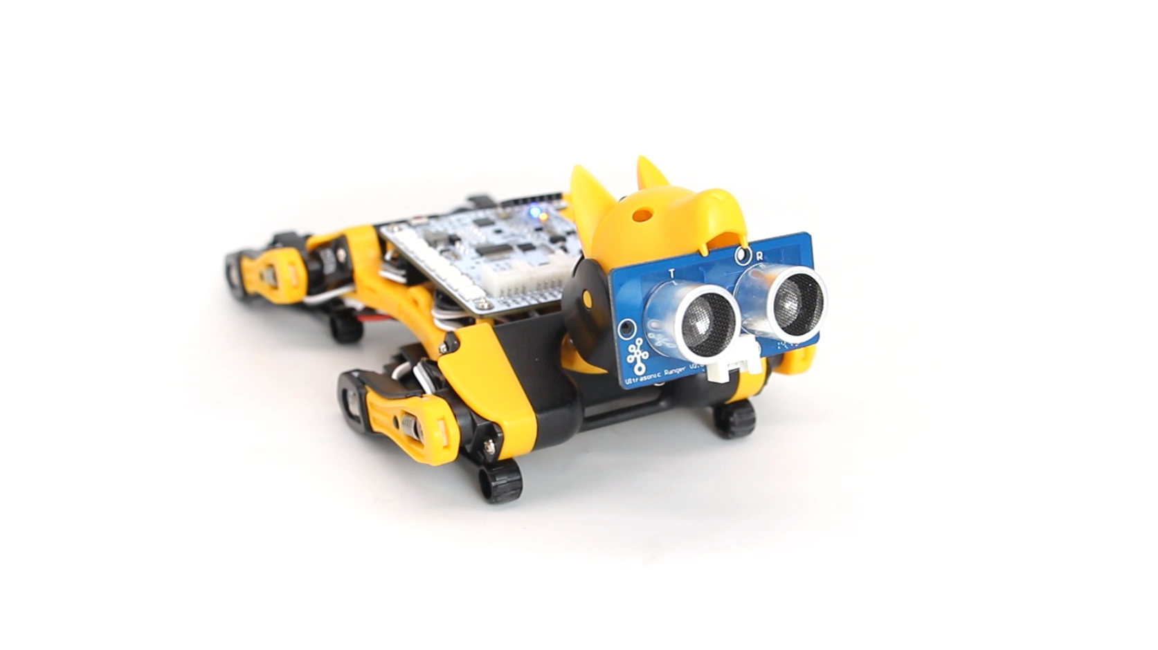
After the sensor is attached to Bittle’s head, we can write a simple code for obstacle avoidance. The logic is simple - Bittle walks forward until obstacle is detected(distance value from US sensor is lower than a certain threshold), then it turns left until the path is clear.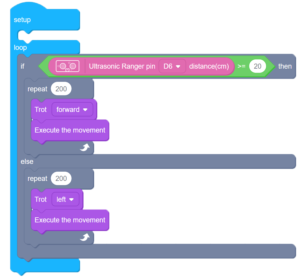
4-2
Since we attached Ultrasonic sensor to BIttle’s head, it’s balance center has shifted toward front and you might notice it’s not as stable as before, especially when turning.
To counteract that you can move the battery a bit towards the back.
Task 3: Make Maze runner program
While the previous program can complete the obstacle avoidance task, we can improve it a bit for navigating more complex environment. Since Bittle’s head is installed on servo, it can turn left and right - we can use that to check which way the path is clear and turn that way, instead of only turning left.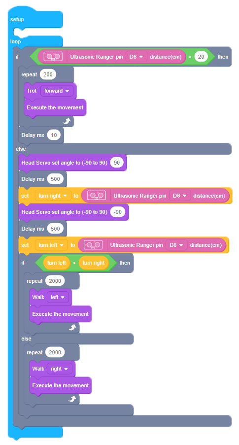
4-3
 We implement that by setting head servo angle to 90 and checking the distance on the right, then setting head servo angle to -90 and checking the distance to an obstacle on the left. After that we can compare the distances and turn in the direction of smaller distance.
Part IV Expanding the knowledge
Write a program changing distance threshold for obstacle avoidance (program two of this lesson) with IR Remote control buttons.

