Introduction to a problem
What would you do if you were walking on a street and then suddenly fell and suffered an injury? Let’s hope that it doesn’t happen yo you, but if it did, you would probably try to attract some attention from the people around you, so they could help you. Our robot can get in trouble too and it needs some form of communication to tell us about it. Bittle is outfitted with Buzzer and seven RGB LEDs we can use for debugging, simple communication and just to make our Bittle more fun to play with!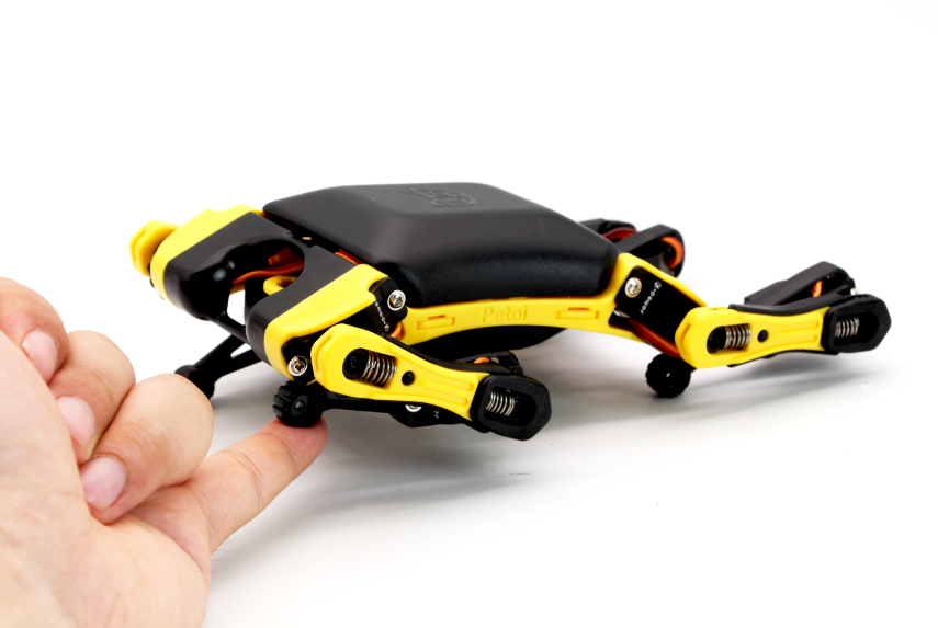
Explaining the knowledge
What is a buzzer and how it works?
The working principle of buzzer, located under Bittle’s mainboard is similar to the working principle of the loudspeaker. It creates the sound wave by rapidly vibrating a surface - in case with loudspeaker the surface is a fabric, plastic, paper, or lightweight metal cone (sometimes called a diaphragm). In case with buzzer the surface is made with piezo material. When an alternating voltage is applied to the piezoceramic element, the element extends and shrinks diametrically. We can control the tone of the buzzer by using PWM - or pulse width modulation. A PWM signal consists of two main components that define its behavior: a duty cycle and a frequency.
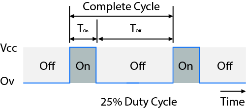
Duty cycle is measured in percentage. The percentage duty cycle specifically describes the percentage of time a digital signal is on over an interval or period of time. The frequency determines how fast the PWM completes a cycle (i.e. 1000 Hz would be 1000 cycles per second), and therefore how fast it switches between high and low states. By cycling a digital signal off and on at a fast enough rate, and with a certain duty cycle, the output will appear to behave like a constant voltage analog signal when providing power to devices.
So, in case with buzzer and speaker, changing duty cycle allows us to control the volume and changing frequency of allows us to emit different notes. Notes are sounds of different frequencies - if you remember from physics lessons sound waves also have frequency.
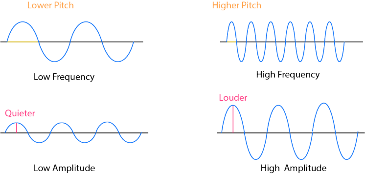
For example note A4 has frequency of 440 Hz, B4 - 493 Hz and so on. The higher pitched sound is, the higher the frequency.
Why RGB LEDs can emit light of different colors?
Well, how do we control the colors of RGB LEDs? Do we also make use of frequencies and PWM? No, the working principle of RGB LEDs is different. In fact, RGB LEDs have 3 tiny LED lights inside them - red, green and blue. By regulating voltage applied to each one of them individually we can emit all the colors of the rainbow. 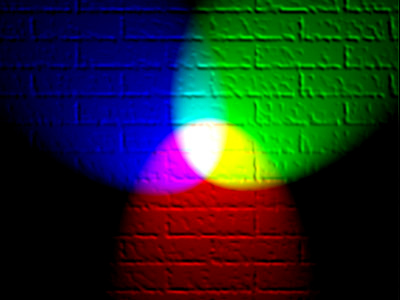
Let’s see how to implement Buzzer and RGB LED control in Codecraft!
Solving a problem
Task 1: Emit sounds with Buzzer
The block for controlling buzzer is located in System category, because it is one of the modules included on BIttle mainboard. To emit sound of note C3 for 1 beat simply make the following code: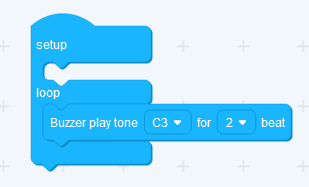
If you wish to make a more complicated melody simply stack more blocks in a sequence - for example here is a sequence for happy birthday tune: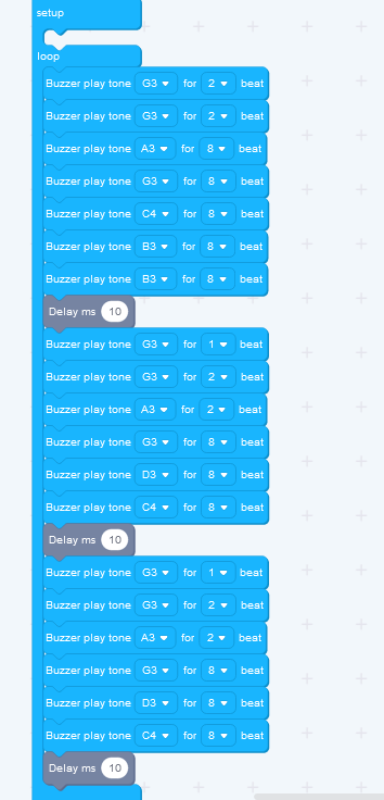

Note Keep in mind however, that each play tone block has a delay for the duration of the beat - so you cannot place it in the movement execution loop, like this:
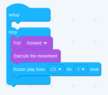
That would cause a one beat delay between each frame of movement. The correct way to do this is:
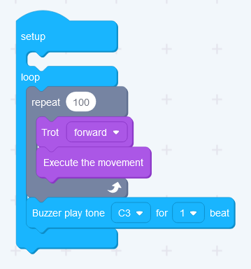
This code will make BIttle Trot while intermittently playing tone C3 for duration of one beat.
Task 2: Control RGB LEDs
We already have used RGB LEDs in Lesson 3.
If the Bittle board is an old board NyBoard V1_0, there are three blocks that control RGB LEDs on Bittle’s mainboard:
set RGB LED number to R G B value
set RGB LED number to color
turn off RGB LED number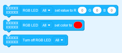
The first block allows us to manually enter number values for Red Green Blue components of color spectrum. The second block opens a color picker, which allows you to tweak Color, Saturation and Brightness parameters. Finally the third block switches RGB LED off.
If the Bittle board is the new NyBoard V1_1, there is a separate block in Codecraft under the “Grove Digital” category to control the RGB LED:
This block allows us to select the Grove interface to control the RGB LED lights, and manually enter the red, green, and blue values of the color spectrum. If conditions permit, you can also purchase Grove - RGB LED Stick (10 - WS2813 Mini) separately, and control the switch or color of different lights through the selection of the last serial number of the block. If you use the matching single RGB LED lamp bead, you can select serial number 1 by default.
Let’s use first block with for loop to make Bittle slowly light up RGB LEDs. 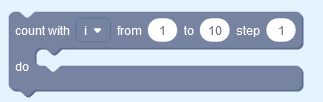
After dragging for loop from Control category, a new variable i will be automatically created and you can drag it from Variables category to Script area.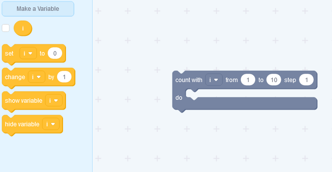
Set R G B values of the LED to i variable, as in screenshot below.
Here is the complete program for the old board NyBoard V1_0: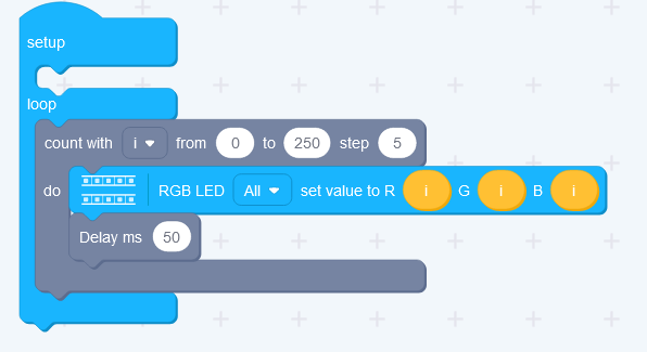
Here is the complete program for the new board NyBoard V1_1: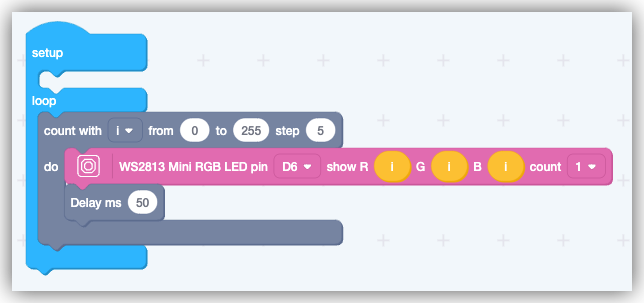 The experimental phenomenon of the old board NyBoard V1_0
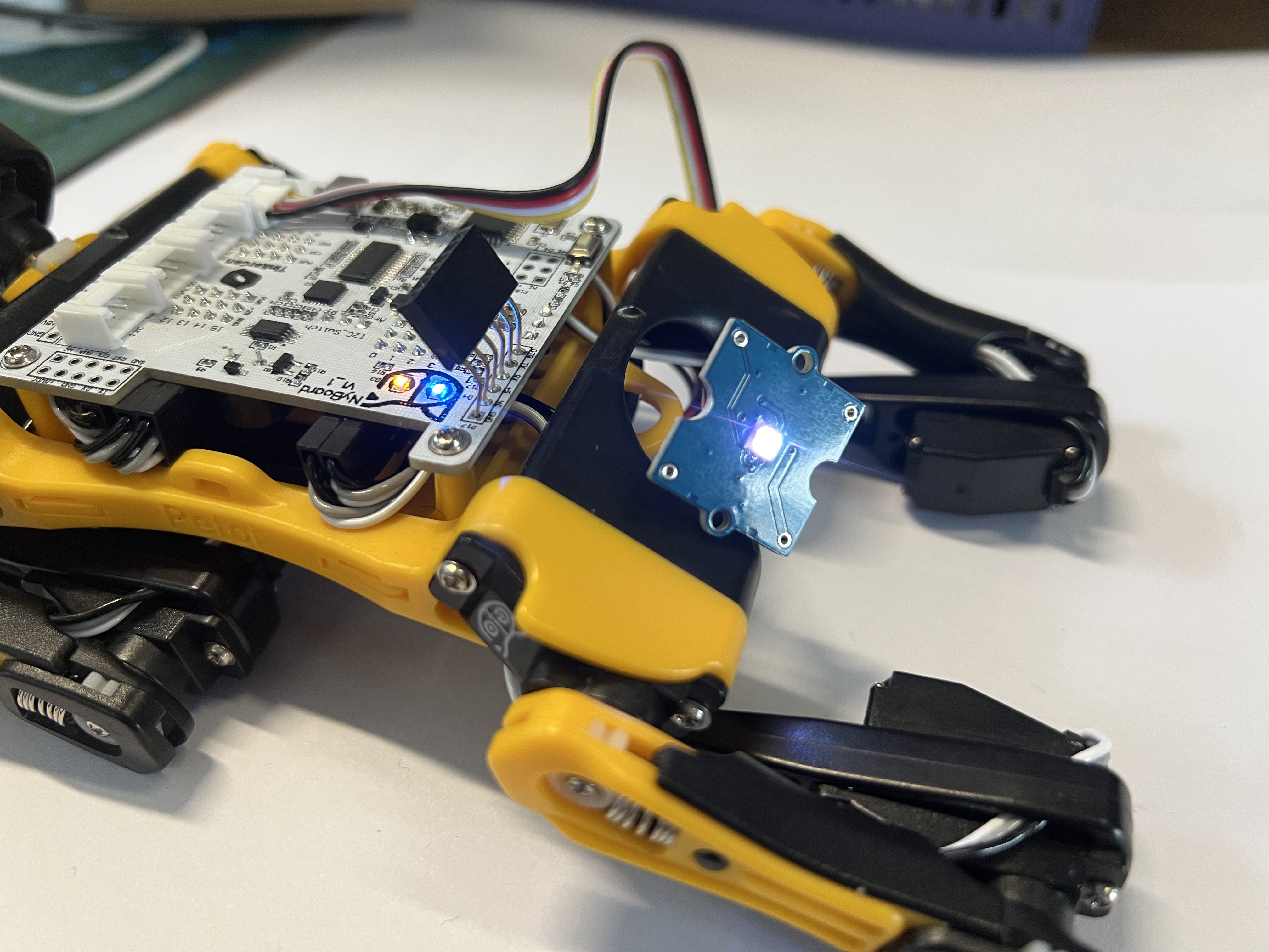
The experimental phenomenon of the old board NyBoard V1_0
Task 3: Make a Christmas Bittle
Let’s combine both sound and light in one program, that will turn Bittle into a Christmas decoration! For that we will use a play melody block, that plays a whole melody instead of individual notes.
Here is the complete program for the old board NyBoard V1_0: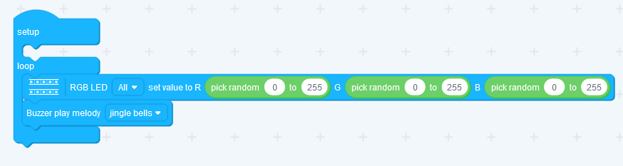
Here is the complete program for the new board NyBoard V1_1: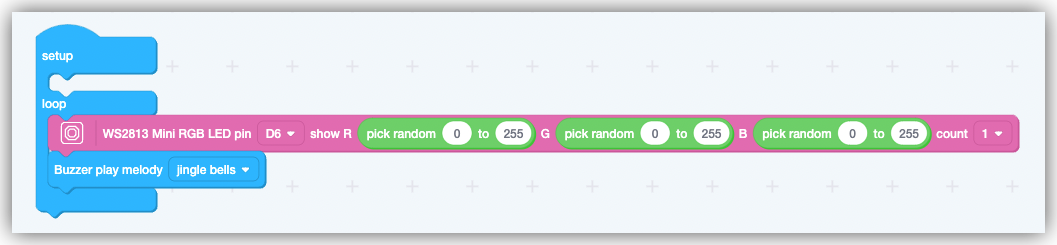
If you have Grove - RGB LED Stick (10 - WS2813 Mini), you can control the color of different LEDs on the new board through the following program.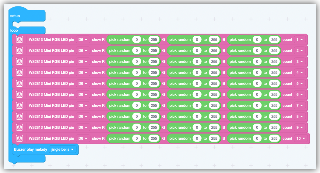
Experimental phenomenon of old board NyBoard V1_0
Experimental phenomenon of the new board NyBoard V1_1(with Grove - RGB LED Stick (10 - WS2813 Mini)):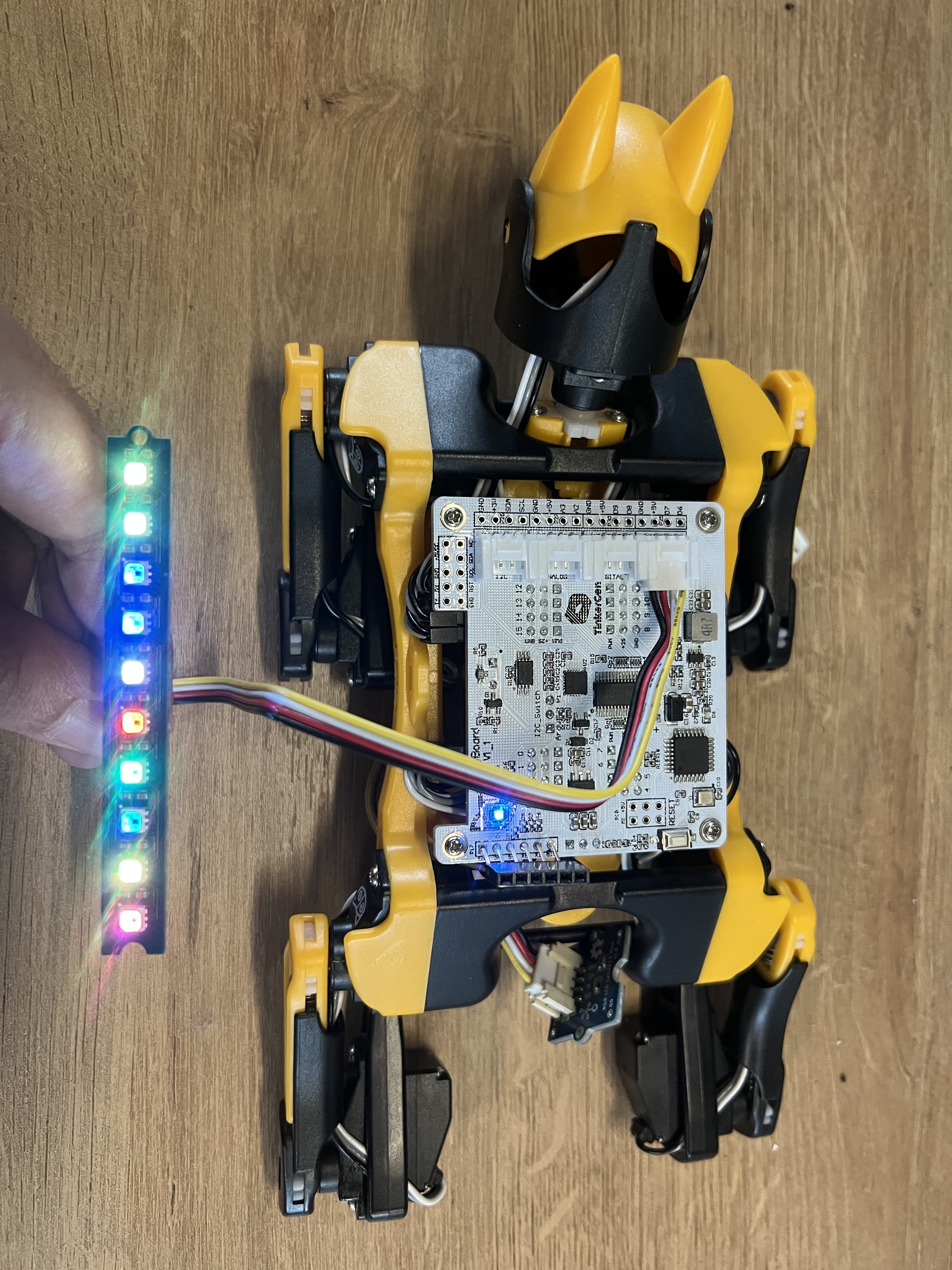
Expanding the knowledge

Or
Change for loop to while loop with variable in this program.
Summarizing the knowledge

若有收获,就点个赞吧
0 人点赞
