CyberPi is an open-source device.
This section provides the open-source materials that can help you obtain the underlying permissions on CyberPi, allowing you to:
- Develop functions for CyberPi
- Design blocks in Extension Builder for CyberPi
- Enable CyberPi to work with third-party hardware
- Develop extension boards and electronic modules for CyberPi
Device schematic diagram
The schematic diagram of a device can help you understand its hardware design.Schematic diagram of Halocode
To understand the hardware design of Halocode, refer to its schematic diagram, as shown in the following figure.
halocode_V1_0.pdf
[For non-Yuque users, click halocode_V1_0.]
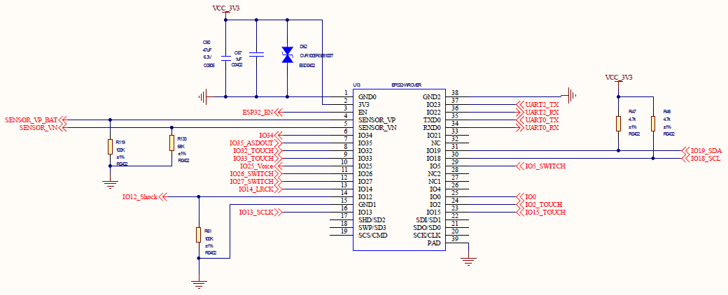
Schematic diagram of CyberPi
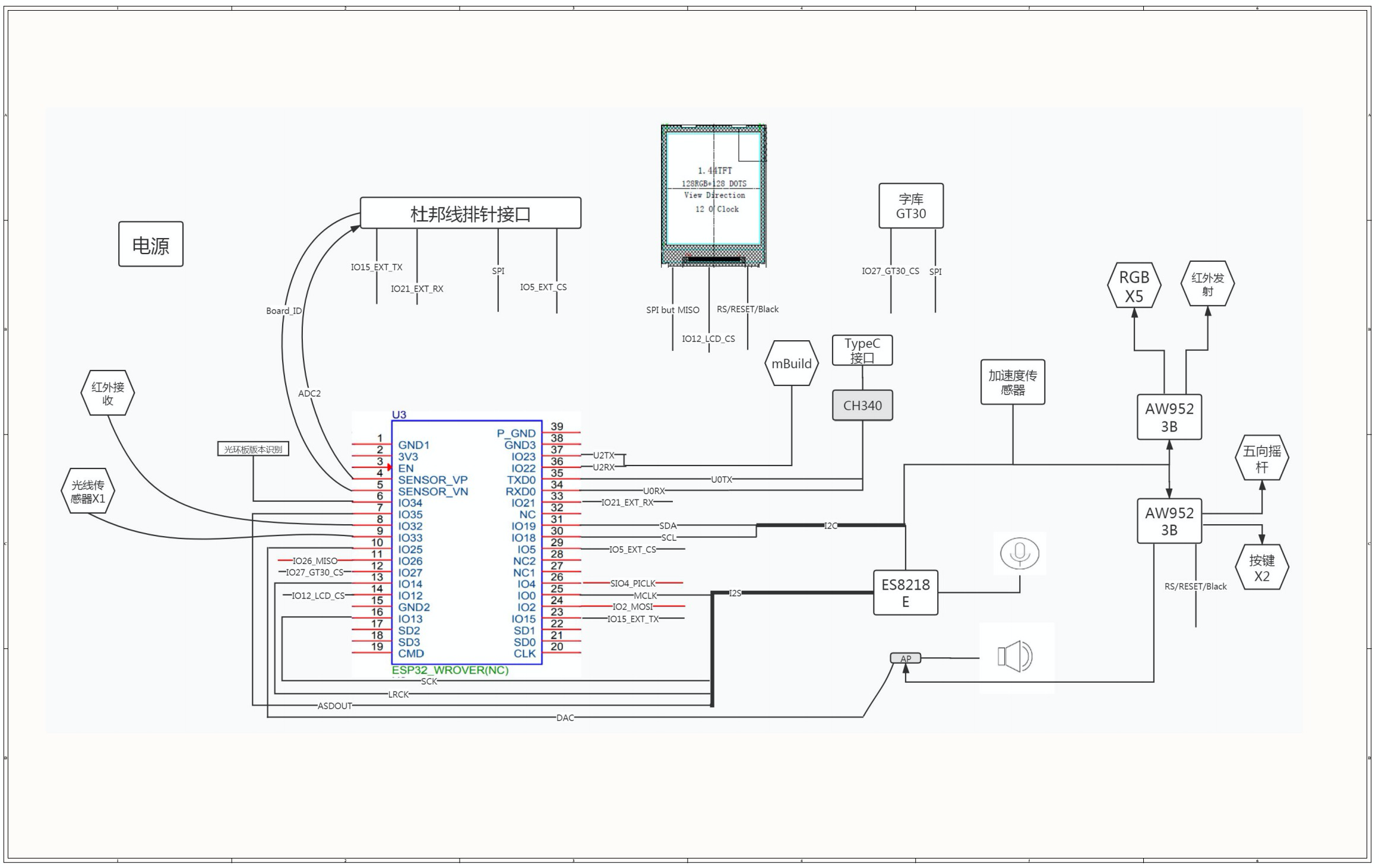 CYBERPI_V1_X (1).pdf [For non-Yuque users, click CYBERPI_V1_X.]
CyberPi_V1_0_PCB.pdf [For non-Yuque users, click CyberPi_V1_0_PCB.]
CyberPi_Gerber.rar [For non-Yuque users, click CyberPi_Gerber.]
Hardware License: License_cern_ohl_p_v2.pdf [For non-Yuque users, click License_cern_ohl_p_v2.]
Software License: GPL v3
Documentation License: CC BY-SA 4.0 International
3D model
If you want to design and print some 3D models to work with CyberPi, refer to the 3D model of CyberPi.
3D model of CyberPi
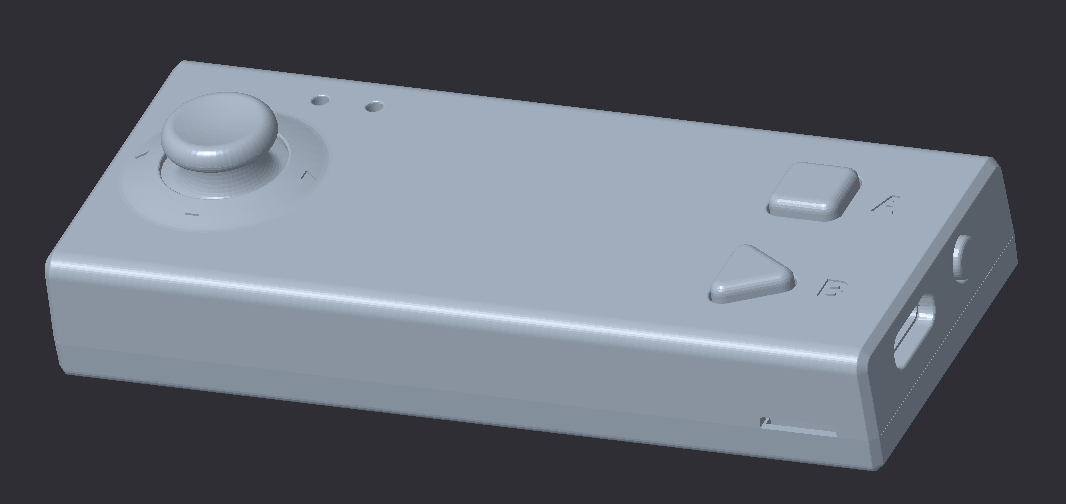
CyberPi.rar [For non-Yuque users, click CyberPi.]
3D model of Pocket Shield
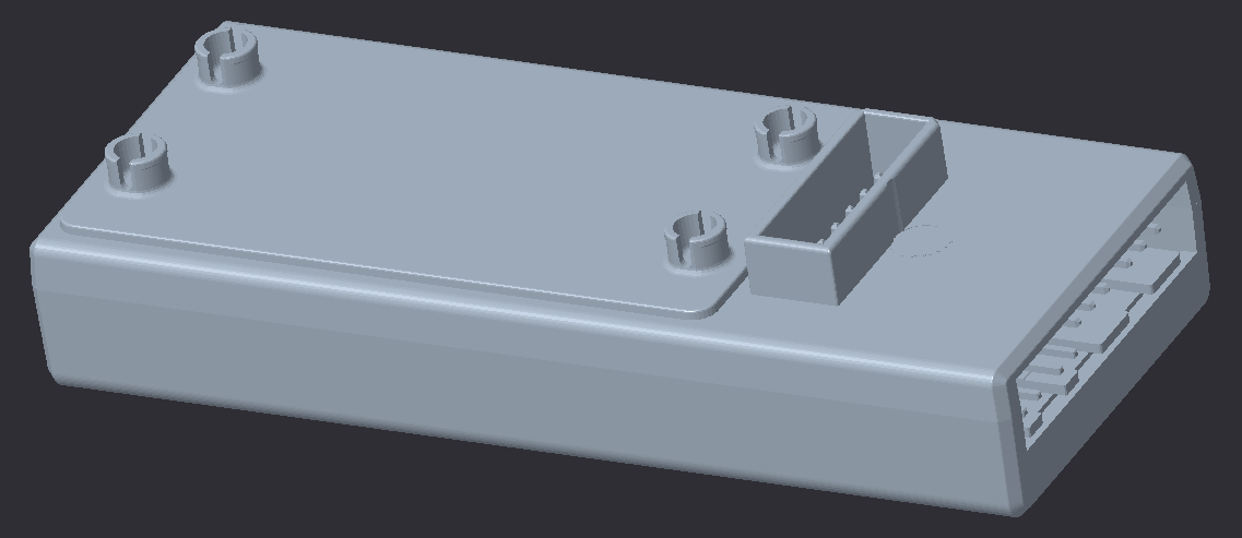
Pocket Shield.rar [For non-Yuque users, click Pocket Shield.]
Third-party compatibility
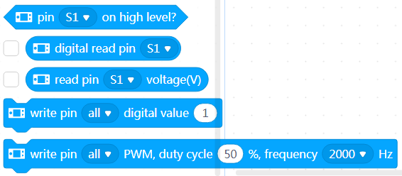
You can use the 3-pin ports on Pocket Shield to connect and control third-party parts or modules, such as Arduino modules.
Related blocks and Python APIs are provided, as described in the following.
Blocks
Python APIs
**cyberpi.pocket.write_digital(val, port)**
Sets the digital input for the specified pin(s)
Parameters:
- val: digital input
- port:
intorstr, port where the pins are located
Setting range: alls1s2S1S212
**cyberpi.pocket.read_digital(port)**
Obtains the digital input for the specified pin
Parameter:
- port:
intorstr, port where the pins are located
Setting range: s1s2S1S212
An int value ranging from 0 to 1 is returned, where 0 indicates a low electrical level and 1 indicates a high electrical level.
**cyberpi.pocket.set_pwm(duty, frequency, port)**
Sets the specified pin(s) to output PWM signals with the specified frequency and duty cycle
Parameters:
- duty:
int, duty cycle of the PWM signals to be output; setting range:0–100, in percentage - frequency:
int, frequency of the PWM signals to be output; setting range:1–2000, in Hz - port:
intorstr, port where the pins are located
Setting range: alls1s2S1S212
**cyberpi.pocket.read_analog(port)**
Obtains the voltage at the specified pin
Parameter:
- port:
intorstr, port where the pins are located
Setting range: s1s2S1S212
A float value ranging from 0 to 5 is returned, in volts.
For more information, see the Pocket Shield Operation Guide.
Extension Builder (recommended)
With the SDK and Python APIs provided by Makeblock, you can design various block extensions to meet your needs.
Designing an extension is not as difficult as you think. Trust yourself! You can be a developer.
Open Extension Builder.
For details about how to use Extension Builder, see the Extension Builder Developer Documentation.
For details about the Python APIs, see the Python API Documentation for CyberPi.
Courses for Extension Builder are on the way. Stay tuned!
SDK for developers
To modify the underlying firmware of CyberPi, you can view the corresponding Gitee project. Note that modifications on the firmware may cause the failure of some functions, but you can update the firmware of CyberPi on mBlock 5 to restore the functions, of course.
With the SDK for developers, you can develop CyberPi in another programming environment other than mBlock 5.
Arduino SDK
Arduino is a platform widely used in the open-source hardware field, and therefore we have designed an open Arduino SDK for CyberPi. You can click the following link to modify the firmware of CyberPi and program it based on the functions it provides by using Arduino.
Visit the Arduino SDK at https://github.com/Makeblock-official/CyberPi-Library-for-Arduino.
Currently, the firmware includes the source code of the drivers for the sensors, display, and LEDs, and available interfaces are encapsulated in the drivers.
Welcome to join us to make it more powerful! We will update this project continuously to develop more features for it.
Arduino examples
Some basic example programs are provided in the following. You can download the official Arduino IDE to update and use the firmware of CyberPi.
1. Button
#include "cyberpi.h"CyberPi cyber;void setup(){Serial.begin(115200);cyber.begin();}void loop(){Serial.print("a:");Serial.print(cyber.get_button_a());Serial.print(" b:");Serial.print(cyber.get_button_b());Serial.print(" menu:");Serial.println(cyber.get_button_menu());delay(500);}
2. Joystick
#include "cyberpi.h"CyberPi cyber;void setup(){Serial.begin(115200);cyber.begin();}void loop(){Serial.print("x:");Serial.print(cyber.get_joystick_x());Serial.print(" y:");Serial.print(cyber.get_joystick_y());Serial.print(" pressed:");Serial.println(cyber.get_joystick_pressed());delay(500);}
3. LED
#include "cyberpi.h"CyberPi cyber;void setup(){cyber.begin();}float j, f, k;void loop(){for(uint8_t t = 0; t < 5; t++){uint8_t red = 32 * (1 + sin(t / 2.0 + j / 4.0) );uint8_t green = 32 * (1 + sin(t / 1.0 + f / 9.0 + 2.1) );uint8_t blue = 32 * (1 + sin(t / 3.0 + k / 14.0 + 4.2) );cyber.set_rgb(t, red, green, blue);}j += random(1, 6) / 6.0;f += random(1, 6) / 6.0;k += random(1, 6) / 6.0;delay(10);}
4. Light sensor
#include "cyberpi.h"CyberPi cyber;void setup(){Serial.begin(115200);cyber.begin();}void loop(){Serial.print("light:");Serial.println(cyber.get_light());delay(500);}
5. Gyroscope
#include "cyberpi.h"CyberPi cyber;void setup(){Serial.begin(115200);cyber.begin();}void loop(){Serial.print("roll:");Serial.print(cyber.get_roll());Serial.print(" pitch:");Serial.println(cyber.get_pitch());delay(25);}
6. Display
#include "cyberpi.h"CyberPi cyber;void setup(){Serial.begin(115200);cyber.begin();for(int y=0;y<128;y++){for(int x=0;x<128;x++){int R = (128-x)*255/128;int G = x*255/128;int B = y*255/128;cyber.set_lcd_pixel(x,y,cyber.swap_color(cyber.color24_to_16((R<<16)+(G<<8)+B)));}}cyber.render_lcd();}void loop(){cyber.set_lcd_light(false);delay(2000);cyber.set_lcd_light(true);delay(2000);}
7. Points
#include "cyberpi.h"CyberPi cyber;#define POINTS_COUNT 200Bitmap points[POINTS_COUNT];float speed_x[POINTS_COUNT];float speed_y[POINTS_COUNT];void setup() {Serial.begin(112500);delay(1000);cyber.begin();for(int i=0;i<POINTS_COUNT;i++){points[i].x = 64;points[i].y = 64;speed_x[i] = random(100)/20.0f-2.5f;speed_y[i] = random(100)/20.0f-2.5f;points[i].width = 1;points[i].height = 1;points[i].buffer = (uint16_t*)cyber.malloc(2);points[i].buffer[0] = 0xffff;}}void loop(){cyber.clean_lcd();for(int i=0;i<POINTS_COUNT;i++){cyber.set_bitmap(points[i].x,points[i].y,&points[i]);points[i].x+=speed_x[i];points[i].y+=speed_y[i];if(points[i].x<0||points[i].y<0||points[i].x>127||points[i].y>127){points[i].x = 64;points[i].y = 64;}}cyber.render_lcd();}
8. Text
#include "cyberpi.h"CyberPi cyber;uint8_t samples[128];int idx = 0;void setup(){Serial.begin(112500);delay(1000);cyber.begin();int font_size = 16;Bitmap *bitmap1 = cyber.create_text(L"你好",0xffff,font_size);cyber.set_bitmap(4,4,bitmap1);Bitmap *bitmap2 = cyber.create_text(L"簡體",0xff00,font_size);cyber.set_bitmap(4,24,bitmap2);Bitmap *bitmap3 = cyber.create_text(L"hello",0x00ff,font_size);cyber.set_bitmap(4,44,bitmap3);Bitmap *bitmap4 = cyber.create_text(L"こんにちは",0x0ff0,font_size);cyber.set_bitmap(4,64,bitmap4);Bitmap *bitmap5 = cyber.create_text(L"여보세요",0x0f0f,font_size);cyber.set_bitmap(4,84,bitmap5);Bitmap *bitmap6 = cyber.create_text(L"Привет",0xf0f0,font_size);cyber.set_bitmap(4,104,bitmap6);cyber.render_lcd();}void loop(){}
9. Loudness detection
#include "cyberpi.h"CyberPi cyber;uint8_t samples[128];int idx = 0;void setup() {Serial.begin(112500);delay(1000);cyber.begin();}void loop(){if(idx<128){samples[idx] = cyber.get_loudness()>>5;idx++;}else{for(int i=0;i<128;i++){samples[i] = samples[i+1];}samples[idx-1] = cyber.get_loudness()>>5;}cyber.clean_lcd();for(int i=0;i<128;i++){if(i==0)cyber.set_lcd_pixel(i,127-samples[i],0xffff);else{int min_level = MIN(samples[i-1],samples[i]);int max_level = MAX(samples[i-1],samples[i]);for(int j=min_level;j<=max_level;j++){cyber.set_lcd_pixel(i,127-j,0xffff);}}}cyber.render_lcd();delay(25);}
10. Microphone data
#include "cyberpi.h"CyberPi cyber;int lo[7] = {48,50,52,53,55,57,59};int mo[7] = {60,62,64,65,67,69,71};int ho[7] = {72,74,76,77,79,81,83};void mic_recv(uint8_t* samples,int len){cyber.clean_lcd();for(int i=0;i<len;i+=8){int current = (int8_t)samples[i+1];if(current>-64&¤t<64){cyber.set_lcd_pixel(i/8,current+64,0xffff);}}cyber.render_lcd();}void setup(){Serial.begin(112500);delay(1000);cyber.begin();cyber.on_microphone_data(mic_recv);for(int i=0;i<14;i++){cyber.set_instrument(i);int idx = 0;while(idx<7){cyber.set_pitch(0,lo[idx],100);delay(600);idx++;}idx = 0;while(idx<7){cyber.set_pitch(0,mo[idx],100);delay(600);idx++;}idx = 0;while(idx<7){cyber.set_pitch(0,ho[idx],100);delay(600);idx++;}}}void loop(){}
11. Music property
#include "cyberpi.h"CyberPi cyber;int lo[7] = {48,50,52,53,55,57,59};int mo[7] = {60,62,64,65,67,69,71};int ho[7] = {72,74,76,77,79,81,83};void data_recv(uint8_t* samples,int len){cyber.clean_lcd();for(int i=0;i<len;i+=16){int current = samples[i+1];cyber.set_lcd_pixel(i/16,current-64,0xffff);}cyber.render_lcd();}void setup(){Serial.begin(112500);delay(1000);cyber.begin();cyber.on_sound_data(data_recv);for(int i=0;i<14;i++){cyber.set_instrument(i);int idx = 0;while(idx<7){cyber.set_pitch(0,lo[idx],100);delay(600);idx++;}idx = 0;while(idx<7){cyber.set_pitch(0,mo[idx],100);delay(600);idx++;}idx = 0;while(idx<7){cyber.set_pitch(0,ho[idx],100);delay(600);idx++;}}}void loop(){}

若有收获,就点个赞吧
0 人点赞
