- How does the Quad RGB sensor react when it detects a line?
- How does the sensor tells a line from a background?
- Let the sensor learn new line and background with the learning button
- Write a simple line following program
- Read the position of the mBot relative to the line from the line following status
- Read the position of the mBot relative to the line from the deviation value
- Apply the concept of Kp
How does the Quad RGB sensor react when it detects a line?
The quad RGB sensor’s four indicators help you quickly know what the sensor have detected - when the background is detected, the indicator lights up; otherwise, the indicator does not light up.
By default, the quad RGB sensor identifies lighter colors as backgrounds and darker colors as lines.
How does the sensor tells a line from a background?
The quad RGB sensor has 4 probes capable of detecting light intensity. They work by actively detecting the intensity of the reflected light after the fill light shines on the object.
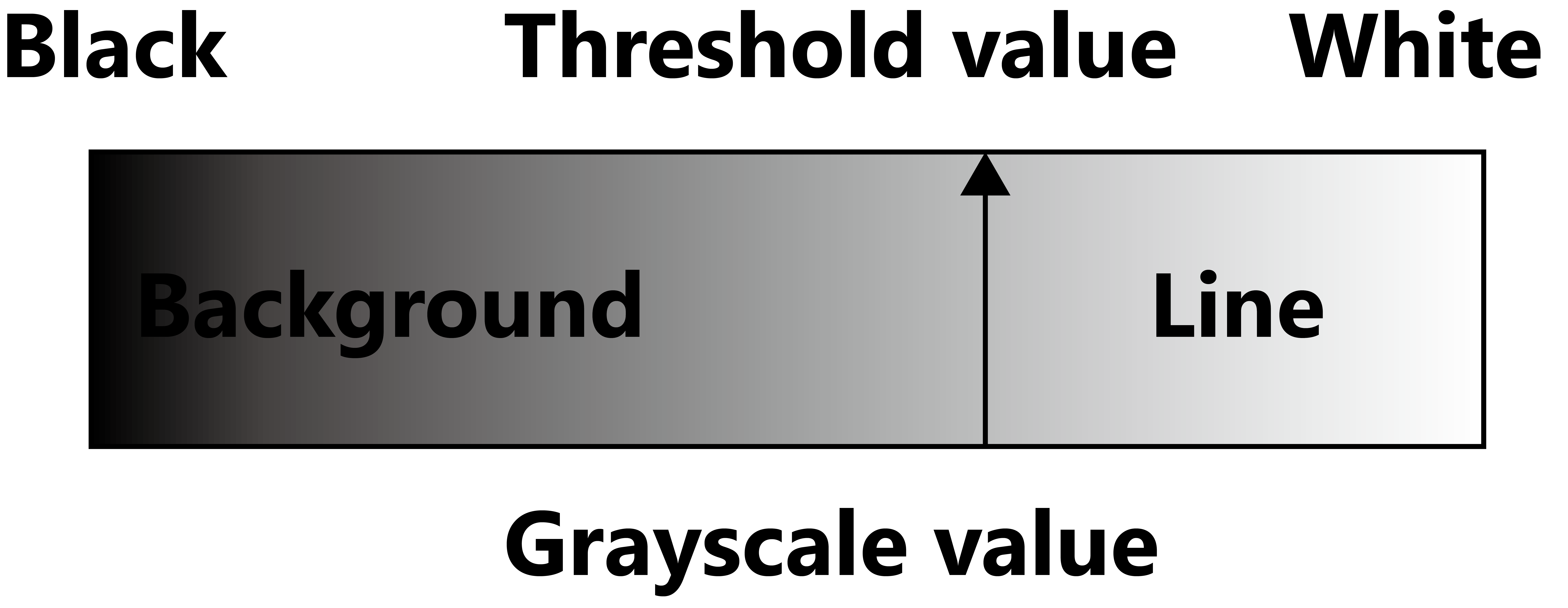
The sensor can infer the grayscale value of the object. The higher the grayscale value, the brighter the object is, otherwise the darker it is.
To distinguish between the line and the background, we also need to give the sensor a threshold value, telling the sensor that the colors above or below this threshold are background colors, otherwise they are lines. In this way, the sensor can distinguish between backgrounds and lines.
By default, we set a uniform threshold value for the quad RGB sensor, so that you can use it out of the box.
Default threshold value
You can also set a new threshold value or define dark colors as backgrounds by learning
Let the sensor learn new line and background with the learning button
In contests, we often use line following maps with white lines on a black background (which makes the map more durable) or other combinations of background and line colors. In these cases, we need to use the calibration function of the quad RGB sensor.
The learning feature enables the quad RGB sensor to find the fill light color and threshold value that best matches the current ambient light, background color, and line color. The methods are as follows.
Double-click: trigger the line following learning.
- Place the two probes of the sensor on the background of the line following map, and double-click the learning button.
- When you see the two line following indicators flashing rapidly, at a fixed height on the background, shake the sensor until the indicators stop flashing rapidly (this will take about 2.5 seconds).
- The learning parameters will be automatically stored. If the learning failed, the two line following indicators will turn to slow flashing and you need to relearn.
Long press: switch the color of the fill light (generally, you don’t need to switch the color of the fill light, it will be set automatically after successful learning)
Write a simple line following program
First let’s look at a simple line following program.
RepeatIf (the head of the mBot is aligned with the line)The mBot goes straight aheadIf (the head of the mBot is on the left side of the line).The mBot turns right at an angleIf (the head of the mBot is on the right side of the line).The mBot turns left at an angle
Note that this program does not yet discuss what to do when the mBot deviates from the line, so let me nest an if-else statement to solve that problem.
RepeatIfIf (the head of the mBot is aligned with the line)The mBot goes straight aheadIf (the head of the mBot is on the left side of the line).The mBot turns right at an angleIf (the head of the mBot is on the right side of the line).The mBot turns left at an angleElseThe mBot stops
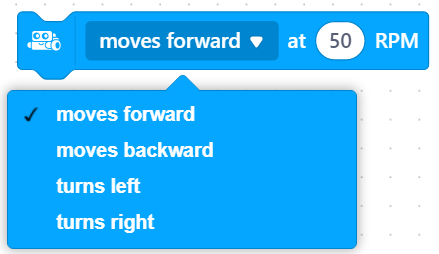
There are also blocks for steering the mBot.
Read the position of the mBot relative to the line from the line following status
With the correct definition of the line and background color, we can better understand the line following status of the quad RGB sensor.
The quad RGB sensor consists of 4-bit binary numbers reading from 0000 to 1111, corresponding to the decimal numbers 0 to 15. The binary numbers, from high to low, correspond to the line and the background results detected by the L2, L1, R1, R2 sensors. When the sensor detects a backgroud color, the corresponding bit reads 1, otherwise, it reads 0. The following is a summary of the reading status and sensor detection results.
| Line following status (Decimal) |
Line following status (Binary) |
L2 status | L1 status | R1 status | R2 status | Illustration (black lines on a white background) |
|---|---|---|---|---|---|---|
| 0 | 0000 | Line | Line | Line | Line |  |
| 1 | 0001 | Line | Line | Line | Background |  |
| 2 | 0010 | Line | Line | Background | Line |  |
| 3 | 0011 | Line | Line | Background | Background |  |
| 4 | 0100 | Line | Background | Line | Line |  |
| 5 | 0101 | Line | Background | Line | Background |  |
| 6 | 0110 | Line | Background | Background | Line |  |
| 7 | 0111 | Line | Background | Background | Background |  |
| 8 | 1000 | Background | Line | Line | Line |  |
| 9 | 1001 | Background | Line | Line | Background |  |
| 10 | 1010 | Background | Line | Background | Line |  |
| 11 | 1011 | Background | Line | Background | Background |  |
| 12 | 1100 | Background | Background | Line | Line |  |
| 13 | 1101 | Background | Background | Line | Background |  |
| 14 | 1110 | Background | Background | Background | Line |  |
| 15 | 1111 | Background | Background | Background | Background |  |
Read the position of the mBot relative to the line from the deviation value
Based on the grayscale value reading of the sensor probes L1 and R1, along with the color definition for the line and the _background _by the sensor, the sensor is able to calculate the deviation of mBot from the center of the line.
- When the sensor is on the left side of the line, the deviation value < 0; in this case, the head of the mBot needs to turn right, and the left wheels of the mBot should accelerate; the right wheels should decelerate.
- When the sensor is on the right side of the line, the deviation value > 0; in this case, the head of the mBot needs to turn left, and the left wheels of the mBot should decelerate; the right wheels should accelerate.
Combining the motor speed setting principle of the mBot chassis, and the forward speed definition of the encoder motor (counterclockwise is forward speed), it can be seen that if the mBot needs to move forward in a straight line with base_speed, the left wheels need to rotate counterclockwise; the right wheels need to rotate clockwise. We can set the speed of the encoder motor as follows:
Left wheel: base_speed, right wheel: -1*base_speed.
Therefore, the deviation value can be used to dynamically increase or decrease the motor speed for smoother line following.
When the sensor is on the left side of the line,
the deviation value < 0; in this case, the head of the mBot needs to turn right,
and the left wheels of the mBot should accelerate; left_speed = base_speed + absolute value deviation value = base_speed - deviation value
the right wheels should decelerate, right_speed = -1(base_speed-absolute value(deviation value))=-1*(base_speed+deviation value)
When the sensor is on the right side of the line,
the deviation value > 0; in this case, the head of the mBot needs to turn left,
and the left wheels of the mBot should decelerate; left_speed = base_speed - absolute value deviation value = base_speed - deviation value
The right wheels should accelerate, right_speed = -1(base_speed+absolute value(deviation value))=-1*(base_speed+deviation value)
To sum up, we can get the formula for setting motor speed during line following.
left_speed = base_speed - offset value
right_speed =-1*(base_speed+offset)
The base_speed is the base speed of the mBot following line, and the deviation value is the mBot’s position in relation to the line as inferred by the line following sensor.
Apply the concept of Kp
Although very crude, with
left_speed=base_speed-deviation value
right_speed =-1*(base_speed+deviation value
a simple closed-loop control is implemented.
The motor RPM controls the movement of the mBot, which changes its position relative to the line.
The position of the mBot is sensed by the quad RGB sensor and caculated as a deviation value, and finally we use the deviation value to set a new motor RPM for the mBot.
However, if we use the above formula directly, we can easily find that the actual results is not satisfactory. We know that we need to turn right when the mBot deviates left, but if it does not turn right or turns too far, it will not be able to achieve a better line following result. We need a parameter to control the effect of the deviation value on the degree of turning. This is where the proportional controller “Kp” comes into play.
In the more complex robot control algorithm, engineers often introduce integrating and differential proportional controlleror to smooth out the entire control process. However, this is much more complex and we will not expand on it here.
With the Kp concept, we can rewrite the original formula as follows
left_speed=base_speed-Kp*deviation value
right_speed =-1(base_speed+Kpdeviation value)
In general, the larger the base_speed, the larger the Kp value will need to be to prevent the mBot from not turning in time, while the smaller the base_speed, the smaller the Kp will need to be to prevent over-turning. There is no fixed Kp setting, but rather you should choose the value for your situation and needs.

若有收获,就点个赞吧
0 人点赞
