Overview
This document is intended for
driver developers. It mainly introduces the standards and operating practices
of LabVIEW plug-and-play drivers, as well as the principles of VI design, instrument
I / O, style, and error reporting. This document also includes descriptions of
instrument driver components and component integration methods. In addition,
this document describes a process for developing a practical instrument driver.
Other resources available to
instrument driver developers include instrument driver templates and instrument
driver guides, which are available from the NI Instrument Driver Network (
ni.com/idnet ).
Before using this document,
you should have a basic understanding of instrument control and be familiar
with the operation of LabVIEW. You should also be familiar with the Virtual
Instrument Software Architecture (VISA) application programming interface
(API).
Directory
1. Instrument Driver Guidelines
2. What is LabVIEW Plug and Play Instrument Driver?
3. LabVIEW Instrument Driver Development
4. MSO5000/7000/8000 Plug and Play Instrument Driver
1.InstrumentDriver Guidelines
1.1 Before You Develop Your Driver
Firsr,familiarize yourself with the instrment, its capabilities, and use. Being familiar with the instrument and its uses in actual applications helps you design a useful instrument driver application programming interface (API). Read the operating manual thoroughly. Learn how to use the instrument manually before you attempt developing interfaces to it. Use the instrument in an actual application to get practical experience. If the operating manual explains how to set up a simple test, do so.Second, familiarize yourself with the instrument programming manual. Study the programming section of the instrument manual. Read the information on the instruction set to familiarize yourself with the available controls and functions and the organization of the features. Determine which instrument features you want to access for programmatic use. Test sending commands to the instrument to understand how the commands affect the operation of the instrument. Use one of the following tools to aid in interactive testing.Communicate with Instrument Utility—(Windows Only) Select the Devices and Interfaces option in Measurement and Automation Explorer (MAX) to communicate with IEEE-488.2 instruments. Use this utility to read, write, and query an instrument in a graphical environment. Use this utility to test instrument commands as you develop instrument drivers.VISA Interactive Control—NI-VISA includes the VISA Interactive Control (VISAIC) utility, which is called on all platforms that support the LabWindows/CVI Run-Time Engine. This utility provides access to all VISA functionality interactively in a graphical environment. Use this utility to test instrument commands as you develop instrument drivers.Instrument I/O Assistant—The Instrument I/O Assistant Express VI, available in the Express»Input or Express»Output palette, lets you send commands to an instrument, then view and parse the responses in real-time using steps. When you place the assistant on the block diagram, the interactive window appears. Though the assistant provides simple instrument control when an instrument driver is unavailable, you can use it as an interactive tool as well.Finally, Use the following settings for the options in the Tools»Options menu in LabVIEW when creating instrument driver VIs:
- Paths: Check Use default.
- (Recommended) Front Panel: Select the Modern 3D style for use for new VIs.
- Block Diagram: Check Use transparent name labels.
- Block Diagram: Uncheck Place front panel terminals as icons.
- Block Diagram: Uncheck Enable automatic error handling in new VIs.
- Block Diagram: Uncheck Enable automatic error handling dialogs.
- Environment: Check Use default colors.
- Environment: Check Use default font.
1.2 Driver Architecture and API Design
Adhere to design guidelines and be consistent when developing the instrument driver API. Doing so ensures consistency within the API itself and with the API for drivers for similar instruments.
Design the instrument driver for use in simple and advanced applications.
Use the VISA I/O library to communicate over the GPIB, VXIbus, Serial, USB, PXI, and Ethernet bus interfaces.
Design VIs that give users the appropriate amount of control of their instruments. Design VIs for reuse as subVIs.
Design an instrument driver that optimizes the programming capability of the instrument.
(Recommended) Design configuration VIs so they do not rely on the status or setting of another VI.
Design VIs to work well with other VIs in the instrument driver.
Minimize redundant parameters.
Design the instrument driver for programmatic use.
Design the instrument driver to work with multiple instruments simultaneously in the same application.
Design the instrument driver to work with multiple instruments simultaneously in the same application.
Group the API VIs into categories by instrument capabilities. You can categorize most instrument driver VIs as Initialize, Close, Configure, Action/Status, Data, or Utility VIs.
Use error in, error out, VISA resource name and VISA resource name out parameters in your VIs to help users control data flow and to force data dependency in their applications.
Include the following VIs in the instrument driver unless the instrument does not support the functionality: Revision Query, Self Test, Reset, and Error Query.
(Recommended) Design the appearance and functional structure of the instrument driver so it is similar to drivers for instruments of the same type.
(Recommended) If the instrument driver supports the serial bus interface, ensure users can access configurable bus settings from the Initialize VI and the default values match the instrument default values.
Optimize driver performance by transferring data using binary transfers.
1.3 VIs:
1.4 Control/Indicators: Naming and Data Representation
1.5 VI Front Panels
1.6 Icon and Connector Panes
1.7 Block Diagrams
1.8 Testing
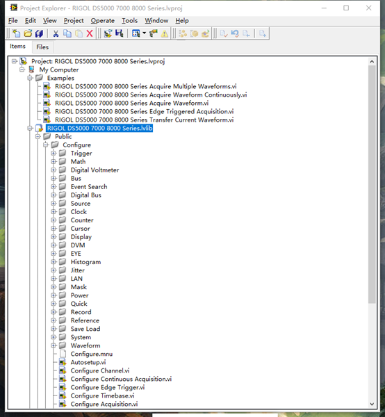
2.LabVIEW Plug-Nnd-Play Instrument-Driven Model
Many programmable
instruments have a large number of functions and modes. Because of its
complexity, it is necessary to provide a unified design model to assist
instrument driver developers and end users who develop instrument control
applications. LabVIEW plug-and-play instrument-driven models include guidelines
for external and internal structures . The external structure shows how the
instrument driver interacts with the user and other software components in the
system. The internal structure shows the internal organization of the
instrument driver software module.
Instrument Driver External Structure
The instrument driver consists of API VIs that
users call from higher-level applications. The figure below shows how the
instrument driver interacts with the rest of the system.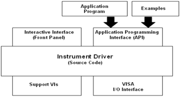
The external
structure shows the interactive interface and programming interface presented
by the instrument driver. An application programming interface (API) is a set
of instrument-driven VIs that users can call for use in end-user systems. For
example, a manufacturer’s test system can make instrument driver calls to
communicate with a multimeter or oscilloscope.
End users can learn
about the API through the instrument driver front panel. By interactively
running the front panel of the instrument driver VI, end users can understand
the impact of each control on the instrument. After understanding the settings,
end users can add instrument driver VIs to the application.
The Virtual
Instrument Software Architecture (VISA) I / O interface is a set of LabVIEW
functions that the driver uses to communicate with the instrument hardware.
VISA is a mature standard instrument interface that can control GPIB, USB,
serial, and other instrument buses. For a description of VISA functions and
controls, refer to the LabVIEW Help .
Support VIs are VIs
that you do not want the end user to access directly. Therefore, supporting VIs
are not part of the instrument driver API. For example, the instrument driver
usually calls the “Default Settings” VI during initialization to set
the instrument state to allow the rest of the instrument driver VI to perform
stable and reliable control of the instrument. Only the Initialize VI and Reset
VI use the Default Settings VI as a subVI, so this VI should be considered a
supporting VI.
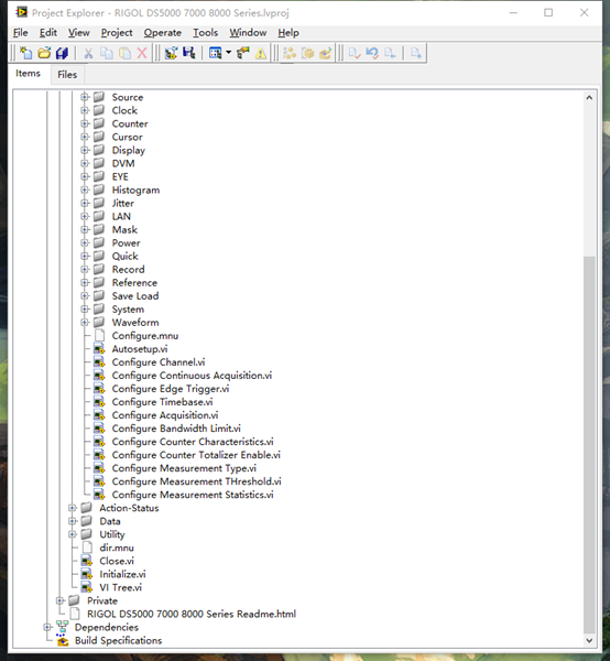
Instrument-Driven Internal Design Model
The instrument-driven internal structure
defines the organizational structure of the instrument-driven VI. All
user-accessible API VIs are organized into a modular hierarchy based on
instrument functions.
The following
figure shows the internal structure of the LabVIEW instrument driver. The end
user has the granularity needed to properly control the instrument in the
application. For example, an end user can initialize all instruments at once,
configure multiple instruments, and trigger multiple instruments at the same
time. In addition, users only need to initialize and configure the instrument once,
and then trigger the instrument multiple times and read data from it.
Instrument Driver API VI
The Instrument Driver API VI can be divided
into the following six types:
Initialization— All LabVIEW instrument drivers must include an
initialization VI. This VI is used to establish communication with the
instrument, so it is the first instrument driver VI to be called. You can also
choose to perform instrument identification query and reset operations through
this VI. This VI can also set the instrument to the default power-on state or
other states.
Configuration-The Configuration VI is a collection of software programs
used to configure the instrument for specific operations. Instrument driver
APIs often include multiple configuration VIs. The number of configuration VIs
in the instrument driver depends on the unique capabilities of the instrument.
After the configuration VI is called, the instrument is ready to perform measurements
or simulate the system.
Action
/ State- Action / State VIs can be
divided into two categories. The Action VI enables the instrument to start or
terminate test and measurement operations. These operations include triggering
a ready or generating a stimulus. Unlike configuration VIs, these VIs do not
change the instrument’s settings, but instead control the instrument to perform
operations based on the current configuration. The Status VI is used to get the
current status of the instrument or the status of the operation to be
performed. Normally, state VIs are created when other functions require them.
Data-The
Data VI is used to transfer data into and out of the instrument. For example,
VIs that read measured values or waveforms and VIs that download waveform or
digital patterns to the source instrument. The specific procedures under this
category depend on the specific instrument.
Tool-The
Tool VI performs a series of auxiliary operations (for example, reset and
self-test) and includes other custom procedures (for example, calibration or
storage and recall of instrument configuration).
Close-The Close VI is used to terminate software and instrument connections.
All LabVIEW instrument drivers should include a shutdown VI.
Each category of VI
(except initialization and VI and shutdown VIs) contains multiple modular VIs.
The focus of instrument driver development is on the initial design and
organization of the instrument driver API VI.
You can download
NI’s template VIs and customize them to perform operations common to all
instruments, such as initialization, shutdown, reset, self-test, and version
query. The template VI contains instructions for modifying specific drivers for
specific instruments. For more information about custom template VIs, refer to
the LabVIEW Instrument Driver Templates chapter.
In addition to the common functions described
above, users can add other VIs to perform instrument-specific operations. The
specific VI developed depends on the unique capabilities of the instrument.
However, if possible, follow the six instrument driver VI categories described
above.
3.LabVIEW Instrument
Driver Development
This section describes the process of developing a LabVIEW Plug-Nnd-Play
Instrument Driver. The ideal LabVIEW instrument driver should enable the end
user to control all functions of the instrument. Since it is not possible to
enumerate the functions required for all different instrument types (such as
multimeters, counters / timers, etc.), this section focuses on the
architectural specifications applicable to all drivers. The following
information helps organize and package drivers in a consistent manner while
enabling instrument-specific features.
Follow the
three-step process below to develop a LabVIEW instrument driver. Step 1. Design
the instrument-driven structure. Step 2. Create a new instrument driver VI
through the Instrument Driver Project Wizard. Step 3. Add developer-defined VIs
and create example VIs.
Step 1: Design the instrument driver structure
The ideal instrument driver should fit the
user’s needs appropriately-neither redundant nor inadequate. No one type of
driver can meet the needs of everyone, but by carefully studying the instrument
and combining the controls into modular VIs, it can meet the needs of most
users.
As the number of
programmable controls in the instrument increases, so does the need for modular
instrument-driven designs. Avoid implementing all functions of the instrument
in a VI. However, you should also avoid instrument-driven designs where each VI
controls only one function. This approach results in hundreds of VIs in an API.
In addition, this approach forces end users to understand the instrument’s
proprietary command sequence and interaction principles. The modular design
simplifies the programming required to control the instrument.
Before creating a single VI, design the overall
structure of the instrument driver. When designing instrument drivers, consider
them from the perspective of the application and end user.
Understanding Instruments is a Key Step in the Design
Process
The following steps
are one way to develop a LabVIEW instrument-driven architecture.
- Familiar with instrument operation. Read the operation manual carefully. Before developing a VI, learn how to use the instrument interactively.
- Use the instrument in an actual test configuration to gain practical experience. The operation manual may explain how to set up a simple test.
- Study the programming part of the manual. Read the instruction set to learn about the controls / functions available and how they are organized. Determine the best features for programming.
- Check the existing instrument drivers to see if there is a driver that controls similar instruments. Generally, instruments of the same series have similar programming instruction sets, which can be modified and used for other instruments.
- Find controls that are grouped together to perform a single task or function to aid in the development of driven structures. Each chapter of the manual usually corresponds to the function grouping of the instrument driver.
Organize Instrument Commands and Develop Structures
strument-driven
organization refers to the hierarchical structure and overall relationships of
instrument-driven composition VIs.There are two types of API VIs in the
instrument driver: API VIs common to all instruments and API VIs that open the
unique capabilities of the instrument. Template instrument driver VIs
(initialization, shutdown, reset, self-test, version query, and error query)
are used to perform common operations. VIs that open unique features of
instruments are defined by instrument driver developers. Some instrument
drivers may define additional categories, such as “routing” or
“scanning” for switching instruments on and off.Group general VIs and
developer-defined VIs into their own categories. A group of VIs that perform
similar operations makes up a category. The most common VI categories include
configuration, actions / status, data, and tools.The following table shows a
sample instrument-driven organization for a simple oscilloscope. The highest
levels of the hierarchy are template VIs (initialization and shutdown) and
typical VI categories.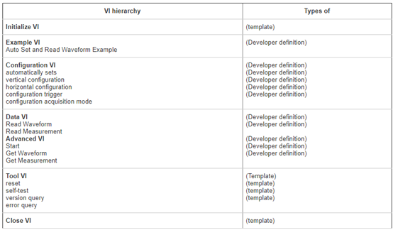
Design Examples
Review the
organizational information contained in most instrument manuals to determine
which parameters to include in the instrument driver VI. It is important to
note that the programming chapters in the manual may divide commands into
different sections, such as configuring measurements, triggering, reading
measurements, and so on. These groups can be used as models to drive the
hierarchy. Find controls that are grouped together to perform a single task or
function to aid in the development of driven structures. The modular driver
contains a single VI in each control group.
The following table
shows the correspondence between simple DMM instrument commands and
developer-defined instrument driver VIs.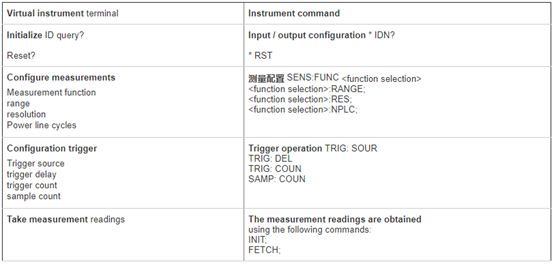
Although instrument
manuals can provide a wealth of information about the structure of the
instrument-driven organization, they should not be relied on entirely.
Instrumentation experience is the main guiding principle. In general, you can
place commands from multiple different command groups into a single VI.
However, sometimes you must separate a set of commands in a manual into two or
more VIs. In the instrument manual, trigger configuration commands are placed
in the same group as trigger ready and execute commands. You can split the
above commands into two VIs—one for configuring triggers and the other for
instrument ready or instrument triggering.
Step 2: Create a new instrument driver using the
Instrument Driver Project Wizard
After the LabVIEW instrument
driver structure design is complete, use the Instrument Driver Project Wizard
to create a new instrument driver, and then modify the newly created instrument
driver VI to work with the instrument.
Using the Instrument Driver Wizard
In LabVIEW 8.x and
later, you can create a new instrument-driven project using the Instrument-Driven
Project Wizard .
Complete the
following steps to create an instrument driver using the Instrument Driver
Wizard:
- From the LabVIEW startup window , select Tools »Instrument» Create Instrument Driver Project to launch the Instrument Driver Project Wizard .
- Select the new template-based driver from the Project Type menu and the instrument type from the Source Driver menu.
- Choose Next .
- Create a driver identifier . The identifier should be realistic.
- Choose Next .
- Select the icon color and type.
- The selection is complete . The project window and LabVIEW Help are displayed .
Step 3: Add Instrument Driver API VI
Add
developer-defined API VIs that define instrument-driven capabilities and use
the instrument’s unique capabilities.
Using the Instrument Driver VI Wizard
The Instrument
Driver VI Wizard creates additional VIs supported by the instrument. If you
create a driver from a class template (such as a DMM template), the instrument
is likely to support additional features not covered by the class template. Use
existing VIs and structures as a guide to create additional VIs for each
supported feature. For example, oscilloscopes often have multiple types of
triggers, but the oscilloscope template only includes support for edge
triggers. If the instrument supports additional trigger types, you should add
this functionality through an additional instrument driver VI.
Complete the
following steps to create an instrument driver using the Instrument Driver
Wizard:
Open the instrument
driver project.
Right-click the
LabVIEW Instrument Driver Project Library (.lvlib) in the Project Explorer
window and select New »Instrument Driver VI from the shortcut menu to display
the Instrument Driver VI Wizard.
On the Start page of the Instrument Driver VI
Wizard , select one of the following options and click the Next button.
- Created through the instrument driver template VI
- to create an instrument driver VI from a template VI.
- Copy from Existing VI —Copy and configure an existing instrument driver VI and its subVIs.
- Configure User VIs —Configure instrument commands, specify response parsing methods, interact with connected instruments, and generate corresponding instrument I / O and string format / parsing code as new instrument driver VIs.
- Add an empty VI -Create an instrument driver VI (contains only VISA resource name input / display controls and error cluster input / display controls).
On the second page of the wizard:
- If you selected Create from an instrument driver template VI on the start page, select a VI from the available instrument driver VI templates on the Copy from template page and click the Next button.
- If you selected Copy from an existing VI on the start page , click the browse button on the Browse VI page to browse, select the VI to add to the project, and click the Next button.
- If you selected Configure User VI on the start page, select Configure VI or Measure VI on the Select VI Type page and click the Next button. Select Configuration VI to create a VI that sends commands to the instrument. Select the Measurement VI to create a VI that sends commands to the instrument and reads responses from the instrument.
- If you selected Add an empty VI on the start page , skip to step 6.
- If you selected Configure User VI in the start page, configure the control settings page and click the Next button. Otherwise, skip to the next step.
Select the appropriate data type for each parameter from the data type drop-down menu.
- In the data type value in the box next to the drop-down menu for setting a default value for each parameter.
- Verify the configured command string in the command preview text box.
- If you selected Configuration VI on the Select VI Type page, select the instrument from the drop-down menu in the Test Command section. If you selected Measurement VI on the Select VI Type page , click the Next button and select the instrument from the drop-down menu in the Test Command section.
- Click the Run Test button to test the configured command. LabVIEW sends the command to the instrument in the command preview text box and displays the number of bytes written to the instrument in the write byte text box. If the command runs successfully, the indicator will turn green. If VISA returns an error, the indicator will turn red. Click the “Explain Error” button to display errors. If you select Measurement VI on the Select VI Type page, LabVIEW reads the instrument response and displays it in the Response text box. You can select the data type of the response in the Configure Response Data Type section.
On the VI
properties page, edit the VI name, path, icon, and description and click the
Next button.
On the summary page, check the information about
the new VI and click the “Finish” button to add the instrument driver
VI and subVIs to the instrument driver project and open the VI. If you create a
VI from a template VI or an existing VI, LabVIEW renames the subVI with the same
name as the existing VI in the project library, but with a different connector
board. LabVIEW does not copy subVIs with the same name and the same connector
board as existing VIs in the project library. The new VI replaces subVIs that
LabVIEW does not add with existing VIs in the project library.
4.MSO5000/7000/8000 Plug and PlayInstrument Driver

若有收获,就点个赞吧
0 人点赞
