最近在做车站信号布置图的任务,由于GDI始终学不会,且有些复杂,我想到了利用Visio这个软件接口
首先先制作一些模具
这是我制作好的模具形状信号机,应答机,下行方向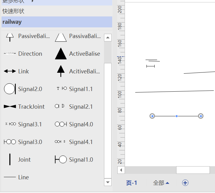
步骤如下
一.下载Visio&打开Visio&制作模具
更多形状—新建模具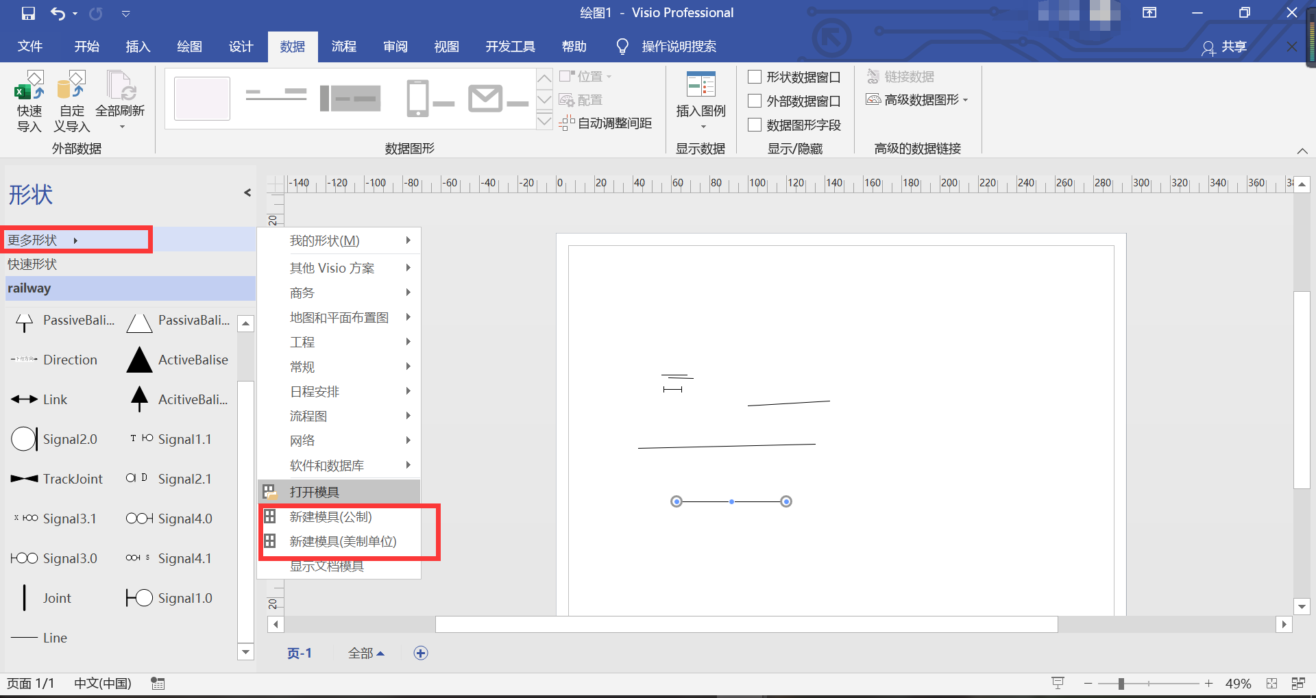
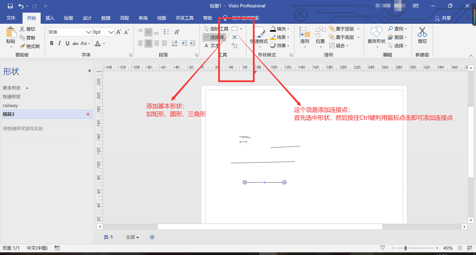
比如由于我的绝缘节之后要来连接轨道区段,所以我在中间添加了一个连接点,并且这个连接点在下一篇起了作用
二、制作好模具之后,可以在形状窗口继续更改Shape的名字
其实Visio中分好多接口
Visio本身作为Application,打开的是Window,和Document,首页是Page,模具是Master,想在Master即我这个模具文件—-vssx/vss文件中找到某个名字的Shape则用Masters[string shapeName];
三.我的站场图模具
语雀上传不了Visio文件
网盘:
链接:https://pan.baidu.com/s/19f29xGDI1G_gUC3Ecz2bSA
提取码:rld5
四、上一篇中说了怎么引用AxDrawingControl至winform窗体也讲了怎么初始设置
1.设置动态连接线从直角变为直线
//设置连接线为直线而不是直角int index=visApp.BeginUndoScope("页面设置");visApp.ActivePage.Background = Convert.ToInt16(false);visApp.ActivePage.BackPage = "";visApp.ActivePage.PageSheet.get_CellsSRC((short)VisSectionIndices.visSectionObject, (short)VisRowIndices.visRowPageLayout,9).FormulaForceU = "2";visApp.EndUndoScope(index, true);
这里的visApp是我定义了一个全局变量
注意引用
using Microsoft.Office.Interop.Visio;
public Application visApp;
在初始AxDrawingControl中写了初始化,同时设置不显示搜索框,但是仍然解决不了我的闪烁问题,还需要继续解决
//设置application不显示搜索框
visApp = this.axDrawingControl1.Document.Application;
visApp.Settings.ShowShapeSearchPane = false;
2.上载模具,添加了在页面点击添加形状的功能—-其实挺鸡肋的,如果不闪烁的话完全可以使用形状窗口拖动操作就好了
currentStencil = visApp.Documents.OpenEx(shapefile, (short)Visio.VisOpenSaveArgs.visOpenDocked);string s = shapefile.Substring(shapefile.LastIndexOf("\\") + 1);s = s.Split(new char[] { '.' })[0];//文件的FileName((DevExpress.XtraEditors.Repository.RepositoryItemComboBox)cbMasters.Edit).NullText = s;SetMasters(currentStencil.Masters);//主要是给ComboBox中添加Item
private void SetMasters(Masters masters){((DevExpress.XtraEditors.Repository.RepositoryItemComboBox)cbMasters.Edit).Items.Clear();foreach (Master master in masters){string s = master.Name;((DevExpress.XtraEditors.Repository.RepositoryItemComboBox)cbMasters.Edit).Items.Add(s);}}
然后在AxDrawingControl中的MouseDown中写了—-很鸡肋是不是蛤蛤蛤
private void axDrawingControl1_MouseDownEvent(object sender, AxMicrosoft.Office.Interop.VisOcx.EVisOcx_MouseDownEvent e){try{if (IsVisioEditable){if (cbMasters.EditValue != null){string s = string.Format("x:{0},y:{1}", e.x, e.y);string shapename = cbMasters.EditValue.ToString().Trim();if (!string.IsNullOrEmpty(shapename)){Visio.Shape shape = axDrawingControl1.Document.Pages[1].Drop(currentStencil.Masters[shapename], e.x, e.y);}}}}catch(Exception ex){WriteLog(ex.Message);}}
3.添加任意的图形
基本上用的是这句
Visio.Shape shape = axDrawingControl1.Document.Pages[1].Drop(currentStencil.Masters[shapename], e.x, e.y);
4.重点来了:怎么连接两个图形
我在这里先举一个连接两个绝缘节的例子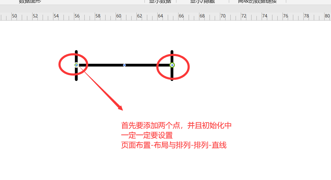
private void ConnectedShapes(Shape BeginShape,Shape EndShape){Visio.Cell BeginXCell;Visio.Cell EndXCell;//用来确定连接线连在图形的上下左右,不同图形值不一样Page visPage = axDrawingControl1.Document.Pages[1];Shape connector = visPage.Drop(visApp.ConnectorToolDataObject, 1.2386, 3.2458);BeginXCell = connector.get_CellsU("BeginX");EndXCell = BeginShape.get_CellsSRC(7, 0, 0);BeginXCell.GlueTo(EndXCell);BeginXCell = connector.get_CellsU("EndX");EndXCell = EndShape.get_CellsSRC(7, 0, 0);BeginXCell.GlueTo(EndXCell);}
关于CellsSRC为什么设置7,0,0
我是利用Visio中的宏录制看到的
宏录制—-在开发工具-录制宏——进行你的操作—-暂停录制—宏—编辑,看到的具体VB代码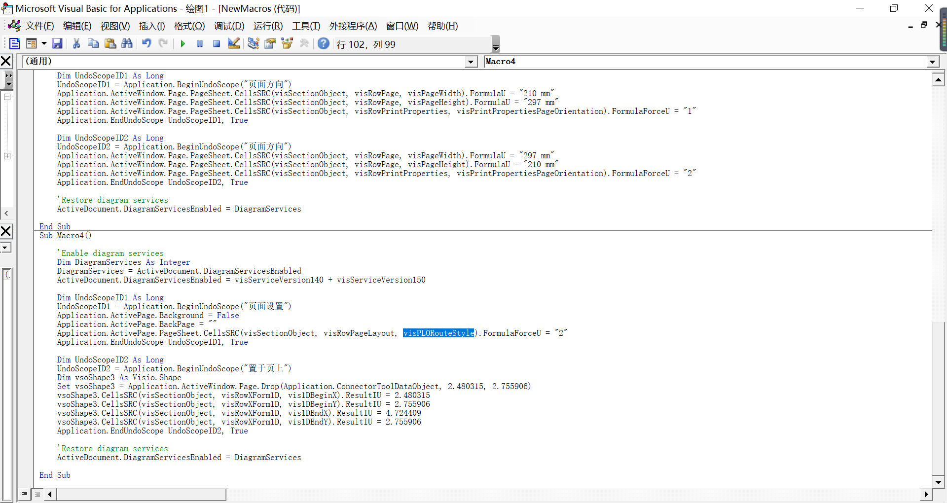
第一步中的设置连接线为直线的只要代码,本来Page.PageSheet.CellsSRC(short Section,short Row,short Column )中的Column需要找到visPLORouteStyle在枚举中并不能找到,
最后查阅了Microsoft的开发书??开发文档还是什么
网址:这个网址是所有枚举的值—-最后好不容易找到了visPLORouteStyle是9,尝试了一下果然成功
https://docs.microsoft.com/zh-cn/office/vba/api/visio.viscellindices
所以巧用宏对于Visio二次开发还是很有用滴
如果不设置直角为直线,根本练不成正常的轨道模样,如果不给绝缘节添加点,会出现“操作对象不正确”这样的提示
还没有连接上道岔,并且这个基础图的设备信息其实是有点问题的—-待解决,不过能画出来已经很好了
还有的一个问题是比例尺的问题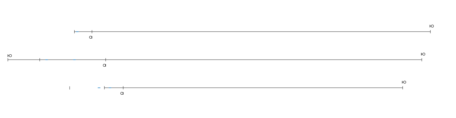

若有收获,就点个赞吧
0 人点赞
