- CAN Protocol Tutorial
- History Of CAN Protocol
- Introduction to CAN Protocol
- Application Of CAN Protocol
- What is CAN Protocol?
- Features of CAN protocol
- Information Routing In CAN Protocol
- System Flexibility In CAN Protocol
- Message Routing In CAN Protocol
- Multicast In CAN Protocol
- Data Consistency In CAN Protocol
- Bit-Rate In CAN Protocol
- Priorities In CAN Protocol
- Remote Data Request In CAN Protocol
- Multi-Master In CAN Protocol
- Arbitration In CAN Protocol
- Data Integrity In CAN Protocol
- Error Detection In CAN Protocol
- Error Detection Performance:
- Error Signalling And Recovery Time In CAN Protocol
- Why CAN Protocol?
- What are the types of CAN Protocol?
- ISO Layer Used In CAN protocol
- What are the Types of CAN Protocol Frames
- Data Frame Format In CAN Protocol
- CAN Protocol Frame Field Explanation
- Extended or 29-bit CAN Protocol Frame Format
- CAN Protocol Remote Frame Format
- CAN Protocol Error Frame Format
- CAN Protocol Overload Frame Format
- Inter-Frame Space In CAN Protocol
- CAN Protocol Working Principle
- How CAN Communication Works?
- Operation Of The CAN Network
CAN Protocol Tutorial
This CAN Protocol Tutorial gives you an overview of the ISO 11898-1 and ISO 11898-2 standards. This will provide you a great introduction to the fundamentals of CAN protocol as to how it is used in automotive design, industrial automation controls, Aerospace design, and many more applications. After that obviously, we will go deep to understand the real networking protocol as to how come it is possible to connect so many ECU in a vehicle.
Even if you have any questions you can also comment below to which the team will reply with a great quality answer and I don’t think so you will get these answers easily from google. Though you are designing any project which is based on CAN or working in any company where you need any support you can contact us at any time. Let’s go start instead of wasting time.
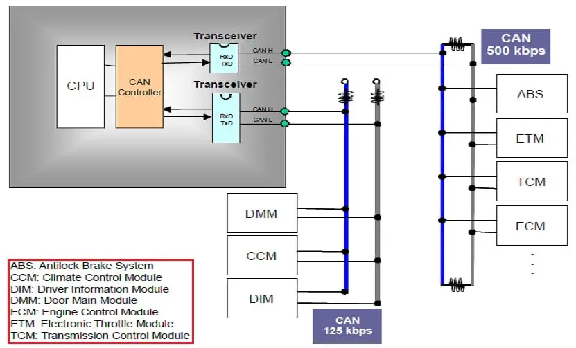
You can see in this figure how the can protocol is being used in a vehicle to make it sophisticated, flexible, and safe with automation control for a human. There are two CAN network with High and Low-speed baud rates. Again there is another ECU that connects two different data rate networks communicating with each other through Gateway ECU.
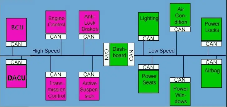
CAN network used in Vehicle
History Of CAN Protocol
- In 1985 Bosch originally developed CAN, a high-integrity serial bus system for networking intelligent devices, to replace automotive point-to-point wiring systems.
- As vehicle electronics became pervasive, complex wire harnesses that were heavy, expensive, and bulky were replaced with CAN throughout the automotive industry.
- In 1993 CAN became the international standard known as ISO 11898.
- Since 1994, several widely used higher-level protocols have been standardized on top of CAN, such as CAN-open* and Device-Net.
- In 1996 the On-Board Diagnostics OBD-II standard which incorporates CAN becomes mandatory for all cars and light trucks sold in the United States.
- Today markets including surface transportation, industrial automation, maritime, and avionics systems have widely adopted CAN.
- Today CAN is incorporated into many micro-controllers (our Embedded has two CAN ports).
Introduction to CAN Protocol
At first electronic devices/ nodes/ECU’s were connected in vehicles via point-to-point wiring systems. The Automotive Manufacturers (OEM) started using more and more ECU’s in-vehicle, which resulted in bulky wire harnesses that were heavier and expensive too which increases the cost of the vehicle. Then the ROBOT BOSCH introduced a specialized internal communication network called the vehicle bus that interconnects electronic devices inside the vehicle.
The Vehicle bus reduced the wiring cost, weight, and complexity, etc. Now there are several types of network types and protocols used in vehicles by various manufacturers for the interconnection of ECU in a network. The most common vehicle bus protocols are the CAN, LIN, VAN, IEBUS, FlexRay, MOST, DC-BUS, J1850, ISO 9141-1/-2, D2B-Domestic Digital Bus.
Among them the various bus protocols are available in the Automotive Industry, the CAN emerged as the standard in-vehicle network due to its energetic features for safety and it became the international standard known as ISO-11898. Bosch has originally developed the Controlled Area Network (CAN) and it has been adopted by the automotive industry.
There are several higher-level protocols that have been standardized on CAN such as CANopen and DeviceNet which are commonly used for industrial communications. CAN is also adopted specifically for the classes of vehicles such as J1939 for commercial vehicles and ISO-11783 for agricultural vehicles.
Application Of CAN Protocol
The main advantages of the CAN as a serial bus lie in the reduction of expensive wiring, as well as an increased performance by enabling a distributed processing system. CAN has been used in the following applications as still now also it is increasing in different applications:
- Passenger Cars.
- Building Automation.
- Trucks and Buses.
- Industrial Machine Control.
- Lifts and Escalators.
- Trains.
- Maritime Electronic Systems.
- Aircraft & Aerospace Electronics.
- Medical Instruments etc.
What is CAN Protocol?
The CAN is a multi-master, broadcasting, multi-casting, message-based, Event-driven, Flexibility, half-duplex, asynchronous type serial networking protocol. It was designed by Robert BOSCH to use it in Automotive vehicles for improving the vehicle networking feature with long-distance communication.
Features of CAN protocol
There are different can feature those are making the CAN unique from other protocol for which it is used in most of the places are:
- Information routing.
- System flexibility.
- Message routing.
- Multicast.
- Data consistency.
- Bit-rate.
- Priorities.
- Remote data requests.
- Multi-master.
- Arbitration.
- Data integrity.
- Error detection.
- Error Detection performance.
- Error signaling and recovery time.
- Fault confinement.
- Connection.
- Single-channel.
- Bus values.
- Acknowledgment.
- Sleep mode/wake-up.
Information Routing In CAN Protocol
In CAN network systems, a node does not make use of the system configuration means of the node address.
System Flexibility In CAN Protocol
If you want to add a new node/ECU in the old available CAN network, then you can add without the change in software or hardware of any node in the network.
Message Routing In CAN Protocol
In CAN, every message is identified by the special unique identifier which does not indicate the destination of the message but only describes the meaning of the data available in the message. So that all the nodes are connected in the network are able to decide by message filtering technology using this message ID either to receive the data or not.
Multicast In CAN Protocol
The multicast means the nodes/ECU’s are connected in the network might be any number of nodes can be simultaneously able to receive the same transmitted message.
Data Consistency In CAN Protocol
The data consistency means in a CAN network it is guaranteed that a message is accepted simultaneously either by all nodes or by no nodes. So that the data consistency is a property of a system achieved by the concepts of multicast and the error handling concepts.
Bit-Rate In CAN Protocol
The speed of the CAN may be different for different networks available in a system. However, in a given network the bit rate is uniform and fixed for all the nodes.
Priorities In CAN Protocol
The message identifier defines a static message priority during the bus access in a CAN network. Mostly each message is having a unique Identifier integer value and it is represented in a hexadecimal number system for increasing the reading and programming flexibility for a developer. The OEM should select the message or his ID as to how much priority it is. The highest is the priority, the lowest is the value of that message.
Remote Data Request In CAN Protocol
The CAN have to the feature of a remote frame request if the remote node means in a CAN network or channel if a node needs data from another node available in this network can request by the sending remote frame to get the data. The requested remote frame and to the received data frame will be having the same identifier.
Multi-Master In CAN Protocol
When the bus is free or you can say it is in an idle state, then any node can stat to transmit the message. The node having the highest priority will send the message.
Arbitration In CAN Protocol
Whenever the bus is free, any node may start to transmit the message. If two or more nodes start transmitting messages at the same time, the bus access conflict is resolved by the bit-wise arbitration using the Identifier. The mechanism of the arbitration guarantees that neither information nor time is lost. If a data frame and a Remote frame with the same Identifier are initiated at the same time, the Data frame prevails over to the Remote frame.
During the arbitration, every transmitter compares the level of the bit transmitted with the level that is monitored on the bus. If these levels are equal the node may continue to the send. When a recessive level is sent, but a dominant level is monitored (discussed in the introduction part), the node has lost arbitration and must withdraw without sending any further bits.
Data Integrity In CAN Protocol
In order to achieve very high integrity of the data transfer, powerful measures of error detection, signaling, and self-checking are implemented in every CAN node.
Error Detection In CAN Protocol
To detect errors in a CAN network, the following measures have been taken:
- Monitoring (each transmitter compares the bit levels detected on the bus with the bit levels being transmitted).
- Cyclic Redundancy Check (CRC).
- Bit-Stuffing.
- Message Frame Check.
Error Detection Performance:
In the CAN network system the error detection mechanism having the following properties are:
Error Detection Or Monitoring In CAN Protocol
- All global errors are detected.
- All local errors at transmitters are detected.
- CRC:
- Up to 5 randomly transmitted errors within a sequence can be detected.
- Burst errors of length less than 15 in a message can be detected.
- Errors of any odd number of bits in a message can be detected.
The total residual error probability of the undetected corrupted messages is less than 4.7 x 10¹¹.
Error Signalling And Recovery Time In CAN Protocol
The corrupted messages are flagged by any node detecting an error. Such messages are aborted and are retransmitted automatically. The recovery time from detecting an error until the start of the next message is at most 29 bit times, provided there is no further error.
Fault Confinement In CAN Protocol
The CAN nodes are able to distinguish between short disturbances and permanent failures. Defective nodes are the switched off is nothing but the Bus-Off mechanism in the CAN network.
Connection In CAN Protocol
The CAN serial communication link is a bus to which a number of the nodes may be connected or disconnected. This number has no theoretical limit. Practically, the total number of the nodes will be limited by delay time and/or electrical loads on the bus LIN(16) Single channel.
The CAN bus consists of a single bidirectional channel that carries the data bits. From this data, the re-synchronization information can be derived. The way in which this channel is implemented is not fixed in this specification, e.g. single wire (plus ground), two differential wires, optical fibers, etc.
Bus Values In CAN Protocol
The CAN bus can have one of the two complementary values as dominant or recessive. During the simultaneous transmission of the dominant and recessive bits, the resulting bus value will be dominant. For example, in the case of a wired-AND implementation to the bus, the dominant level would be represented by a logical ‘0’ and the recessive level by a logical ‘1’.
Acknowledgment In CAN Protocol
All receivers in the CAN network, check the consistency of the message being received and will acknowledge a consistent message and flag an inconsistent message.
Sleep/Wake-up Mode In CAN Protocol
To reduce the system’s power consumption, a CAN device may be set into sleep mode, in which there is no internal activity and the bus drivers are disconnected. The sleep mode is finished with the wake-up by any bus activity or by internal conditions of the system.
On wake-up, the internal activity is restarted, although the transfer layer will wait for the system’s oscillator to stabilize and then wait until it has synchronized itself to the bus activity (by checking for eleven consecutive recessive bits) before the bus drivers are set to the ‘on-bus state again. In order to wake up other sleeping nodes on the network, a special wake-up message with the dedicated, lowest possible Identifier may be used.
Why CAN Protocol?
Whenever there was no CAN protocol available in the industry at that time also vehicles were running with ECU. These ECUs are also were able to communicate with each other using some other older protocols such as PWM, VPW, J1850 serial protocol, etc. But at that time the technology was not that much improved and so many demerits were also like low speed, more noise, more accidents, etc were happening.
As gradually technology improved, user’s requirements also increased as autonomous vehicles so that so many OEM and vehicle ECU suppliers started their investigation to satisfy the customer requirement. Then Robot BOSCH did the proper investigation with their best R&D team and designed the first CAN controller chip with CAN transceiver to communicate among the ECUs.
This method really works fine to get the 3 Mbps speed at 40 meters of length with all other advantage features which I have explained above. before this, there was no such protocol as CAN which can give these features which causes it boomed the industry as nowadays most of the industry trying to use the CAN protocol.
What are the types of CAN Protocol?
The CAN Protocol has been used in different fields as it is having so many different features explained above mostly you will not get all the above features in any kind of protocol. If do you think about any protocol like Ethernet or anything but it is not that much inexpensive as compared to CAN protocol. so, for this reason, it is categorized into a different type, such:
- As per ISO standard, CAN is categorized as:
- ISO-11898 Standard: Road vehicles – CAN for high-speed communication
- ISO-11519 Standard: Road vehicles – Low-speed serial data communication Low Speed CAN / VAN
- ISO-11992 Standard: Road vehicles – Electrical connections between towing and towed vehicles.
- ISO-11783 Standard: ISO-BUS is for “Tractors and machinery for agriculture and forestry—Serial control and communications data network”.
- EIA RS-485 Standard:Electrical Characteristics of Generators and Receivers for Use in Balanced Digital Multipoint Systems (formerly used for CAN Physical Layer).
- As per Number of wire used for Physical Layer, CAN is categorized as:
- SW CAN: Single Wire CAN used for low speed and less risk data transmission CAN network. Single wire CAN interface has a lower data rate of up to 33.3 Kbits/s and also named SAE-J2411. The devices that do not require high performance like seat and mirror adjuster use a Single wire CAN interface.
- DW CAN: Double Wire CAN used for high speed and fault-tolerant CAN network.
- As per speed of Physical Layer, CAN is categorized as:
- Low-Speed CAN Physical Layer:
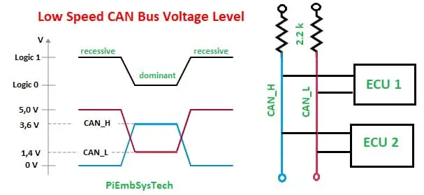
The Low Speed CAN basically be used for 40 kbps to 125 kbps CAN bus. This is also called a fault-tolerant CAN bus. This kind of CAN bus also can run without a termination resistor.
- Dominant Voltage Level: CAN-L is 1.4 v and CAN-H is 3.6 v
- Recessive Voltage Level: CAN-L is 0 v and CAN-H is 5 v.
- High-Speed CAN Physical Layer:
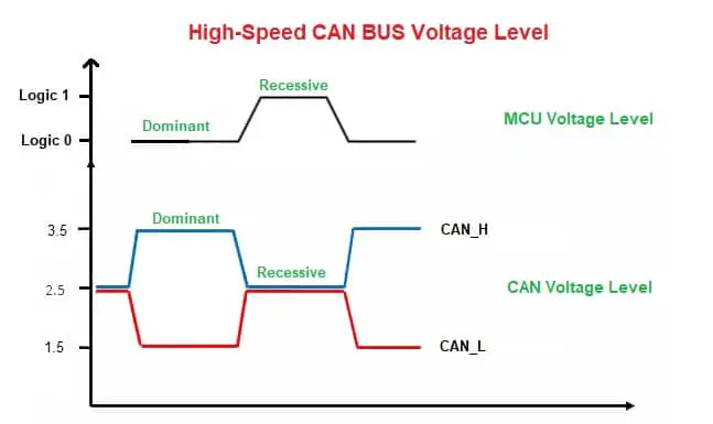
The High Speed CAN basically be used for 40 Kbps to 1 Mbps data rate. This kind of bus must be terminated with a termination resistor from 108 Ohm to 132 Ohm as per bus system-specific.
Dominant Voltage Level: CAN-L is 1.5 v and CAN-H is 3.5 v.
Recessive Voltage Level: CAN-L is 2.5 v and CAN-H is 2.5 v.
As per CAN generation Improvement, CAN is categorized as:
- Classical CAN: Normal CAN protocol having speed up to 1 Mbps with a maximum of 8-bytes of Payload in a single data packet.
- Advanced CAN: CAN-FD(Flexible Data Rate) having speed up to 8 Mbps with a maximum of 64-bytes of payload in a single data packet.
- As per Data Rate, CAN is categorized as:
- Low-Speed CAN: Speed between 1 kbps – 125 kbps.
- Medium-Speed CAN: Speed between 125 kbps – 500 kbps.
- High-Speed CAN: Speed between 500 kbps – 1 Mbps.
- Ultra High-Speed CAN (CAN-FD): Speed between 1 Mbps – 8 Mbps.
- As per Length, CAN is categorized as:
- Class-A: 50 Kbps speed at 1 Kilo Meter (1000 meter) of CAN bus length.
- Class-B: 125 Kbps speed at 500 Meters of CAN bus length.
- Class-C: 1 Mbps speed at 40 Meters of CAN bus length.
- As per Identifier, CAN is categorized as:
- Basic/Standard CAN: Message Identifier is 11-bit (211 = 2048) which helps to create limited unique messages or message identifiers for the lowest number of ECU with lowest data communications in simple CAN networks.
- Extended CAN: Message Identifier is 29-bit (229 = 536,870,912) which helps to create millions of unique messages for data communications in complex CAN networks.
ISO Layer Used In CAN protocol
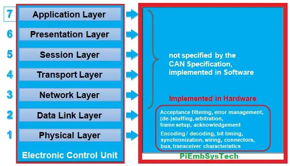
As we all know that each computer system follows the 7-layers of the OSI (Open System for Interconnection) layer for communication between two or more computers. In the automotive field, each ECU’s are nothing but a computer system that used the same OSI layer as shows in the below image:
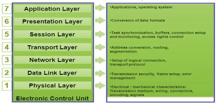
General OSI Layer Design
Among all of the OSIlayers, CAN protocol uses only two-layer since it is a part of an ECU for data or information communication. So for communication purposes, it is sufficient for most of the protocol. These layers are:
- Physical Layer: It defines the CAN transceiver characteristics.
- Data-link Layer: It defines the CAN controller characteristics.
CAN Protocol OSI Layer Design
The Physical Layer is divided into 3-types:
- PLS: Physical Signalling Characteristics defines the bit encoding/decoding, bit timing, synchronization.
- PMA: Physical Medium Attachment defines the CAN transceiver characteristics.
- MDH: Medium Dependent Hardware defines the wiring, connectors, BUS, etc.
The data-link layer is divided into two types:
- LLC: Logical Link Control defines the acceptance filtering, overload notification, and error recovery mechanism.
- MAC: Medium Access Control defines the data encryption/decryption, frame setup, bit stuffing/de-stuffing, collision detection, arbitration, Acknowledgement, error management, etc.
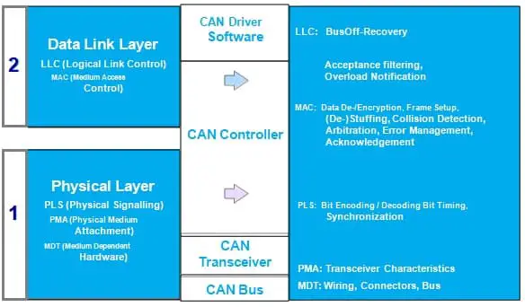
CAN Protocol OSI Layer Detailed Design
What are the Types of CAN Protocol Frames
I hope you would have cleared about all the types of CAN protocol available but commonly one type which I missed and going to explain here because it is common for each type of CAN which I have explained above.
As per CAN frames by which all the CAN standards are communicating among the ECU in a CAN network. There are 5 types of CAN frames such as:
- Data Frame:Used to send the data in a CAN network.
- Remote Frame: Used to request the data in a CAN network.
- Error frame: Used to send the error information in a CAN network.
- Overload Frame: Used to notify the incomplete data reception.
- Inter-Frame Space (IFS): Used to delay the next packet data transmission.
I hope we will not waste the time, Lets go discuss each frame in detail below:
Data Frame Format In CAN Protocol
The data frame in the CAN protocol is used to send/broadcast the data in the CAN network so that others can receive whoever all are available in the CAN network according to their requirement if they need. The data frame having consisted of 7 fields that are taking care of secure data transfer from transmitter to receiver successfully.
Basically, there are two types of data frames according to the frame as the standard frame (11-bit ID) and the extended frame (29-bit ID). First, let’s go discuss the standard CAN frame after then we will discuss the Extended CAN frame.
Standard or 11-bit CAN Protocol Frame Format
The standard CAN was first invented by BOSCH where the maximum of (211 = 2048 unique messages can be generated and used in a CAN network for data communication. The total frame is divided into 7 typical fields which help to identify, detect, correct, validate a CAN message in the CAN network. Please look at the below figure as shown:
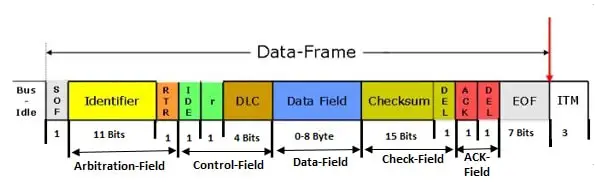
11-bit CAN Standard Frame
CAN Protocol Frame Field Explanation
A Data frame is composed of seven different bit fields: Start of the frame, Arbitration field, Control field, Data field, CRC field, ACK-field, End of the frame. The Data field can be of length zero. Each field is explained below as:
SOF Field In CAN Protocol Data Frame
The Start of frame marks to the beginning of Data frames and remote frames. It is consists of a single dominant bit. A node is only allowed to start transmission when the bus is idle. All the nodes have to synchronize to the leading edge caused by the Start of the frame of the node starting transmission first.
Arbitration Field In CAN Protocol Data Frame
The arbitration field having consisted of different bit fields for different purposes. In 11-bit can, The identifier is 11-bit and the RTR is 1-bit dominant.
11-Bit Identifier: The Identifier field is the heart of the CAN data frame. There are two main purposes of this identifier field is:
- To determine which node needs to gain the bus access whenever more than one node trying to send the messages on the same can bus.
- To identify the type of message it is. That means in can protocol it is message-based so there is nothing like an address for any ECU. It will broadcast whoever interested they will receive it. Now you tell how it will get to know which data he needs to receive or not? Yes for this in CAN protocol, each identifier is unique and it will be assigned to a message. These data including some more data will create a database called a CAN database.
RTR: It is extended for the Remote Transmission Request. The main objective of this bit is to identify either a data frame or a remote frame. If the RTR bit is 1, it is data a remote frame else it is a data frame.
Control Field In CAN Protocol Data Frame
The Control field consists of six bits. It includes the Data length code and two bits reserved for the future of the expansion. The reserved bits must be sent as dominant. Receivers accept dominant and recessive bits in all the combinations.
- DLC: This Data length code is 4 bits wide and is transmitted within the Control field. The DLC bits can code data lengths from 0 to 8 bytes. If the DLC is more than 8 then it is considered a don’t care condition and it will get rejected by the Transmitter ECU.
- IDE: If the Identifier Extension bit is Dominant then it is a standard (11-bit ID) CAN and if the IDE bit is recessive then it is an Extended (29 bit ID) CAN.
- R0: This is a reserved bit for future use. It might be used in the future CAN standard amendment. It is always recessive in the CAN data field.
- Data Field: The Data field consists of data to be transferred within the Data frame. It can contain from 0 to 8 bytes, each of which contains 8 bits which are the transferred MSB first.
CRC Field In CAN Protocol Data Frame
The CRC field contains the 15-bit CRC Sequence followed by 1-bit CRC Delimiter. The CRC field is nothing but an algorithm or a polynomial function you can say. This function will be implemented in all the ECUs available in the CAN network. If you will give the same input, then the output will be the same for all. So when a transmitter will send a data frame, it will give the SOF, Arbitration, Control, and data field data as input and it will generate a 15-bit CRC data that will get added in the CRC field of the CAN data field.
Then the Transmitter ECU will generate the total frame and it will send it over the CAN bus. Then the receiver ECU will receive it. The receiver ECU also has the same CRC algorithm. It will also give the received SOF, Arbitration, Control, and data field as input to that algorithm. Then it will generate a 15-bit CRC field and the controller will compare both the received CRC and generated CRC. If both the CRC is the same it will receive the data or else it will generate the CRC error.
CRC Delimiter: The CRC Sequence is followed by the CRC Delimiter which consists of the single recessive bit.
ACK Field In CAN Protocol Data Frame**
The ACK field is two bits long and contains the ACK Slot and of the ACK Delimiter. In the ACK field, the transmitting node sends two recessive bits. A RECEIVER that has received a valid message correctly reports this to the TRANSMITTER by sending a dominant bit during the ACK Slot (i.e. it sends ACK).
ACK Delimiter: The ACK Delimiter is the second bit of the ACK field and has to be a recessive bit. As a consequence, the ACK Slot is surrounded by the two recessive bits (CRC Delimiter, ACK Delimiter).
End Of Frame In CAN Protocol Data Frame
Each Data of the frame and Remote frame is delimited by a flag sequence consisting of seven recessive bits. The 7 recessive bit is fixed to confirm the idle state of CAN BUS.
Extended or 29-bit CAN Protocol Frame Format
There are two types of CAN protocol defined in ISO 11898-1 standard. Both standards are designed by Robot BOSCH. You would have thought why there are two types of CAN? Yes obviously, let me explain this. Basically, the main difference is the CAN data frame. In this data frame, the Arbitration and control field is having some change, except this, there is no more change in between them.
The main purpose or the advantage of the 29-bit CAN over the 11-bit CAN is that a more number of unique CAN messages can be created. This is required if you have more functionality and data you are going to use in your vehicle, then it is not possible in an 11-bit CAN. So the 29-bit CAN be used in this case. The below image is showing the 29-bit CAN frame format.
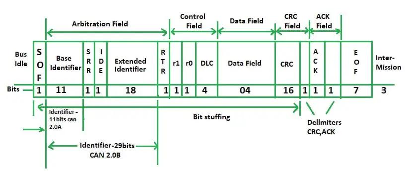
29-bit CAN Frame Format
The above figure, it is showing each and every bit field with clear visibility. As I have already told you except for the arbitration and Control field, others are the same, we will only discuss these fields.
SRR: The SRR is extending for Substitute Remote Request. This bit is always recessive in the extended frame format. If we are using the CAN-2.0B CAN in our CAN system which is supporting both the 11 bit ID and 29 bit ID, but the problem is why we are using this bit. Then we have to think if suppose simultaneously both 11-bit ID as a data frame and the 29-bit ID as the remote frame is trying to send the message. At the same time, the arbitration technology using to gain the bus access.
Then in 11-bit ID, the RTR bit is in the 12th number bit whereas in 29-bit ID it will be in the 30th number bit where the arbitration will gain by the remote frame which is then violating the CAN rule. So to not happen this they have added an SRR bit which is always recessive and used to give the bus access to the 11-bit Identifier instead of violating the BUS access rule.
R1 and R0: The Extended frame is having two reserve bit in the control field like R0 bit in the 11-bit CAN.
CAN Protocol Remote Frame Format
In CAN, there are two types of communication. One is the sender and receiver and the second one is client-server communication. The sender-receiver means when the data will get updated the Transmitter ECU will send it on the CAN bus, and whoever needs it will receive it. In the case of a Client-server, when an ECU needs any data like the vehicle speed in Instrument cluster ECU, it will send a remote frame to the CAN bus.
Then the ECU suppose VMCU ECU who is having this data will receive by checking the RTR bit of that remote frame. After then the VMCU ECU will read the vehicle speed from the sensor and put it in the data field of the same frame and makes the RTR bit 0. Then the VMCU will send it again back and the Instrument ECU will receive it.
A node acting as a RECEIVER for certain data can stimulate the relevant source node to transmit the data by sending a Remote the Frame. A Remote frame is composed of six different bit fields: Start of the frame, Arbitration field, Control field, CRC field, ACK field, End of the frame.
The RTR bit of a Remote the frame is always recessive (cf. Data frames where the RTR bit is dominant). There is no Data field in a Remote frame, irrespective of the value of the Data length code which is that of the corresponding Data frame and may be assigned any value within the admissible range from 0-8.
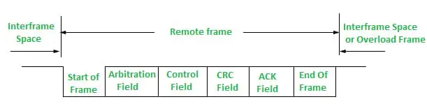
CAN Remote Frame Format
The polarity of the RTR bit indicates whether a transmitted frame is a Data frame (RTR bit dominant) or a Remote frame (RTR bit recessive).
CAN Protocol Error Frame Format
The error frame is used to notify an error that has occurred during the transmission. The error frame consists of an error flag and an error delimiter. The Error frames are transmitted by the hardware part of the CAN controller.
The Error Frame in CAN protocol having consists of an Error Flag, which is having 6 bits of the same value, and an Error Delimiter, which is 8 recessive bits. The Error Delimiter provides some space so that the other nodes on the bus can send their Error Flags when they detect the first Error Flag.
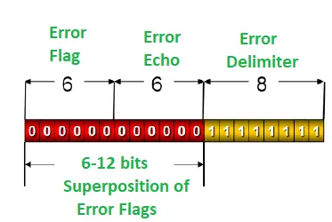
CAN Error Frame Format
The CAN protocol error frame is having two fields:
- Error Flag
- Delimeter Flag
Error Flag: The error flag bits are the minimum of 6 bits which generates whenever any error will occur in the CAN network at the time of data transmission. There are two types of error flags: the active-error flag and the passive-error flag.
- Active-Error flag: 6-12 consecutive dominant bits.
- Passive-Error flag: 6-12 consecutive recessive bits.
Active Error Flag: The Active Error flag consists of six consecutive dominant bits.
Passive Error Flag: The passive Error flag consists of six consecutive recessive bits unless it is overwritten by the dominant bits from other nodes.
Depending on the timing at which an error is detected by each unit connected to the bus, error flags may overlap one on top of the other, up to 12 bits in total length. This is called an overlapping of the error flag.
Error Delimiter: The error delimiter consists of 8 recessive bits.
CAN Protocol Overload Frame Format
The overload frame is used by the receiver unit to notify that it has not been prepared to receive frames yet. It consists of the overload flag and an overload delimiter. There are three kinds of the Overload condition which lead to the transmission of an Overload flag:
- Where the internal conditions of the receiver are such that the receiver requires a delay of the next Data frame or Remote the frame.
- On detection of a dominant bit during the INTERMISSION.
- If the CAN node samples a dominant bit at the eighth bit (i.e. the last bit) of an Error Delimiter or Overload Delimiter, it will start transmitting an Overload frame (not an Error frame). The Error Counters will not be incremented.
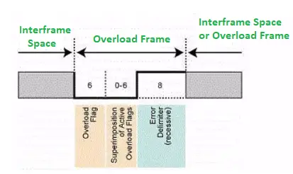
CAN Overload Frame Format
An Overload frame resulting from the Overload condition 1 is only allowed to start at the first-bit time of an expected INTERMISSION, whereas Overload frames resulting from Overload conditions 2 and 3 starts one bit after detecting the dominant bit.
Overload Flag In Overload Frame Of CAN Protocol
It consists of 6 dominant bits. The overload of the flag is structured the same way as the active-error flag of the error frame. The Overload flag’s form destroys of the fixed form of the INTERMISSION field. As a consequence, all other nodes also detect an Overload condition and each starts to transmit an Overload the flag. In the event that there is a dominant bit detected during the third bit of the INTERMISSION, then it will interpret this bit as the Start of a frame.
Overload Delimiter In Overload Frame Of CAN Protocol
It consists of 8 recessive bits. The overload delimiter is structured in the same way as the error delimiter of the error frame. The Overload Delimiter is the same form as the Error Delimiter. After the transmission of an Overload flag, the node monitors the bus until it detects a transition from a dominant to a recessive bit.
At this point of time, every bus node has finished sending its Overload flag, and all the nodes start transmission of the seven more recessive bits in coincidence.
Inter-Frame Space In CAN Protocol
The IFS frame is used to separate the data frame and the remote frames. The data and the remote frames, whichever the frame (data, remote, error, or overload frame) may have been transmitted prior to them, are separated from the preceding frame by an inserted inter-frame space. However, no inter-frame spaces are inserted preceding overload and error the frames.
CAN Protocol Working Principle
The CAN bus is an inexpensive, robust vehicle bus standard designed for multiple CAN device communications with one another without a host computer connection. The CAN is also called a multi-master serial bus and the CAN devices on the bus are referred to as nodes.
Two or more nodes are required on the CAN network to communicate. All nodes are connected to each other via a two-wire bus (CAN H and CAN L) and the wires are 120 ohms nominal twisted pairs. Termination resistor commonly 120 ohms is a must in each node in order to suppress the reflections as well as return the bus to its recessive or idle state.
CAN Working principle
Each node in the CAN bus requires the below modules to work together in a CAN network.
- Microcontroller (Host): It decides what the received messages mean and what messages it wants to transmit.
- CAN controller: They are often an integral part of the microcontroller that handles framing, CRC, etc. like the Data Frame, Remote Frame, Error Frame, Overload Frame, and Inter-Frame Space generation.
- CAN Transceiver: It converts the data from the CAN controller to the CAN bus levels and also converts the data from CAN bus levels to a suitable level that the CAN controller uses.
The transceiver drives or detects the dominant and recessive bits by the voltage difference between the CAN_H and CAN_L lines. The nominal dominant differential voltage is between 1.5V to 3V and the recessive differential voltage is always 0V.
The CAN transceiver actively drives to the logical 0 (dominant bits) voltage level and the logical 1 (recessive bits) are passively returned to 0V by the termination resistor. The idle state will always be in the recessive level (logical 1).
Individually, CAN_H will always be driven towards supply voltage (VCC) and the CAN_L towards 0V when transmitting to the dominant (0). But in a practical case, supply voltage (VCC) or 0V cannot be reached due to the transceiver’s internal diode drop. CAN H/L will not be driven when transmitting a recessive (1) where the voltage will be maintained at VCC/2.
The following figure depicts the block diagram and real-time capture of the CAN signals.
CAN have different physical layers which classify certain aspects of the CAN network such as signaling scheme, cable impedance, maximum data rates, electrical levels, etc. The following are the most commonly used physical layers.
How CAN Communication Works?
As mentioned early, CAN is a Peer-to-Peer network in which there is no master that controls the transmission between nodes. When any CAN node is ready to transmit data, it should undergo a process called message arbitration. In this process, the CAN node will check to see if the bus is idle and starts the transmission once it is idle.
This will also trigger other CAN nodes in the bus and hence results in two or more nodes starting a message at the same time which results in a conflict. The conflict is resolved in the following methods,
The transmitting node monitors the bus while they are sending data If any node detects a dominant level (logical 0) while sending a recessive level itself, it will fail in the arbitration process, and quits immediately will start acting as a receiver. This arbitration process is performed while sending off the arbitration ID field of the CAN frame and in the end, only one transmitter is left on the bus i.e. the node with the highest priority (lowest arbitration ID) will pass the arbitration.
Then the node which has won the arbitration will continue message transmission as if nothing had happened. Other receiving nodes can decide if a message is relevant or if it should be filtered using a combination of hardware and software filters. This process is continuous and other nodes will transmit their messages when the bus has become available.
Operation Of The CAN Network
- Each node is then assigned a unique identification number called the Physical Address of the ECU.
- All the nodes are interesting to transmit compete for the channel by transmitting a binary signal based on their identification value.
- A node will drop out of the competition if it detects a dominant state while transmitting a passive state.
- Thus the node which is having the lowest identification value will win the bus network and start the transmission of the message.
- If any error detects either the transmitter or receiver, it stops the sending of Data Frame and start sending the Error Frame. The error is having an error states to handle the error in CAN Protocol called Error Handling in CAN Protocol. There are 5 types of error in CAN protocol that can occur.
Related Articles For CAN Protocol
https://piembsystech.com/can-protocol/#extended-or-29-bit-can-protocol-frame-format

若有收获,就点个赞吧
0 人点赞
