课程 mit-6.828 从 2019 年开始,对 xv6 OS 的实现采用了 RISC-V instruction set architecture(ISA)。最后一份基于 x86 ISA 的实现是 2018 年的课程,本文便是基于这个版本撰写的。
关于 xv6 在 PC 上的部署,可参考我的另一篇文章:https://www.yuque.com/terencexie/geekartt/xv6-deploy-notes 。
Materials of xv6
- 2018 official class website:https://pdos.csail.mit.edu/6.828/2018/schedule.html
- xv6-book based on x86 instruction set:xv6-public-rev11.pdf
- xv6-code-book based on x86 ISA:xv6-code-rev11.pdf
- xv6-pdf repository:https://pdos.csail.mit.edu/6.828/2018/xv6/
- xv6 github repository:https://github.com/mit-pdos/xv6-public
- qemu doc:https://qemu-project.gitlab.io/qemu/system/quickstart.html
xv6-code-book 给人的第一眼感觉似乎是代码满天飞,感觉让人眼花缭乱摸不着头脑。但事实却是,xv6-code-book 的组织有着极为精巧的设计,并在第一页(重点是右半部分,下图为「右半部分」的截图)详细论述了其设计结构: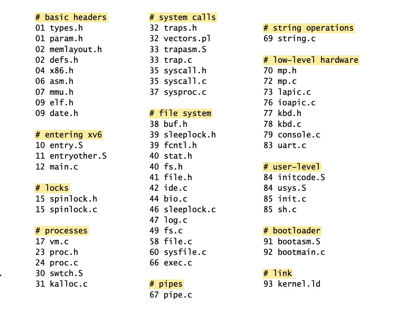
可以看到,这里提供了一份按照 topic 划分的 file list,每个 file 前的 number 是 sheet number,而非 code-line number。
后续的每张代码页,保证了每页仅包含 100 行代码。于是,sheet number 同 code line number 便有了一个对应关系: .
.
如此,我们便能快速定位 xv6-public-rev11.pdf 中对代码的引用。例如,cli (9112) (cli 表示 clear interrupt flag(if),用于关闭 interrupt)可以很快被定位到 sheet number 为 91。又根据上图 sheet number 同 file 的关系可知,它是 topic booltloader 下的 bootasm.S 文件的内容。
上图对应的文本为:
# basic headers01 types.h01 param.h02 memlayout.h02 defs.h04 x86.h06 asm.h07 mmu.h09 elf.h09 date.h# entering xv610 entry.S11 entryother.S12 main.c# locks15 spinlock.h15 spinlock.c# processes17 vm.c23 proc.h24 proc.c30 swtch.S31 kalloc.c# system calls32 traps.h32 vectors.pl33 trapasm.S33 trap.c35 syscall.h35 syscall.c37 sysproc.c# file system38 buf.h39 sleeplock.h39 fcntl.h40 stat.h40 fs.h41 file.h42 ide.c44 bio.c46 sleeplock.c47 log.c49 fs.c58 file.c60 sysfile.c66 exec.c# pipes67 pipe.c# string operations69 string.c# low-level hardware70 mp.h72 mp.c73 lapic.c76 ioapic.c77 kbd.h78 kbd.c79 console.c83 uart.c# user-level84 initcode.S84 usys.S85 init.c85 sh.c# bootloader91 bootasm.S92 bootmain.c# link93 kernel.ld
topic list:
- basic headers
- entering xv6
- locks
- processes
- system calls
- file system
- pipes
- string operations
- low-level hardware
- user-level
- bootloader
- link
除了这份 topic list,xv6-code-book 还提供了一份基于 keyword 的 inverted index。例如:
swtch 26580374 2428 2466 2657 2658
表示 swtch 这个 keyword 被定义于 codeline 2658(如上可知,它在 processes topic 下的 proc.c 文件中),在 codeline 0374 2428 2466 2657 2658 中被分别使用。
这项功能在具备全局搜索功能的 IDE 上当然无足轻重,但如果你手头上没有电脑或者电脑上没有 IDE,而此时又想通过阅读 xv6 来打发时间,那么,这份 keyword inverted index 就是相当顺手的工具。
xv6 entry point
由下图和 xv6-public-rev11.pdf 的 Appendix B 可知,BIOS program 被单独存储于 motherboard 上的一块硬件,如 EEPROM(Electrically Erasable and Programmable ROM)or a flash-memory,计算机启动时会自动直接读取这块硬件的 program 来运行。

BIOS 完成硬件的基本检测后,会直接将 boot disk 中 boot sector 的内容(first 512-byte sector of the boot disk),即 boot loader 的内容,加载到 memory 的 0x7c00 的位置,并将 CPU 的 PC register 设置为 0x7c00 。
显然,根据 CPU 的正常运行流程,它的下一条 instruction 就是读取 0x7c00 位置的内容开始运行,即:读取 boot loader 的内容来运行。
对于 xv6-public 工程来讲,bootasm.S 文件所存放的便是 bootloader 的内容。那么,按照如上论述,bootasm.S 文件必须被放于 disk first sector 中(或 memory 的 0x7c00 位置上),才能让 CPU 在 BIOS 加载完成后首先运行它。
于是,必须将 bootasm.S 放于 qemu 的 disk first sector 中。
Remarks:
.S文件是 assembly code file。值得注意的一个小细节是,.Sfile 不同于.sfile,前者是可以包含 preprocess 的代码的,例如上述bootasm.S文件包含#include语句。而.sfile 是不可以包含 preprocess 的代码。- 虽然 xv6-rev11 的 ISA 是 x86,但 x86 却有各种各样的 assembler,如:MASM、NASM、GAS(GNU Assembler)、as86、TASM、a86、Terse 等。在 xv6 中是使用 GNU assembler 来撰写
.S文件的。GNU assembler 最好的介绍无疑是 CSAPP 的 Chapter 3。另外还可参考的文章是:x86 Assembly Language Programming、GNU Assembler Examples . - 如同 assembler 各式各样,x86 的 object file 的类型也是各式各样,如:
- Linux 下的 ELF, COFF, Win32, OMF, a.out 文件;
- FreeBSD 的 a.out;
- 以及 rdf, IEEE-695, as86 等文件格式。
- 更多关于 x86 assembly 的系统讨论,可参考文章:x86 Assembly Notes 。
- 关于 boot loader:
- 当 boot loader 启动时,processor 其实是处于类似 Intel 8088 的 real mode 状态。所以 boot loader 的主要作用便是:逐步切换到 modern OS 的 protected mode。
- 切换的方式是:通过将 kernel 从 disk 加载到 memory、并将 control 转交给 kernel。
关于 bootstrap:
bootasm.S
根据 xv6 项目根目录的 Makefile 可知:
bootblock: bootasm.S bootmain.c$(CC) $(CFLAGS) -fno-pic -O -nostdinc -I. -c bootmain.c$(CC) $(CFLAGS) -fno-pic -nostdinc -I. -c bootasm.S$(LD) $(LDFLAGS) -N -e start -Ttext 0x7C00 -o bootblock.o bootasm.o bootmain.o$(OBJDUMP) -S bootblock.o > bootblock.asm$(OBJCOPY) -S -O binary -j .text bootblock.o bootblock./sign.pl bootblockkernel: $(OBJS) entry.o entryother initcode kernel.ld$(LD) $(LDFLAGS) -T kernel.ld -o kernel entry.o $(OBJS) -b binary initcode entryother$(OBJDUMP) -S kernel > kernel.asm$(OBJDUMP) -t kernel | sed '1,/SYMBOL TABLE/d; s/ .* / /; /^$$/d' > kernel.symxv6.img: bootblock kerneldd if=/dev/zero of=xv6.img count=10000dd if=bootblock of=xv6.img conv=notruncdd if=kernel of=xv6.img seek=1 conv=notruncqemu: fs.img xv6.img$(QEMU) -serial mon:stdio $(QEMUOPTS)
在 make qemu 的依赖关系中,对 bootblock 的定义有:$(LD) $(LDFLAGS) -N -e start -Ttext 0x7C00 -o bootblock.o bootasm.o bootmain.o ,即:让其从 0x7C00 开始 start。
并且,bootblock.o 是由 bootasm.o 和 bootmain.o 两个文件共同生成的,因此后面才能从 bootasm.o 中访问到 bootmain() 的代码。
概述:
bootasm.S文件首先调用cli指令(cli 表示 clear interrupt flag(if),用于关闭 interrupt)用于关闭 BIOS 所开启的 interrupts。- 在
bootasm.S文件的末尾(9168),通过call bootmain语句调用了bootmain.c的代码。 - 而
bootmain.c的主要工作,则是将 xv6 OS kernel 的 executable file 放入到 second sector,进而加载进 memory 使之运行。
0、当 processor 处于类似于 Intel 8088 的 real mode 时,它有 8 个 16-bit 的 general register。
但 processor 所处理的 memory address 却是 20-bit 的。其中,segment register(real mode 下的 memory 为 segmentation model,而不是 paging model,下文会论述原因)有 4 类:
%cs:code segment, instruction fetch%ds:data segment, data reads/writes%es:extra segment, for far pointer addressing like video memory and such%ss:stack segment, stack reads/writes
用于提供 process 寻址的必要数值。
process 的寻址(reference a memory address)方式:将其中一个 segment register 的值乘以16(即:在末尾 4 位的零),再同 offset 做 bit 相加(此时 offset 的 bit 恰好填补末尾 4 位零的位置),得到作为最终的 memory address。
History:
由 IBM PC Architecture - Intel 8088 “base” architecture 可以看出,IBM 的 bus 是 20-bit 与 CPU Intel 8088 16-bit 的矛盾,导致了 segment 寻址的出现。即:对于 CPU 来讲,它只能给出 16-bit 的地址,于是将其作为 offset,再利用 register 作为 segment 的 index,于是可以通过 segment:offset 的方式来取到特定的地址: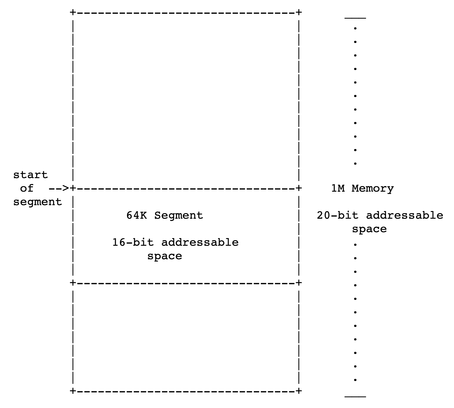
由上图可以看出,在 segment:offset 中,segment 标识的是一个 segment 的起始位置,从这个起始位置后的具体寻址,是由 CPU 的 16-bit(以 10-bit 作为一个单位的拆分,则:16-bit = (6-bit) + (10-bit) = (2^6) KB = 64KB)的 offset 给出的。
※1、bootasm.S 文件首先调用 cli 来禁止处理 interrupt,是因为在此之前是由 BIOS 来处理 interrupt。而此时 BIOS 已经不再运行、由 boot loader 程序接管,而它并不支持 interrupt 的处理。
此时,若继续允许「由不再运行的 BIOS 所处理的」interrupt,是不合适的、也是危险的。于是便直接将其禁止。等到 kernel 被加载到 memory 时,便可以再次允许 interrupt。
2、在 bootstrap 阶段,由于 kernel 还未被加载进 memory,此时 memory 的管理方式还是较为原始的 segment(参考:x86 memory segment,从 Intel 8086 开始引入) 方式(boot loader 不支持 paging hardware),即:(segmentselector, offset) pair,即:_segment:offset,而不是 paging 的方式。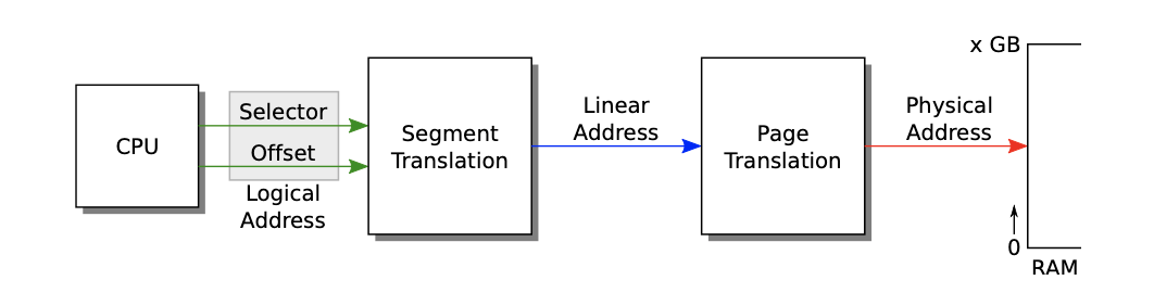
根据上图 logical address(segment:offset)、linear address、physical address 的关系,可以看到:
- logical address ==> linear address:
- 通过 segment:offset 生成 linear address,由 segmentation hardware 来完成。
- linear address ==> physical address:
- 如果 hardware 还支持 paging,则通过 paging hardware 将上述 linear address 转换为 physical address;
- 否则直接将上述 linear address 作为 physical address。
由于 boot loader 不支持 paging hardware、仅支持 segmentation hardware,则它会直接将 logical address 转换的 linear address 直接作为 physical address,即:「linear address == physical address」。
为了简单,xv6 将 logical address 到 linear address 的转换函数设置为「恒等映射」,即:直接将 logical address 作为 linear address,即:「logical address == linear address」。
再根据前面 bootstrap 阶段的等式「linear address == physical address」,则:xv6 在 bootstrap 阶段会直接将 logical address 作为 physical address,即:「physical address == linear address == logical address」。
显然,当 kernel 接管控制时,唯一有意思的 translation 便是 linear address 到 physical address 的转换,它需要通过 OS 的 paging translation 来实现。
※3、由于 BIOS 并不保证 %ds , %es , %ss 的值,因而其首要任务便是将它们初始化,如:设置 %ax 为 0,再将这个 0 copy 到 %ds , %es , %ss (9115-9118)。而 %cs 通常用于 instruction fetch,便不对其做初始化。
※4、virtual segment:offset 有可能会指代 21-bit physical address,但 Intel 8088 仅支持 20-bit 的 memory address,会自动 discard top bit。
例如:对于以 segment:offset 形式存在的 virtual address 0xffff:0xffff 来讲,它的 physical address 应该是:0xffff + 0xffff = 0x10ffef ,但由于 discard top bit 的关系,其 physical address 便只能是 0x0ffef 。
很多早期的 software 便依赖于这种 ignore 21st address 的机制。例如,IBM 提供了 hardware 兼容性的机制:可根据 keyboard controller’s output port 的 2nd bit 的值,来设置是否 ignore 21st address bit。如果是 0,则清除 21st bit;如果 2nd bit 是 1,则保留。
因此,boot loader 需要根据 keyboard controller’s output 在 port 0x64 , 0x60 上的值(通过对 keyboard 的 IO)来判断是否允许 ignore 21st address bit(9120-9136)。
5、通常来讲,segment register 在 protected mode 下的用法应如下图所示: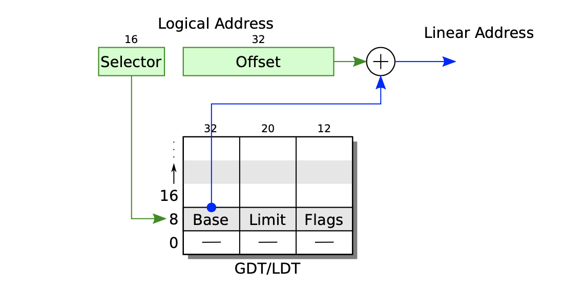
将 segment:offset 中的 segment_selector 作为 segment descriptor table 的 index,图中的 index 为 16(注意到 0、8、16 表示的是 GDT/LDT(Global Descriptor Table/Local Descriptor Table)表格的下边界,所以 index 16 恰好对应到 blue node 的位置)。
Ref:
GDT, Global Descriptor Table, is used to define the characteristics of the various memory areas used during program execution, including the base address, the size and access privileges like executability and writability.
These memory areas are called segments in Intel terminology. (From Wikipedia) Segment is a term for memory management in Intel x86 architecture, which is also used collaboratively with paging mechanism.
LDT, Local Descriptor Table, acts similar to GDT, which also saves segments descriptor. The main differences between GDT and LDT is:
- GDT have only one copy in system while LDT can have many,
- GDT may not changed during execution which LDT often changes when task switches,
- entry of LDT is save in GDT.
Entries in GDT and LDT have the same structure.
Ref:
A Local Descriptor Table (LDT) is like theGlobal Descriptor Tablein that it holdsSegmentdescriptors for access to memory. The difference is that every Task/thread can have its own LDT, and the OS can change the LDT Register (LDTR) on every Task switch. That means that every program can have its own list of memory Segment descriptors, and keep them private from other programs:
- The Code, Data and Heap segments can be private in the LDT - separate from other programs, but available to this program;
- Each Task/thread within this program can have its own Stack in the LDT, and yet still be able to access the above Segments;
- Sharing within the program is automatic: just ‘know’ the correct Descriptor reference;
- If another program (with another LDT) was to attempt to access one of these Segments, it would access its_own_LDT’s Segment rather than the target Segment.
The Local Descriptor Table is a list of descriptors for the current program. It is distinct from the GDT in a number of respects:
- It cannot hold many types of descriptors;
- The GDT holds a reference to the LDT (the Base and Limit of the table in memory);
- It is only accessible by Tasks/threads with the same Local Descriptor Table Register (LDTR) value.
每一条 table entry 包含三部分的内容:
- 「base」:base address
- 「limit」:maximum virtual address
- 「permission」:permission flag bits for the segment
也即是,通过 selector 找到 offset + <base_address> 来生成这个 segment 的 linear address,它在 kernel 中的 permission 由
xv6 其实是忽略了整个 segment 的转换过程,直接使用了 paging hardware。通过将 base 设置为 0,将 limit 设置为整个 memory size(4G),也即是完全将 logical address 直接映射到了 linear address。
bootmain.c
bootmain.c 依赖 kernel ,根据 Makefile 可知,后者由 kernel.ld 来定义 link 的过程(关于 ld 的语法,可参考:https://sourceware.org/binutils/docs/ld/index.html)。
bootmain.c 的入口是 void bootmain(void) 方法,其内容包括:
- 通过
readseg((uchar *) elf, 4096, 0)读取 kernel ELF 文件(在 compile 阶段生成、并在 qemu 的启动参数_QEMUOPTS = -drive file=fs.img,index=1,media=disk,format=raw -drive _**_file=xv6.img_**_,index=0,media=disk,format=raw -smp $(CPUS) -m 512 $(QEMUEXTRA)_中作为_file=xv6.img_出现,所以能够在 runtime 阶段直接读取到对应的 disk 部分);- ELF header 的定义是严格按照 ELF header specification 来定义的。
elfhdr和proghdr对应数据结构中的各字段的意思,都可在此文档中找到。
- 读取 ELF file 的 1st page 到 scratch space(xv6 设定这块 scratch space 是从
0x10000开始;在 Appendix B 的 exercise 部分也提到,这个 magic number 是一个 arbitrary location,具有一定的危险性),用于 user data 的暂存。 - 通过
elfhdr的magic字段是否等于ELF_MAGIC来确认是否是 ELF 文件(_elfhdr_和_ELF_MAGIC_均定义于_elf.h_文件中,而_elf.h_所使用到的类型,如_uint_,_ushort_定义于_types.h_文件中)。
- ELF header 的定义是严格按照 ELF header specification 来定义的。
- 使用
readseg读取 program segment; - 使用
rep stosb初始化 memory; - 通过
entry()调用 kernel entry point(通过__start_symbol 来定义,对 xv6 来讲它的值是_0x10000c_),它被定义于 entry (1044)。
// 端口 I/O 描述inb, inw, inl,outb, outw, outl,inb_p, inw_p, inl_p,outb_p, outw_p, outl_p,insb, insw, insl,outsb, outsw, outsl,
This family of functions is used to do low level port input and output:
- The
out*functions do port output; - the
in*functions do port input; - the
_p-suffixfunctions pause until the I/O completes; - the
b-suffixfunctions are byte-width; - the
w-suffixfunctions word-width; - the
l-suffixfunctions long-width.
- The “inb”, “inw” and “inl” commands perform an input (read) operation on the given I/O port, and print the result.
- The “outb”, “outw” and “outl” commands perform an output (write) operation to the given I/O port, sending the given data. Note that the order of the parameters is ADDRESS DATA.
- The size of the operation is selected according to the suffix, with
bmeaning byte,wmeaning word (16 bits) andlmeaning long (32 bits).
通过 bootmain.c 的代码,xv6 将 kernel 从 disk 加载到 memory(加载到 0x10000 地址;在 kernel starts 的这一阶段,paging hardware is not enabled;此时,由 xv6 对 segment 映射的简化知 virtual memory 是等同于 physical memory 的 ),并从 entry.S 文件中的 entry(1044) 开始执行。
entry.S
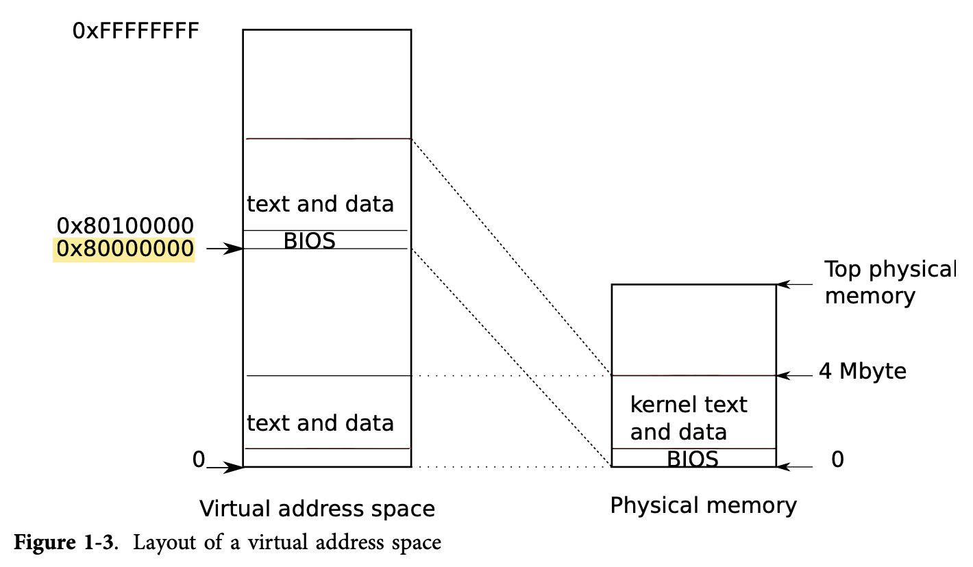
上一步 boot loader 将 xv6 kernel 加载到 0x100000 地址:
- 没有选择
0x80100000是因为在一些 small machine 上没有如此高位的地址; - 没有选择
0x0是因为在0xa000:0x100000包含很多 I/O devices。
在 entry.S 中所做的事情主要是:
- 打开 page size extension for 4M pages
- 设置 page directory
- 打开 paging
- 设置 stack pointer
- jump to main():
mov $main, %eax、jmp *%eax。
而 main() 则是定义于 main.c 文件的 main() 函数。
总结:boot 的完整流程
总结起来,整个 startup 的过程是:
- BIOS 将 1st sector of disk 的 bootblock 代码(包含
bootasm.S和bootmain.o的代码),直接加载到 hardcode 的位置0x7c00(从这里算起的 512-byte area,即:0x27c00 - 1),并将 PC register 设置为0x7c00,以便下一条指令从0x7c00执行。 - 在
**bootasm.S**的最后通过call bootmain语句调用了**bootmain.c**中的bootmain()方法。 bootmain.c将 kernel ELF 的内容从 disk 写入到 memory(由0x10000位置开始写入,这是 xv6 设置的一个 arbitrary location,属于 magic number),并通过语句entry = (void (*)(void)) (elf->entry); entry();(也即是:其调用位置由 kernel ELF File Header 的 e_entry 字段提供)来调用**entry.S**中的entry部分。- bootblock 存放于 disk 的第一个 sector,而 kernel ELF 在 disk 上的保存位置从第二个 sector 开始。
- 由 QEMUOPTS 具体给出对应的 disk 是什么:
_file=xv6.img_。 - 根据传统,ELF 格式中 File Header 的
_entry_字段由__start_这个 symbol 给出,它恰好定义于_entry.S_中,所以执行流程自然就跳转到 entry.S 的 entry 部分。 - 编译完成 kernel ELF 后,可通过
_nm kernel | grep _start_来查看__start_对应的值:_0010000c T _start_,以验证上述说法。
entry部分做完开启 paging、设置 stack pointer 后,最终通过mov $main, %eax、jmp *%eax跳转到**main.c**文件的main()函数。- 由 kernel ELF 在 Makefile 中的定义
$(LD) $(LDFLAGS) -T kernel.ld -o kernel entry.o $(OBJS) -b binary initcode entryother可知,entry.S已经同 kernel 部分通过ld链接到了一起,所以mov $main, %eax中是可以找到 symbolmain的具体 memory address 的。
- 由 kernel ELF 在 Makefile 中的定义
First Allocation/Execution
创建 first address space
在上述的 boot load 的过程中,entry.S 顺道做了对 first address space 的分配工作:
- entry page table(
entrypgdir)定义于main.c中, - 将 entrypgdir 的地址保存于 register
%cr3中(此时为 physical address,因为还未开启 paging,所以设置为 virtual address 没有意义)。 - 为开启 paging,通过设置 register
%cr0的CR0_PGflag 来实现:orl $(CR0_PG|CR0_WP), %eax. - 虽然开启了 paging,但此时的 instruction 依旧在 low address(低于 kernel base 的 address)工作。但下一步,执行流程需要到 kernel C code 的部分。而 C code 部分是需要在 high address 执行 virtual memory address 的。所以在切换之前,需要让 instruction 的执行切换到 high address。
- 设置
%esp到高位:movl $(stack + KSTACKSIZE), %esp(因为 stack 的使用,完全是相对于%esp的取值而定的。所以,如果将%esp的值切换到了 high address,那么自然,后续对 stack 的使用便都是相对于这个 high address 了)。 - 使用 indirect jump 到
main方法。否则,PC-relative 的 direct jump 会让 main 的执行出现在 low address 部分。 - 如此,便完成了「low address 代码执行」到「high address 代码执行」的切换。
- 设置
创建 first process
(这部分的内容,可见 xv6 book Code: the first address space 部分)
完成 boot load 的部分后,xv6 的执行流程便从 main.c 的 main() 开始了。在 main() 方法中,首先完成了 device 和 subsystem 的初始化。
之后开始最重要的工作:创建第一个 user process(对应到 main.c 的 main() 中,尾部语句 userinit(); 的调用)。
而 userinit(); 定义于 proc.c 中,其工作是:
- 调用
allocproc方法,扫描 proc table 中的 unused slot。 - 如果未找到,直接返回 0.
- 如果找到,则:
- 修改 state 为 EMBRYO,以此标识为 used
- 分配 pid
- 为这个 unused slot 分配 kernel stack
- ……
- 调用
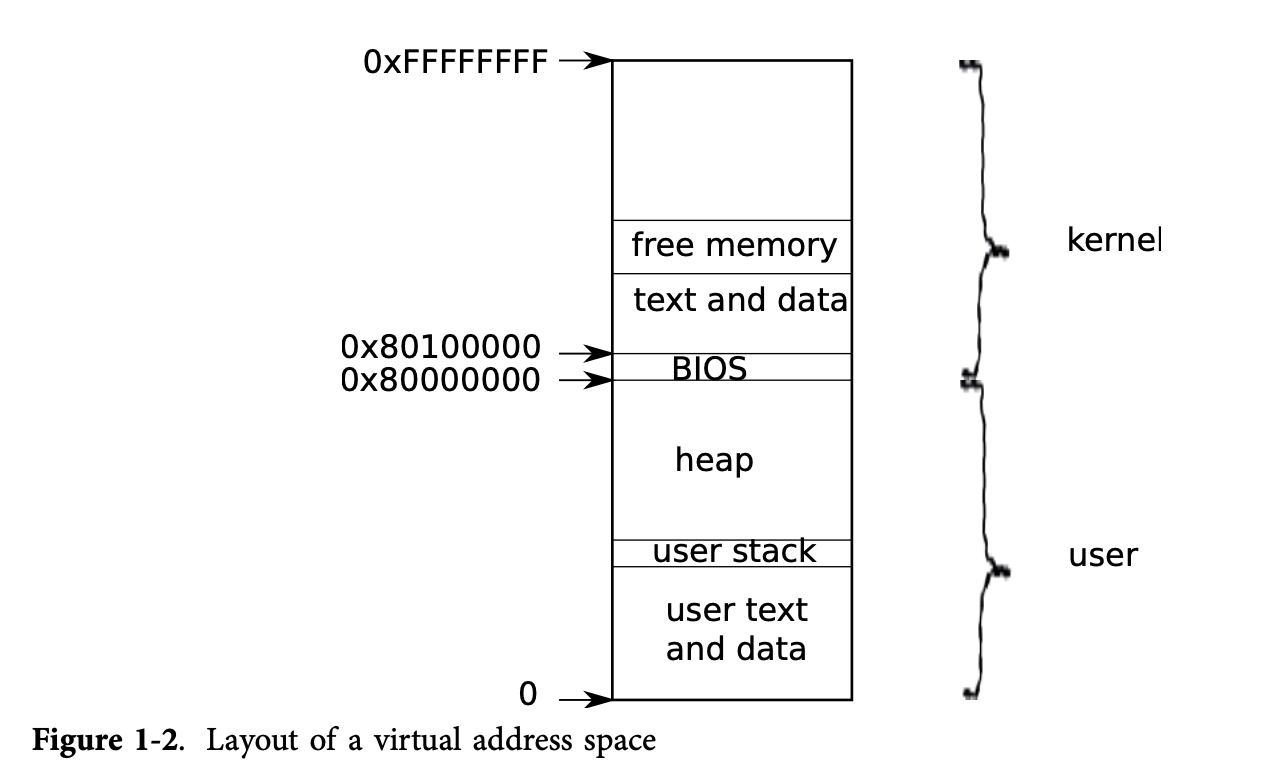
setupkvm()方法(switch to kernel VM?),用于为 process 创建如 Figure 1-2 那样 layout 的 page table。 - 设置这个新获得的
p->state为 RUNNABLE,以标准 first process 已经准备完成。
执行 first process
main.c#main()调用完userinit()后,调用mpmain()方法:通过调用scheduler来启动 first process running。- ……
First system call exec
initcode.S中调用了exec这个 system call:movl $SYS_exec, %eax和int T_SYSCALL。
Memory Layout
物理地址的对应内容: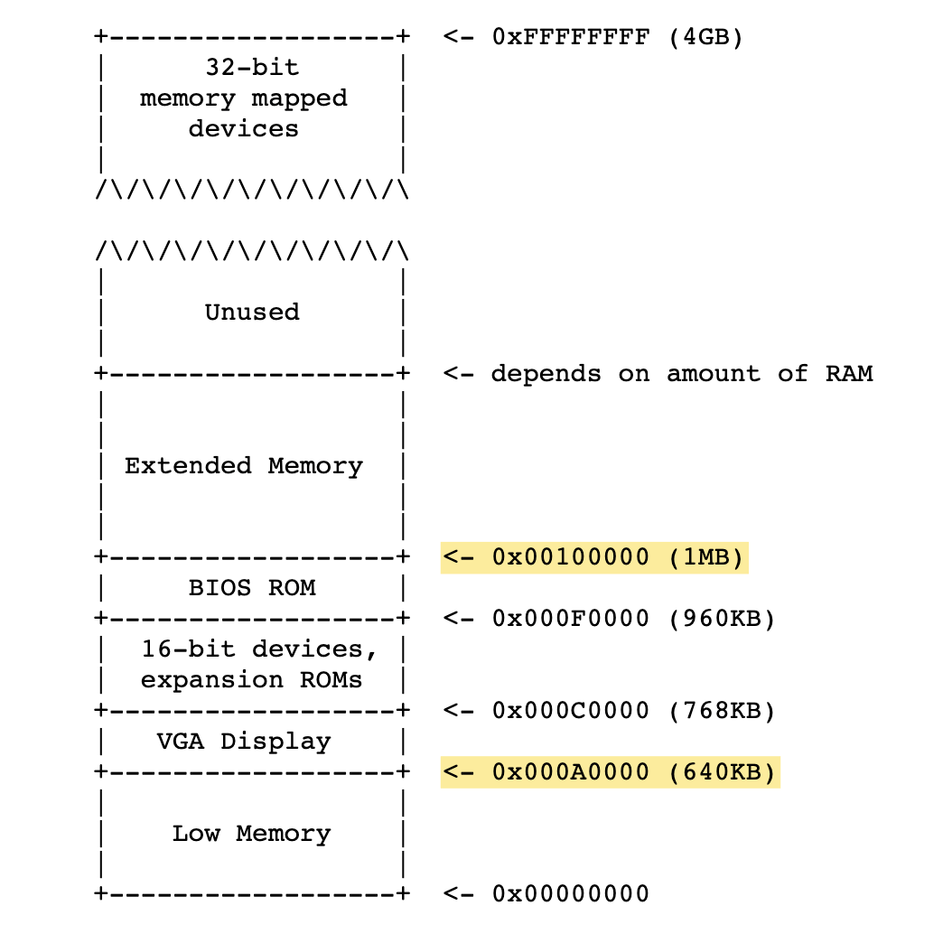
由 32-bit 的 memory 被 16-digit 表示,则有:2^32 = (2^4)^8 = (16)^8,即:8-bit 的 16-digit 才能完整表示 32-bit 的 memory,所以,其起始位置的值应该是:0x00000000 (8位)。
0x00100000-0x00400000 xv6 OS (not filled)0x000A0000-0x00100000 device# --- Low Memory ---0x00010000-0x00011000 kernel ELF header (4096 bytes)0x00007c00-0x00007d00 boot loader code (512 bytes)0x00000000-0x00007c00 boot loader stack

若有收获,就点个赞吧
0 人点赞
