模拟输入输出串口
这个例子展示怎么读取一个模拟输入引脚,并把结果按0-255的范围分配。用那个结果来设置一个输出引脚的脉冲宽度(PWM)来变暗或者变亮一个LED等,并打印这个值到Arduino IDE软件的串口监视器。
硬件要求
- Arduino or Genuino 开发板
- 电位计
- 红色LED灯
- 220 ohm 电阻
电路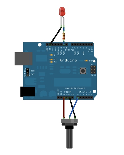
连接一个电位计的引脚到5V,中间的引脚到模拟引脚pin0,最后的引脚接地。然后串联一个LED灯()和一个220 ohm电流限制电阻到数字引脚pin9。LED灯的长,正极的引脚连接到电阻的输出端,而短,负极的引脚接地。
原理图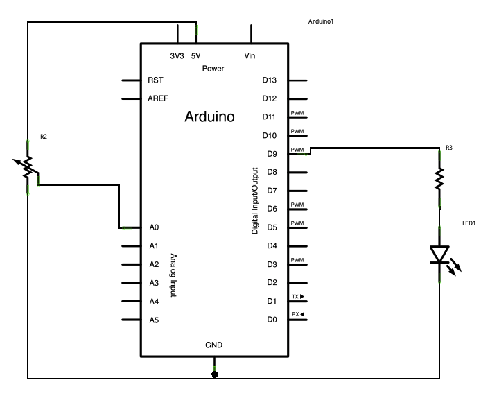
样例代码
在下面的程序,声明两个引脚的分配(电位计的模拟引脚pin0和LED的数字引脚pin9)和两个变量,传感值和输出值。你唯一要在setup()函数里做的就是开始串口通讯。
然后,在主循环里,传感值用来保存从电位计读取的未处理的模拟值。Arduino的模拟读取范围是0到1023,而模拟写入范围是0到255,因此从电位计出来的数据需要在使LED灯变暗之前转化成小范围的对应值。
为了转化这个值,使用一个叫map()的函数:
outputValue = map(sensorValue, 0, 1023, 0, 255);
输出值用来匹配从电位计出来的换算值。map()包括5个argument:映射值,输入的最低最高值,映射的最低最高值。在这种情况下,传感数据从它的0-1023初始范围映射到0-225范围。
最新的映射后的传感数据输出到模拟输出引脚来使LED变亮或变暗,就好像电位计在调节那样。最后未处理值和已换算值都发送到Arduino IDE软件的串口监视窗口里。
/*Analog input, analog output, serial outputReads an analog input pin, maps the result to a range from 0 to 255and uses the result to set the pulsewidth modulation (PWM) of an output pin.Also prints the results to the serial monitor.The circuit:* potentiometer connected to analog pin 0.Center pin of the potentiometer goes to the analog pin.side pins of the potentiometer go to +5V and ground* LED connected from digital pin 9 to groundcreated 29 Dec. 2008modified 9 Apr 2012by Tom IgoeThis example code is in the public domain.*/// These constants won't change. They're used to give names// to the pins used:const int analogInPin = A0; // Analog input pin that the potentiometer is attached toconst int analogOutPin = 9; // Analog output pin that the LED is attached toint sensorValue = 0; // value read from the potint outputValue = 0; // value output to the PWM (analog out)void setup() {// initialize serial communications at 9600 bps:Serial.begin(9600);}void loop() {// read the analog in value:sensorValue = analogRead(analogInPin);// map it to the range of the analog out:outputValue = map(sensorValue, 0, 1023, 0, 255);// change the analog out value:analogWrite(analogOutPin, outputValue);// print the results to the serial monitor:Serial.print("sensor = ");Serial.print(sensorValue);Serial.print("\t output = ");Serial.println(outputValue);// wait 2 milliseconds before the next loop// for the analog-to-digital converter to settle// after the last reading:delay(2);}
- map()
- analogRead()
- analogWrite()
- serial()
- AnalogInput - 用电位计来控制LED灯闪烁
- AnalogWriteMega - 永一个Arduino或者Genuino Mega开发板来使12个LED灯一个接一个逐渐打开和熄灭
- Calibration - 定义期望中的模拟传感值的最大值和最小值
- Fading - 用模拟输出(PWM引脚)来使LED灯变亮或者变暗
- Smoothing - 使多个模拟输入引脚的读取值变得平滑

若有收获,就点个赞吧
0 人点赞
