模拟输入
在这个例子里我们用一个变化电阻(一个电位计或者光敏电阻),我们通过Arduino或者Genuino开发板的一个模拟输入引脚读取它的值,并且根据这个值改变内置LED灯闪烁的速率。这个电阻的模拟值是作为电压读取,因为这是模拟输入的工作方式。
硬件要求
- Arduino or Genuino 开发板
- 电位计 或者 10K ohm 光敏电阻和 10K ohm 电阻
- pin13引脚的内置LED灯 或者 220 ohm 电阻和红色LED灯
电路
带电位计: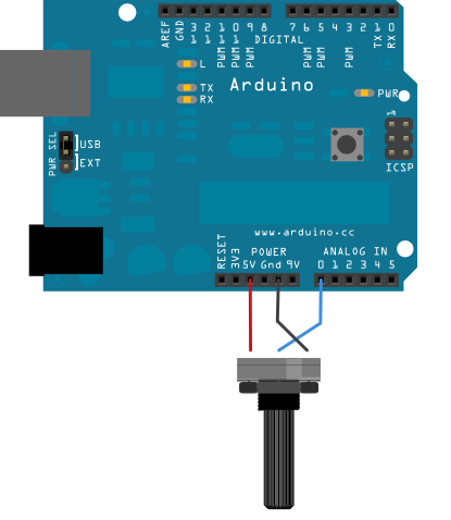
带光敏电阻: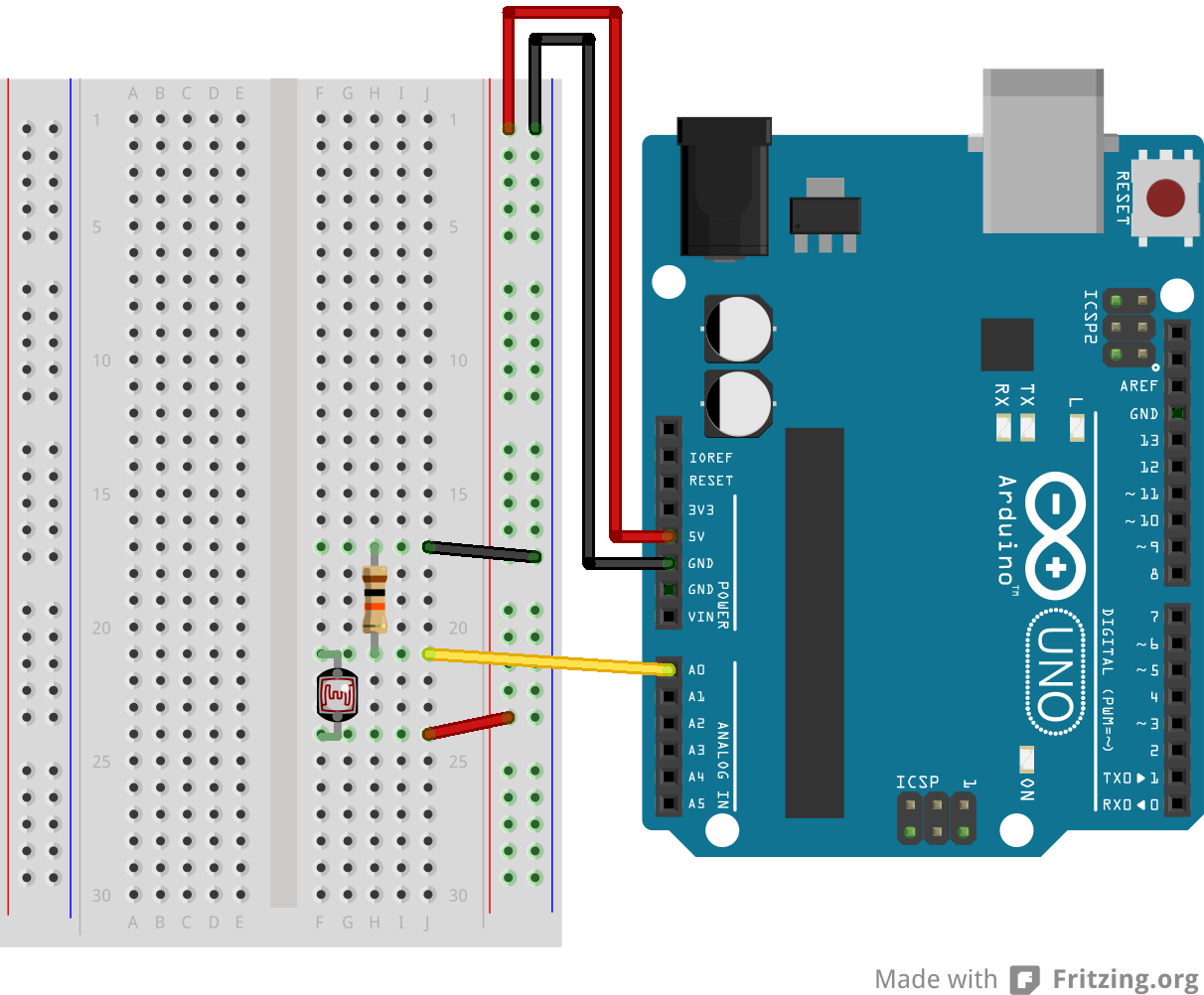
- 连接三根线到开发板。第一根从地到电位计的一个引脚。第二根从5V到电位计的另一个引脚。第三跟从模拟输入引脚A0到电位计的中间引脚。
- 这个例子里,可以使用开发板的连接到pin13的内置LED灯。如果用外加的LED灯,把它的长脚(正极或者阳极)串联一个220 ohm电阻,再连接到数字引脚pin13,而它的短脚(负极或者阴极)连接到pin13旁边的GND引脚(地)
这个电路基于光敏电阻,用一个分压器来使高阻抗模拟输入引脚来测量电压值。这些输入引脚不吸取任何电流,因而根据欧姆定律,这些在电阻的一端连接到5V的被测量的电压等于5V,而不管这些电阻值。为了获得按光敏电阻值匹配的电压值,一个电阻分压器是很有必要的。这个电路用一个可变电阻器,一个固定电阻,而测量点是在这些电阻值的中间。测量的电压(VOUT)符合以下公式:
Vout=Vin*(R2/(R1+R2))
其中Vin为5V,R2为10kohm和R1为光敏电阻值(范围从在黑暗的1M ohm到在亮处(10lumen)的10k ohm,再到光亮处(>100lumen)的1k ohm)。
原理图
电位计: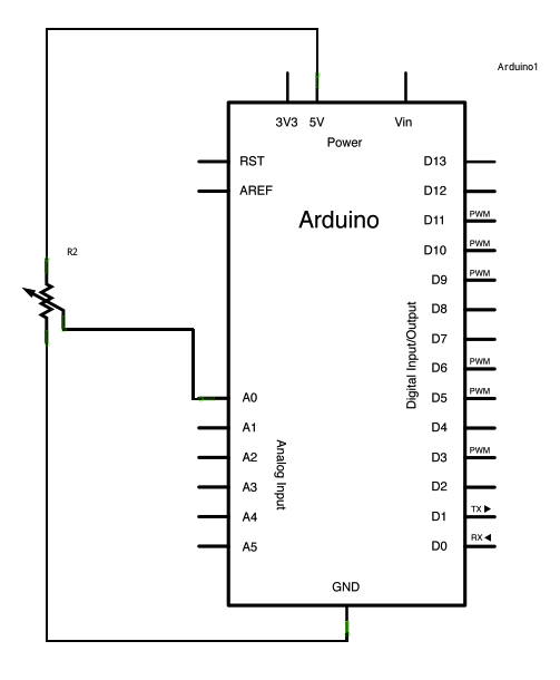
光敏电阻: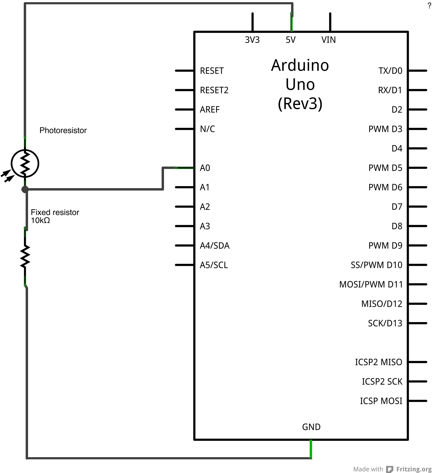
样例代码在程序开始部分,变量感应引脚被设置为模拟引脚A0,那个地方连接着电位计。ledPin被设置为数字引脚pin13.你也可以创建另外的变量,sensorValue来保存从你传感器里读到的值。
- 用 analogRead() 命令转化输入电压范围(0-5V)到数字值(0-1023)。这个可以用叫模拟数字转换器或者ADC的微控制器来实现。
- 通过转动电位计的轴,你可以改变电位计的电阻值。这会改变在中间引脚和其他两个外接引脚之间的电阻值,在模拟输入引脚处产生一个电压差。当轴转向一个方向,中间引脚和地引脚没有阻抗。中间引脚的电压值为0V,并且analogRead()返回0.当轴转向另一个方向,中间引脚和5V引脚没有阻抗。中间引脚的电压值为5V,并且analogRead()返回1023。转轴在之间时,analogRead()返回0-1023之间的一个数。
这个值,保存到sensorValue,用来为你的闪烁周期设置 delay() 。这个值越高,周期越长;越低,周期越短。在周期循环之前读取这个值,因此每次开/关的时间总是一样的。
/*Analog InputDemonstrates analog input by reading an analog sensor on analog pin 0 andturning on and off a light emitting diode(LED) connected to digital pin 13.The amount of time the LED will be on and off depends onthe value obtained by analogRead().The circuit:* Potentiometer attached to analog input 0* center pin of the potentiometer to the analog pin* one side pin (either one) to ground* the other side pin to +5V* LED anode (long leg) attached to digital output 13* LED cathode (short leg) attached to ground* Note: because most Arduinos have a built-in LED attachedto pin 13 on the board, the LED is optional.Created by David Cuartiellesmodified 30 Aug 2011By Tom IgoeThis example code is in the public domain.http://www.arduino.cc/en/Tutorial/AnalogInput*/int sensorPin = A0; // select the input pin for the potentiometerint ledPin = 13; // select the pin for the LEDint sensorValue = 0; // variable to store the value coming from the sensorvoid setup() {// declare the ledPin as an OUTPUT:pinMode(ledPin, OUTPUT);}void loop() {// read the value from the sensor:sensorValue = analogRead(sensorPin);// turn the ledPin ondigitalWrite(ledPin, HIGH);// stop the program for <sensorValue> milliseconds:delay(sensorValue);// turn the ledPin off:digitalWrite(ledPin, LOW);// stop the program for for <sensorValue> milliseconds:delay(sensorValue);}
- pinMode()
- analogRead()
- digitalWrite()
- delay()
- AnalogInOutSerial - 读取一个模拟输入引脚,按比例划分读数,然后用这个数据来熄灭或者点亮一个LED灯
- AnalogWriteMega - 用一个Arduino或者Genuino Mega开发板来使12个LED灯一个接一个逐渐打开和熄灭
- Calibration - 定义期望中的模拟传感值的最大值和最小值
- Fading - 用模拟输出(PWM引脚)来使LED灯变亮或者变暗
- Smoothing - 使多个模拟输入引脚的读取值变得平滑

若有收获,就点个赞吧
0 人点赞
