NXP i.MX6UL
NXP i.MX6UL 平台
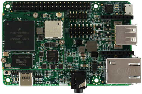
Expanding the i.MX 6 series, the i.MX 6UltraLite is a high performance, ultra-efficient processor family featuring an advanced implementation of a single ARM® Cortex®-A7 core. The Pico variant is pin-compatible with the Intel® Edison for sensors and low-speed I/O, but also adds additional expansion possibilities for multimedia and connectivity, giving you cutting edge technology that can easily be expanded and implemented for IoT designs.
从 i.MX 6 系列中扩展而来,i.MX 6UltraLite 是一个高性能,非常高效的处理器系列,采用的是单个 ARM® Cortex®-A7 核。Pico 板和 Intel® Edison 板对传感器和低速 I/O 来讲是管脚兼容的,但也加了对多媒体和联网的扩展可能,这使得板子可以很容易的用到最新的 IoT 技术。
Flashing the image
烧录映像
Before you begin flashing, you will need the following items in addition to your board:
烧录前除了板子还需要下面几项:
USB-C or Micro-USB cable
USB-C 或 Micro-USB 线
5V DC power adapter (not needed for the Pico i.MX6UL board)
5V 直流适配器 ( Pico i.MX6UL 板子不需要)
To flash Android Things onto your board, download the latest preview image in the Android Things Console (see the release notes) and follow these steps:
为了烧录 Android Things 到板子上,从 Android Things Console 下载最新的映像(看下 release notes)并按以下步骤来做:
Step 1: Connect the Hardware
Step 1: 连上硬件
Connect the board to your host computer:
连接板子到主机:
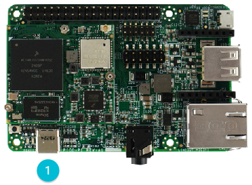
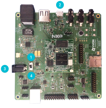
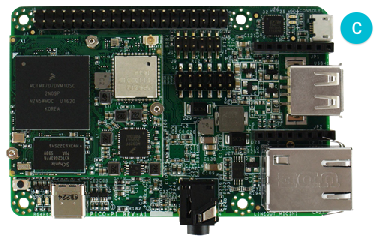
For Pico i.MX6UL:
对于 Pico i.MX6UL 板:
Connect a USB-C cable from your host computer to the USB OTG connector.
把板子上的 USB OTG 接口和主机之间用 USB-C 线连起来。
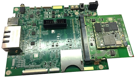
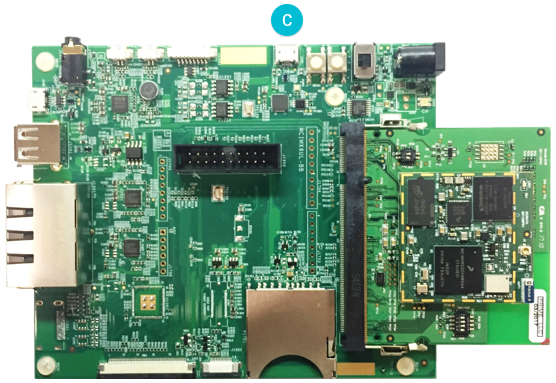
For SprIoT i.MX6UL:
对于 SprIoT i.MX6UL 板:
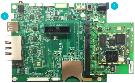
Connect a Micro-USB cable to the USB OTG connector.
把板子上的USB OTG接口和主机之间用 USB-C线连起来。
Connect a 5V power adapter to the power input connector.
连一个5V 电源适配器到电源输入接口
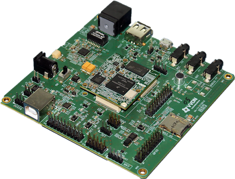
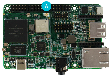
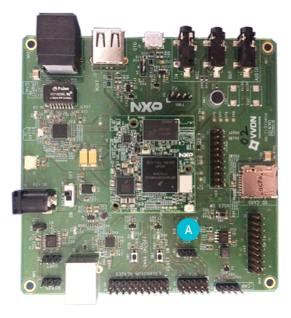
For Argon i.MX6UL:
对于 Argon i.MX6UL 板:
Ensure switch SW1 is in the OFF position.
确保开关 SW1 保持在 关 。
Connect a Micro-USB cable to the OTG (J7) connector.
用 Micro-USB 线连到 OTG (J7) 接口。
Connect a 5V power adapter to the power input (J2) connector.
用5V电源适配器连电源输入接口(J2)。
Move SW1 to the ON position to power the board.
把 SW1 切换到 开 给板子上电。
Step 2: Flash Android Things
第二步:烧录 Anroid Things
Use the following steps to flash the Android image:
使用下面步骤来烧录 Android 映像:
Download and install Android Studio or the
sdkmanagercommand-line tool. Update the Android SDK Platform Tools to version 25.0.3 or later from the SDK Manager.下载并安装 Android Studio 或者安装
sdkmanager命令行工具。从 SDK Manager更新 Android SDK Platform Tools 到 25.0.3 版或更新版本。
Navigate to the Android SDK location on your computer; the path can be found in the system settings for Android Studio. Verify that the
fastbootbinary is installed in theplatform-tools/directory.找到您电脑上的 Android SDK 的位置; 路径可以在Android Studio的设置里面找到。确认
fastboot在platform-tools/目录里。After you have the fastboot tool, add it to your
PATHenvironment variable. This command should be similar to the following:如果已经装了fastboot, 加到
PATH环境变量里面。命令如同如下:
`export PATH=$PATH:"path/to/fastboot"`
Open a command line terminal and navigate to the unzipped image directory.
打开一个命令行终端并切换到映像的解压目录。
Verify that the device has booted into Fastboot mode by executing the following command:
为了验证板子已经进入了 fastboot 模式,可以执行以下命令:
$ fastboot devices1b2f21d4e1fe0129 fastboot
Note: Your device will not boot into Fastboot mode if it was previously flashed with Android Things. You need to first execute the following command using the adb tool to reboot the device into Fastboot mode.
注意: 如果前面已经烧了 Android Things 映像,板子会进入不了 fastboot 模式。 这样就需要用 adb tool 执行下面命令使得板子进入 fastboot 模式。
$ adb reboot bootloader
Execute the
flash-all.shscript. This script installs the necessary bootloader, baseband firmware(s), and operating system. (On Windows systems, useflash-all.batinstead).执行
flash-all.sh脚本。 此脚本会安装 bootloader、基带固件、和操作系统(如在 Windows 系统上,请替换为flash-all.bat脚本)。
Note: The device automatically reboots into Android Things when the process is complete.
注意: 当处理程序结束会自动启动到 Android Things 。
To verify that Android is running on the device, discover it using the adb tool:
为了验证 Android 正在板子上运行,可以用 adb tool执行如下命令:
$ adb wait-for-device…$ adb devicesList of devices attached1b2f21d4e1fe0129 device
Connecting Wi-Fi
连接 Wi-Fi
After flashing your board, it is strongly recommended to connect it to the internet. This allows your device to deliver crash reports and receive updates.
在板子烧过后,强烈建议要连上网。这样您的设备就能上传崩溃报告并及时收到更新。
Note: The device doesn’t need to be on the same network as your computer.
注意: 板子不需要和您的主机在一个网络上。
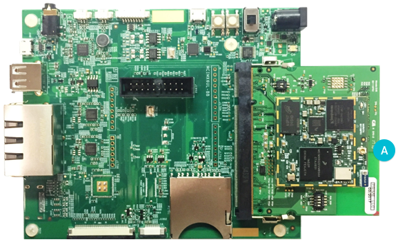
Before connecting your board to a Wi-Fi network, attach an external IPEX or u.FL Wi-Fi antenna to your board as shown:
在连到 Wi-Fi 之前, 连一根 IPEX 或者 u.FL Wi-Fi 天线到板子上如下所示:
For Pico i.MX6UL:
对于 Pico i.MX6UL 板:
For SprIoT i.MX6UL
对于 SprIoT i.MX6UL 板:
对于 Argon i.MX6UL板:
Note: The module can’t resolve Wi-Fi signals if you proceed without connecting an antenna.
注意: 如果不连接天线模块无法处理 Wi-Fi信号。
To connect your board to Wi-Fi, first access a shell prompt on the device. You can use either of the following methods:
为了连板子到 Wi-Fi,先连上板子的 shell 终端。可以使用下面任意一种方法:
Open a shell over adb with the
adb shellcommand.用 adb 命令
adb shell打开一个 shell 终端。Connect to the serial console.
连 串口。
Once you can access a shell prompt, follow these steps:
一旦连到一个 shell 终端, 按下面步骤来:
Send an intent to the Wi-Fi service that includes the SSID of your local network. Your board must support the network protocol and frequency band of the wireless network in order to establish a connection.
向 Wi-Fi 服务发送带有您的本地网络 SSID 的请求。您的 开发板 必须支持无线网络协定和无线网络频率以建立连接。
$ am startservice \ -n com.google.wifisetup/.WifiSetupService \ -a WifiSetupService.Connect
The following arguments are supported with this command:
此命令支持以下参数:
| Argument 参数 | Description 具体细节 |
|---|---|
-e ssid <var>network_ssid</var> |
Connect to the wireless network SSID specified by networkssid. _This argument is required. 连接到由 network_ssid 指定的无线网络 SSID 。此参数为必须参数 |
-e passphrase <var>network_pass</var> |
Optional argument to use the passcode specified by network_pass to connect to the network SSID. This argument is not necessary if your network doesn’t require a passcode. 可选操作,通过 network_pass 指定的密码来连接网络 SSID 。不必要操作如果您的网络不需要密码。 |
-e passphrase64 <var>encoded_pass</var> |
Optional argument used in place of passphrase for passcodes with special characters (space, !, ", $, &, ', (, ), ;, <, >,, or |). Use [base64 encoding](https://www.base64encode.org/) to specify the value for <var>encoded_pass</var>.
可选操作,设置密码passphrase可用特殊字符 (space, !, “, $, &, ‘, (, ), ;, <, >, , or |)。使用 base64 encoding 来指定 encoded_pass 的值 |
--ez hidden true |
Optional argument to indicate that the SSID specified in this command is hidden. If omitted, this value defaults to false. 可选操作,用来表明此命令中的 SSID 不可见。如果省略,此值会被默认为 false |
Verify that the connection was successful through
logcat:通过
logcat确认连接成功:$ logcat -d | grep Wifi...V WifiWatcher: Network state changed to CONNECTEDV WifiWatcher: SSID changed: ...I WifiConfigurator: Successfully connected to ...
Test that you can access a remote IP address:
测试您可以访问远程 IP 地址:
$ ping 8.8.8.8PING 8.8.8.8 (8.8.8.8) 56(84) bytes of data.64 bytes from 8.8.8.8: icmp_seq=1 ttl=57 time=6.67 ms64 bytes from 8.8.8.8: icmp_seq=2 ttl=57 time=55.5 ms64 bytes from 8.8.8.8: icmp_seq=3 ttl=57 time=23.0 ms64 bytes from 8.8.8.8: icmp_seq=4 ttl=57 time=245 ms
Check that the date and time are set correctly on the device:
确认设备上的日期与时间设置正确:
$ date
Note: An incorrect date or time may cause SSL errors. Restart the device to automatically set the correct date and time from a time server.
注意 不正确的日期或者时间可能造成 SSL 错误。重启设备从服务器自动获取正确的日期和时间。
If you want to clear all of the saved networks on the board:
如果您要清空开发板上所有已存的网络,可使用以下命令:
$ am startservice \ -n com.google.wifisetup/.WifiSetupService \ -a WifiSetupService.Reset
Serial debug console
调试串口
The serial console is a helpful tool for debugging your board and reviewing system log information. The console is the default output location for kernel log messages (i.e. dmesg), and it also provides access to a full shell prompt that you can use to access commands such as logcat. This is helpful if you are unable to access ADB on your board through other means and have not yet enabled a network connection.
串口是很有用的调试板子看系统打印信息的工具。串口是内核打印信息的缺省输出口(例如 dmesg),串口能提供一个完全的命令行终端来执行类似 logcat的命令。如果此时板子不能用 ADB 命令来访问同时也不能联网时特别有用。
To access the serial console:
连接串口:
For Pico i.MX6UL: Connect a micro USB cable to the debug interface as shown below.
对 Pico i.MX6UL板: 如下图,连 micro USB 线到调试接口上。
For SprIoT i.MX6UL: Connect a Micro-USB cable to the board as shown below.
对 SprIoT i.MX6UL 板: 如下图,把 Micro-USB 线连到板子上。
For Argon i.MX6UL: Connect a USB Type B cable to the board as shown below.
对 Argon i.MX6UL板: 如下图,把 USB Type B 线连到板子上。

Open a connection to the USB serial device on your development computer using a terminal program, such as PuTTY (Windows), Serial (Mac OS), or Minicom (Linux). The serial port parameters for the console are as follows:
使用串口终端程序在您的 PC 上打开 USB 串口设备, 例如 PuTTY(Windows下),串口(Mac 下),或者 Minicom(Linux下)。串口的参数设置如下:
Baud Rate: 115200
比特率:115200
Data Bits: 8
数据位:8
Parity: None
奇偶校验:无
Stop Bits: 1
停止位:1

若有收获,就点个赞吧
0 人点赞
