在我们的相机已经变得非常智能之后,是时候应该暂时休息一下了,我们用一个通过本渲染器能得到的最漂亮最梦幻的场景来为我们的初级阶段内容画上一个完美的句号。
在这之前还有一件事情要做,我们的相机太过完美,以至于现实世界中的相机有的缺点他都没有。为了我们能得到更真实的场景,我们甚至不得不想方设法模仿现实相机的某些特点。
传统相机的局限
现实中的相机可无法把它获取的所有光线都汇聚到一点,通过我们的逆光路模型来解释,就是它无法精准的控制发射光线的起点都重合在一起。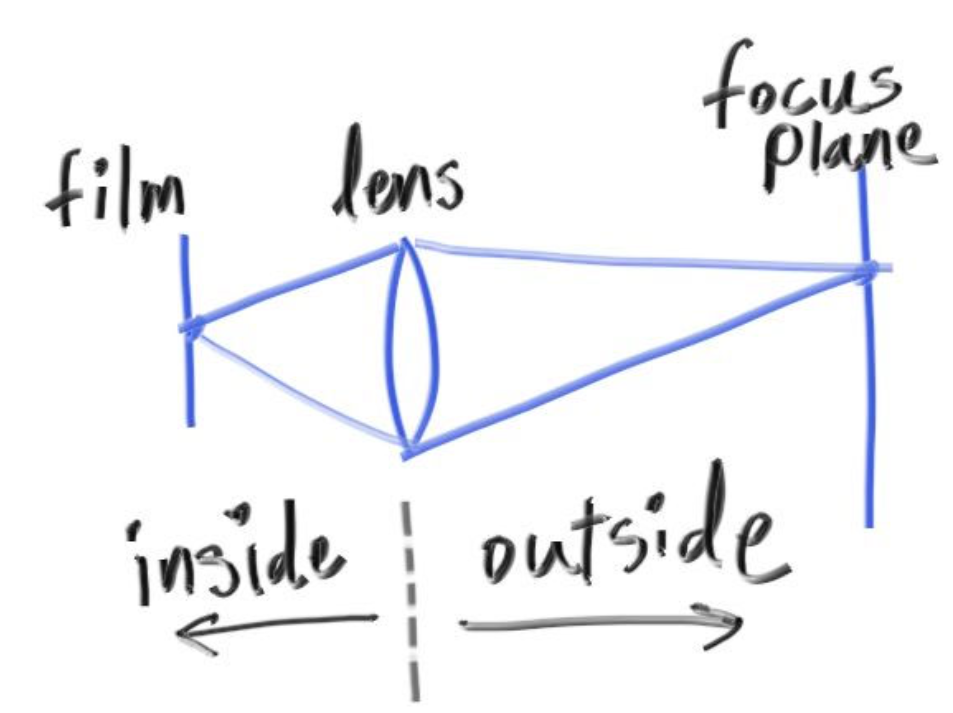
如上图所示,inside表示相机内部,outside是相机的外部。
相机通过镜头采集光线,镜头采集到的光线会被汇总,在镜头后的胶片上成像。在镜头之外,根据镜头凹透镜的焦距,在某个距离处采集到的光线都来自于一点,这个平面上的所有物体都处于完美对焦状态,而其他距离下的物体,都会因为光线无法精准落于一点而出现模糊。离完美对焦距离越远,就越模糊。
模拟相机散焦模糊效果
我们不需要模拟相机的内部,在《抗锯齿》那一章我们编写的多采样求平均的算法就可以完美模拟从镜头采集到成像的过程,现在,我们只需要改变我们光线的发射位置,假装我们的光线是从镜头上任意一点发射的即可。
具体要怎么做呢?
1.我们要如何模拟镜头呢?
我们可以以原来的固定光线发射点为圆心,找一个圆片,这个圆片和虚拟视口所在平面平行,和相机正对方向垂直。然后我们在这个圆片上随机找一个点,以这个点为起点发射光线(这个圆片就是虚拟相机的镜头)。这个圆片的大小对应着真实相机中的镜头光圈大小,圆片越大,散焦模糊效果就越大。
2.我们要如何模拟光线聚焦效果呢?
我们的光线是射向虚拟视口上的虚拟像素内的。在我们原来的设计里,虚拟视口和相机位置的距离始终为1,这意味着,我们的光线都会在镜头前方距离为1的平面上聚焦,如果我们需要让他能在任意位置聚焦,我们只需要改变虚拟视口距离相机的距离即可。
还记得我们是如何在代码中规定虚拟视口的位置的吗?lower_left_corner = origin - horizontal/2 - vertical/2 - w;
如果我想把它推到和相机位置距离为2的平面上,我仅仅是修改w的系数就可以了吗?比如:~~ lower_left_corner = origin - horizontal/2 - vertical/2 - 2*w; ~~
这样就足够了吗?不行,看下图: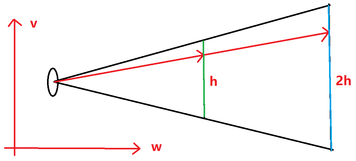
图上描绘的是相机空间下VoW面上的截面,假设中间的绿色竖线就是原先的虚拟视口,它离相机的距离为1,现在我们要把它移动到右边的蓝色平面上,根据相似三角形,如果它离相机的距离改成2,那他的高度会同步扩大为2,且因为像素数量没变,每个虚拟像素的大小也会增加为2。这意味着我们的horizontal和vertical也得同步进行放大。
图中射向虚拟视口的光线假设命中了第x行,如果像素的大小扩大两倍,这根光线的延长线也会命中蓝色视口的第x行。如果像素没有放大,它将命中第2x行,这就不对了。
明白了以上两点,我们就可以开始写代码了。
更改相机代码,现在我们可以传入焦距和光圈大小:
class camera {public:camera(point3 lookfrom,point3 lookat,vec3 vup,double vfov,double aspect_ratio,//光圈直径double aperture,//焦距double focus_dist) {auto theta = degrees_to_radians(vfov);auto h = tan(theta/2);auto viewport_height = 2.0 * h;auto viewport_width = aspect_ratio * viewport_height;w = unit_vector(lookfrom - lookat);u = unit_vector(cross(vup, w));v = cross(w, u);origin = lookfrom;//我们要把虚拟视口推到离相机位置有focus_dist的距离的平面上。//原本的距离是1,距离变成原来的focus_dist倍。//所以,horizontal和vertical得同步乘以focus_dist倍。horizontal = focus_dist * viewport_width * u;vertical = focus_dist * viewport_height * v;//距离不再是w,而是focus_dist*w。lower_left_corner = origin - horizontal/2 - vertical/2 - focus_dist*w;//处理一下,拿到半径。lens_radius = aperture / 2;}ray get_ray(double s, double t) const {// 生成一个偏移值。// 这个random_in_unit_disk()函数会产生一个XoY平面上的以原点为圆心的单位圆片内随机一点。// 该函数我们之后给出。vec3 rd = lens_radius * random_in_unit_disk();// 把圆片从XoY平面,调整到uv平面上。这段结合后面给出的random_in_unit_disk函数一起看效果最佳。vec3 offset = u * rd.x() + v * rd.y();return ray(// 顶点加上偏移。origin + offset,// -offset使得光线还是朝虚拟视口上的当前像素上发射的。lower_left_corner + s*horizontal + t*vertical - origin - offset);}private:point3 origin;point3 lower_left_corner;vec3 horizontal;vec3 vertical;vec3 u, v, w;double lens_radius;};
把random_in_unit_disk函数写在vec3.h类的类外,这个函数负责生成一个XoY面上以原点为圆心的圆片内的随机一点:
//XoY面上以原点为圆心的圆片内的随机一点。vec3 random_in_unit_disk() {while (true) {auto p = vec3(random_double(-1,1), random_double(-1,1), 0);if (p.length_squared() >= 1) continue;return p;}}
我们还是使用上一章的场景,但我们要调整相机,给一个很大的光圈直径,并且把对焦平面(虚拟视口)放在画面正中心的小球上:
point3 lookfrom(3,3,2);point3 lookat(0,0,-1);vec3 vup(0,1,0);auto dist_to_focus = (lookfrom-lookat).length();auto aperture = 2.0;camera cam(lookfrom, lookat, vup, 20, aspect_ratio, aperture, dist_to_focus);
你会得到这张图,我们的光圈很大,只要物体离虚拟视口有一点距离,就看不清了。<br />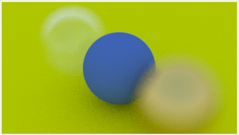
《蓝天下的我们》
我们现在来汇总我们在这十五篇文章中学到的所有知识,绘制一张图片,这将会是集大成之作,看代码:
// 这个函数帮助生成一个丰富多彩的场景!!!hittable_list random_scene() {hittable_list world;auto ground_material = make_shared<lambertian>(color(0.5, 0.5, 0.5));//先来一个“地板”,它比我们之前创建过最大的球还要大十倍!!!world.add(make_shared<sphere>(point3(0,-1000,0), 1000, ground_material));//在这个循环里我们将生成数个小球!!!for (int a = -11; a < 11; a++) {for (int b = -11; b < 11; b++) {//先进行一次随机采样,这次采样用来决定本轮循环生成的小球的材质!!!auto choose_mat = random_double();//在一个y=0.2这个平面上的一块方形区域里随机找一个点,作为这颗小球的球心!!!point3 center(a + 0.9*random_double(), 0.2, b + 0.9*random_double());//我们腾出一个位置,让生成的这些小球离(4, 0.2, 0)这个点远一点!!!//因为这里我们要放置一个非常明显的大球,如果出现球与球重合就会影响美观了!!!if ((center - point3(4, 0.2, 0)).length() > 0.9) {//定义一个智能指针,但先别急着决定指向什么类型的材质对象!!!shared_ptr<material> sphere_material;if (choose_mat < 0.8) {//我们的材质有百分之八十的概率会是磨砂材质。auto albedo = color::random() * color::random();sphere_material = make_shared<lambertian>(albedo);world.add(make_shared<sphere>(center, 0.2, sphere_material));}else if (choose_mat < 0.95) {//我们的材质有百分之十五的概率会是金属材质。auto albedo = color::random(0.5, 1);auto fuzz = random_double(0, 0.5);sphere_material = make_shared<metal>(albedo, fuzz);world.add(make_shared<sphere>(center, 0.2, sphere_material));} else {//我们的材质有百分之五的概率会是玻璃材质。sphere_material = make_shared<dielectric>(1.5);world.add(make_shared<sphere>(center, 0.2, sphere_material));}}}}//三颗站在C位的大球!!!auto material1 = make_shared<dielectric>(1.5);world.add(make_shared<sphere>(point3(0, 1, 0), 1.0, material1));auto material2 = make_shared<lambertian>(color(0.4, 0.2, 0.1));world.add(make_shared<sphere>(point3(-4, 1, 0), 1.0, material2));auto material3 = make_shared<metal>(color(0.7, 0.6, 0.5), 0.0);world.add(make_shared<sphere>(point3(4, 1, 0), 1.0, material3));return world;}int main() {//调整图片参数const auto aspect_ratio = 3.0 / 2.0;//分辨率调高点,玩票大的!!!const int image_width = 1200;const int image_height = static_cast<int>(image_width / aspect_ratio);//拉高采样率会增加最终艺术品的成色!!!const int samples_per_pixel = 500;const int max_depth = 50;//调用函数生成一个有着许多随机小球的场景!!!auto world = random_scene();// 放置相机point3 lookfrom(13,2,3);point3 lookat(0,0,0);vec3 vup(0,1,0);auto dist_to_focus = 10.0;//这次是小光圈。auto aperture = 0.1;camera cam(lookfrom, lookat, vup, 20, aspect_ratio, aperture, dist_to_focus);// renderloopstd::cout << "P3\n" << image_width << ' ' << image_height << "\n255\n";for (int j = image_height-1; j >= 0; --j) {...}
你会得到:<br />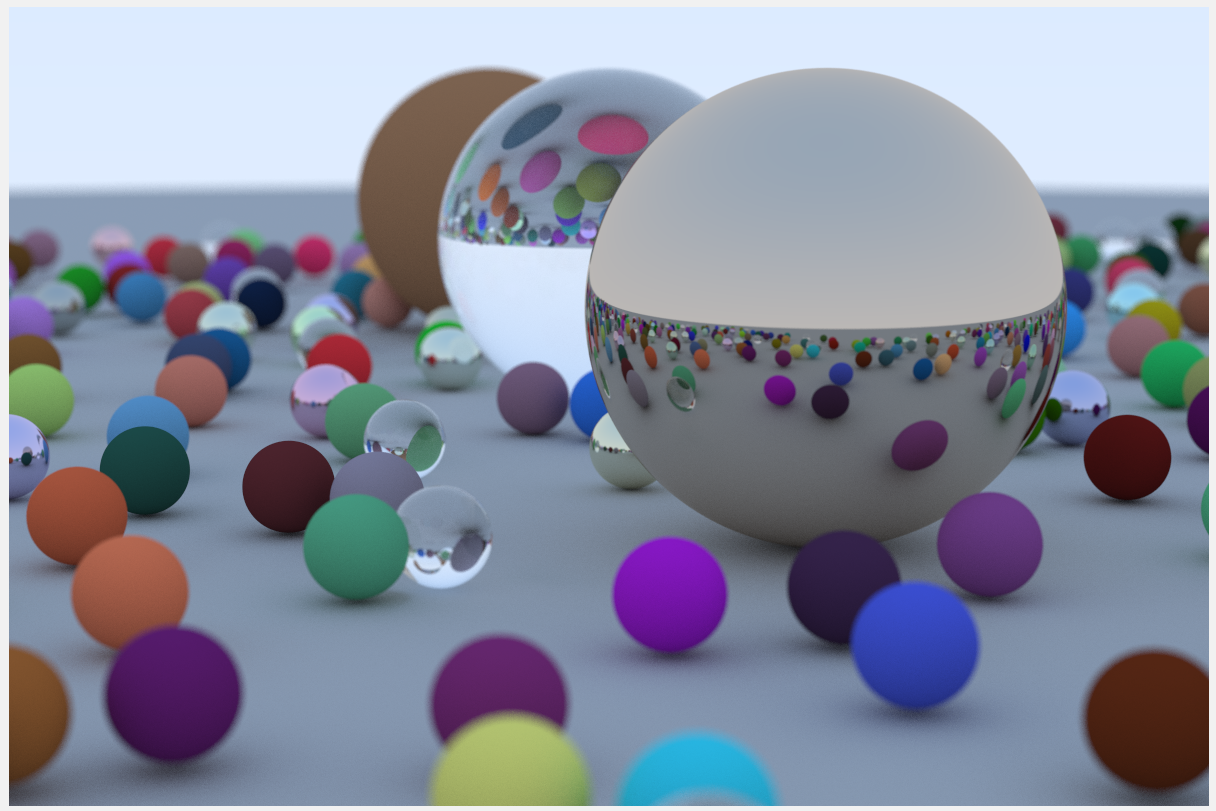<br />你可以给你的随机数生成器其他的种子,来改变小球的随机位置,直到你得到满意的结果。
参考文献
https://raytracing.github.io/books/RayTracingInOneWeekend.html
参考自《RayTracingInOneWeekend》第12节。

若有收获,就点个赞吧
0 人点赞
