第二期视频回放
第二期代码及课件下载地址
第二期直播内容文字版
本期主要介绍了以下十几种元素的创建方法,您可以使用上方的链接直接下载工程,打开工程文件后若您的MicroStation安装在默认路径中,则可以直接编译,使用定义的命令查看效果以供学习。若您的MicroStation软件未安装在默认路径,则您可以参考以下文章,修改路径后即可正确运行。<br />[零基础怎么学MicroStation的二次开发](https://www.yuque.com/docs/share/19180260-82e2-4e6a-be60-5bbc87569b32?# 《零基础怎么学MicroStation的二次开发》)<br />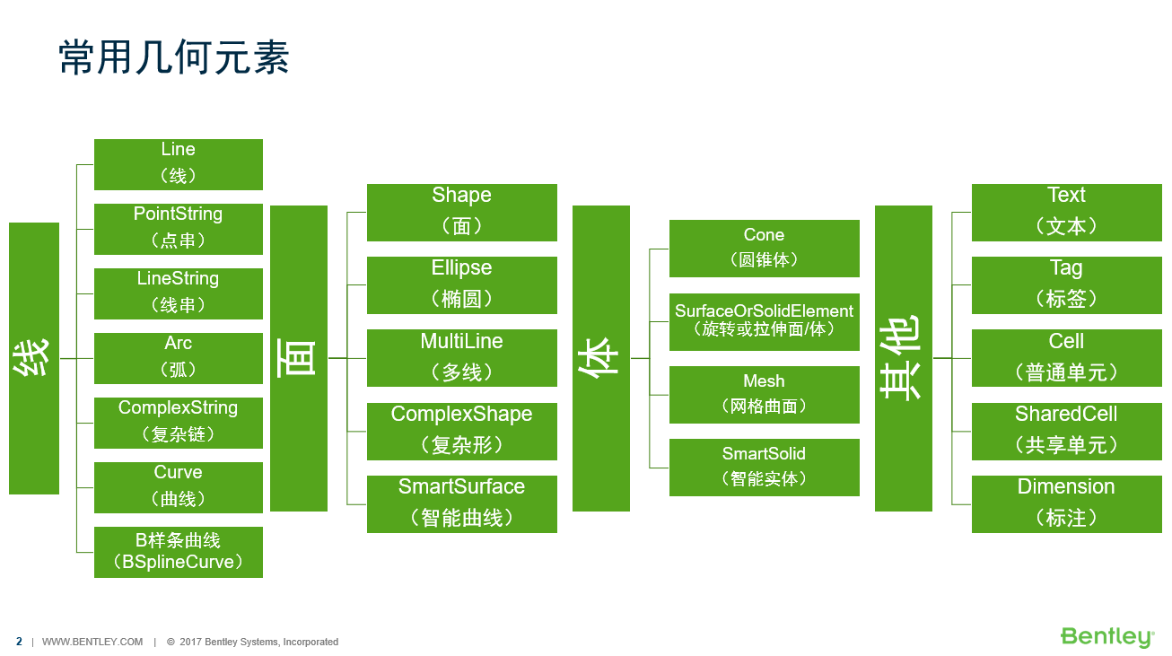<br />**图1 本次课程介绍元素一览**
线
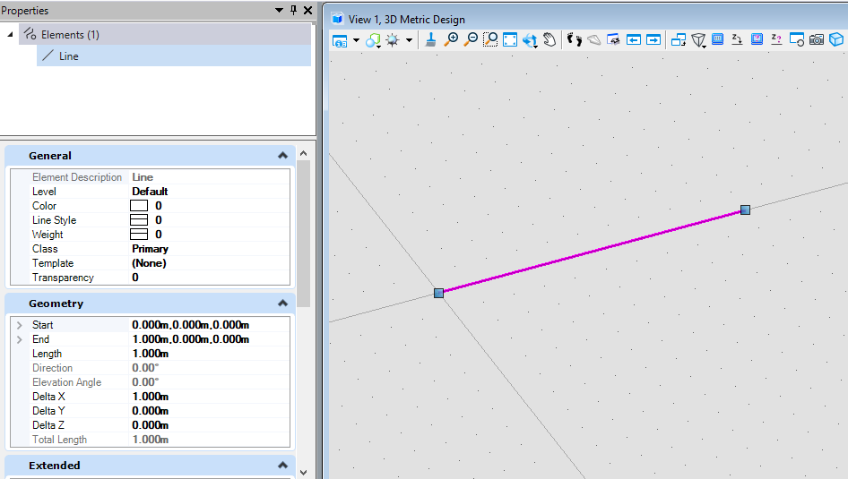
线元素(LineElement)
该创建方式为首先创建坐标,然后使用坐标创建直线几何,再使用直线几何创建直线元素。
public static void CmdCreateLine(string unparsed){DgnModel dgnModel = Session.Instance.GetActiveDgnModel();//获取当前的模型空间DPoint3d p1 = DPoint3d.Zero;//定义三维点DPoint3d p2 = new DPoint3d(10000, 0, 0);DSegment3d segment = new DSegment3d(p1, p2);//定义直线图元LineElement line = new LineElement(dgnModel, null, segment);//定义直线元素line.AddToModel();//将直线元素写入模型空间}
点串元素(PointStringElement)
第一种创建点串的方法为首先创建一个用于存储点串坐标点的数组,然后使用这个数组创建点串元素。
public static void CmdCreatePointString1(string unparsed){DgnModel dgnModel = Session.Instance.GetActiveDgnModel();//获取当前的模型空间DPoint3d p1 = DPoint3d.Zero;//定义三维点DPoint3d p2 = new DPoint3d(10000, 10000, 0);DPoint3d p3 = new DPoint3d(20000, 0, 0);DPoint3d p4 = new DPoint3d(30000, -10000, 0);DPoint3d p5 = new DPoint3d(40000, 0, 0);DPoint3d[] pos = { p1, p2, p3, p4, p5 };//将三维点添加到三维点数组中PointStringElement pointString = new PointStringElement(dgnModel, null, pos, true);//定义点串pointString.AddToModel();//将点串元素写入模型空间}
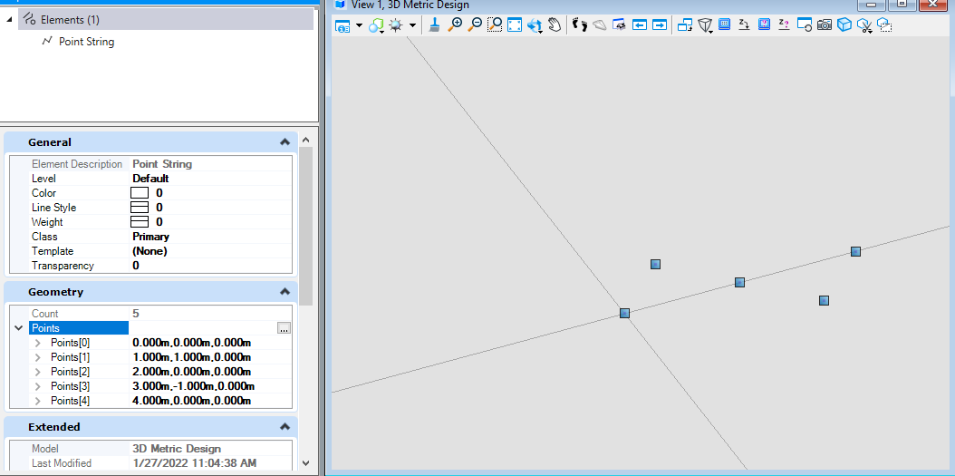
图3 绘制结果
第二种创建点串的方法为首先创建一个用于存储点串坐标点的数组,同时可以使用变换矩阵对点坐标位置进行修改,最后使用这个数组创建点串元素。
public static void CmdCreatePointString2(string unparsed){DgnModel dgnModel = Session.Instance.GetActiveDgnModel();//获取当前的模型空间DPoint3d p1 = DPoint3d.Zero;//定义三维点DPoint3d p2 = new DPoint3d(10000, 10000, 0);DPoint3d p3 = new DPoint3d(20000, 0, 0);DPoint3d p4 = new DPoint3d(30000, -10000, 0);DPoint3d p5 = new DPoint3d(40000, 0, 0);DPoint3d[] pos = { p1, p2, p3, p4, p5 };//将三维点添加到三维点数组中DMatrix3d m1 = DMatrix3d.Identity;//定义变换矩阵DMatrix3d m2 = DMatrix3d.Identity;DMatrix3d m3 = DMatrix3d.Identity;DMatrix3d m4 = DMatrix3d.Identity;DMatrix3d m5 = DMatrix3d.Identity;DMatrix3d[] ms = { m1, m2, m3, m4, m5 };//将变换矩阵添加到变换矩阵数组中PointStringElement pointString = new PointStringElement(dgnModel, null, pos, ms, true);//定义点串pointString.AddToModel();//将点串元素写入模型空间}

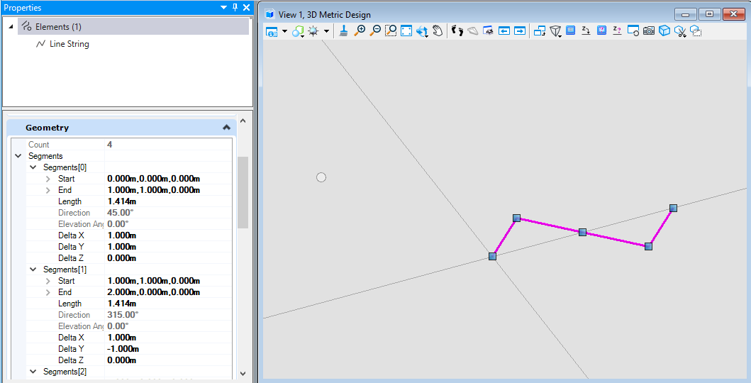
线串元素(LineStringElement)
线串元素的创建方法为首先创建用于储存线串元素端点的坐标数组,然后使用这个数组创建线串元素。
public static void CmdCreateLineString(string unparsed){DgnModel dgnModel = Session.Instance.GetActiveDgnModel();//获取当前的模型空间DPoint3d p1 = DPoint3d.Zero;//定义三维点DPoint3d p2 = new DPoint3d(10000, 10000, 0);DPoint3d p3 = new DPoint3d(20000, 0, 0);DPoint3d p4 = new DPoint3d(30000, -10000, 0);DPoint3d p5 = new DPoint3d(40000, 0, 0);DPoint3d[] pos = { p1, p2, p3, p4, p5 };//将三维点添加到三维点数组中LineStringElement lineString = new LineStringElement(dgnModel,null,pos);//定义线串元素lineString.AddToModel();//将线串元素写入模型空间}
弧元素(ArcElement)
第一种弧元素的创建方式是首先使用定义的圆心,长轴矢量与短轴矢量,构建出几何椭圆,然后利用定义的几何椭圆定义弧元素。
public static void CmdCreateArc1(string unparsed){DgnModel dgnModel = Session.Instance.GetActiveDgnModel();//获取当前的模型空间DPoint3d centerPo = DPoint3d.Zero;//定义圆心DVector3d vector0 = new DVector3d(0, 20000, 0);//定义长轴矢量DVector3d vector90 = new DVector3d(-10000, 0, 0);//定义短轴矢量DEllipse3d ellipse = new DEllipse3d(centerPo, vector0, vector90);//定义几何椭圆ArcElement arc = new ArcElement(dgnModel, null, ellipse);//使用几何椭圆定义弧元素arc.AddToModel();//将弧元素写入模型空间}
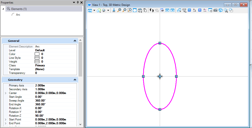
图6 绘制结果
第二种弧元素的创建方式是使用定义圆心坐标,设定弧元素的主轴长,副轴长,旋转角,起始旋转角,扫掠角属性参数创建弧元素。
public static void CmdCreateArc2(string unparsed){DgnModel dgnModel = Session.Instance.GetActiveDgnModel();//获取当前的模型空间DPoint3d centerPo = DPoint3d.Zero;//定义圆心ArcElement arc = new ArcElement(dgnModel, null, DPoint3d.Zero, 50000, 50000, 0, Angle.PI.Radians / 2, Angle.PI.Radians / 2);//使用几何椭圆定义弧元素/** 定义弧元素* dgnModel:定义弧元素所在模型空间* templateElement:元素模板* center:弧元素的圆心* axis1:主轴长* axis2:副轴长* rotation:圆弧旋转角* start:圆弧起始旋转角* sweep:圆弧扫掠角*/arc.AddToModel();//将弧元素写入模型空间}
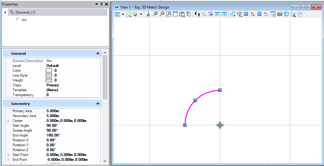
图7 绘制结果
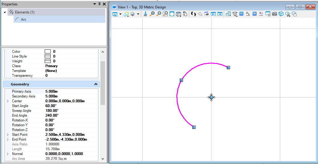
第二种弧元素的创建方式是使用定义圆心坐标,设定弧元素的主轴长,副轴长,圆弧变换矩阵(圆弧旋转角),起始旋转角,扫掠角属性参数创建弧元素。
public static void CmdCreateArc3(string unparsed){DgnModel dgnModel = Session.Instance.GetActiveDgnModel();//获取当前的模型空间DPoint3d centerPo = DPoint3d.Zero;//定义圆心DMatrix3d matrix = DMatrix3d.Identity;//定义变换矩阵ArcElement arc = new ArcElement(dgnModel, null, centerPo, 50000, 50000, DMatrix3d.Identity, Angle.PI.Radians / 3, Angle.PI.Radians);/** 定义弧元素* dgnModel:定义弧元素所在模型空间* templateElement:元素模板* center:弧元素的圆心* axis1:主轴长* axis2:副轴长* rotation:圆弧变换矩阵(圆弧旋转角)* start:圆弧起始旋转角* sweep:圆弧扫掠角*/arc.AddToModel();//将弧元素写入模型空间}
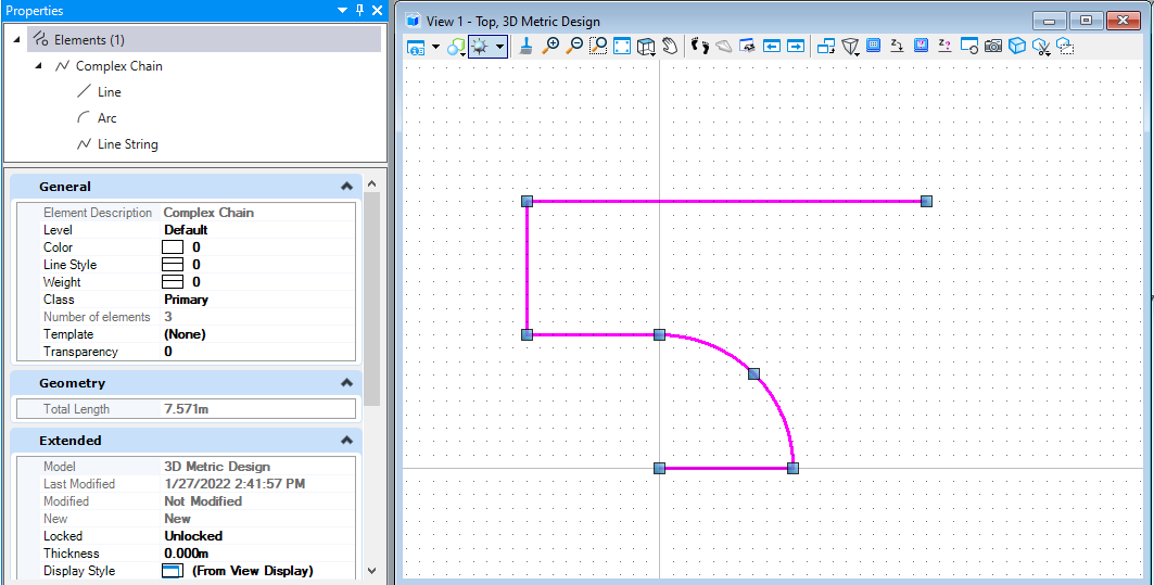
复杂形元素(ComplexStringElement)
复杂形元素是将构成元素添加到复杂形元素的子部件中,添加完成后生成。需要注意的是,复杂元素子部件构成的线形需要首尾相连,且存在顺序要求,即前者的末端连接后者的首端,否则可能会出现生成的复杂形元素不符合预期的情况。
public static void CmdCreateComplexString(string unparsed){DgnModel dgnModel = Session.Instance.GetActiveDgnModel();//获取当前的模型空间#region Create line elementDPoint3d p1 = DPoint3d.Zero;//定义三维点DPoint3d p2 = new DPoint3d(10000, 0, 0);DSegment3d segment = new DSegment3d(p1, p2);//定义直线图元LineElement line = new LineElement(dgnModel, null, segment);//定义直线元素#endregion#region Create arc elementDPoint3d centerPo = DPoint3d.Zero;//定义圆心DMatrix3d matrix = DMatrix3d.Identity;//定义变换矩阵ArcElement arc = new ArcElement(dgnModel, null, centerPo, 10000, 10000, DMatrix3d.Identity, 0, Angle.PI.Radians/2);//定义弧元素#endregion#region Create linestring elementDPoint3d p3 = new DPoint3d(0,10000,0);//定义三维点DPoint3d p4 = new DPoint3d(-10000, 10000, 0);DPoint3d p5 = new DPoint3d(-10000, 20000, 0);DPoint3d p6 = new DPoint3d(20000, 20000, 0);DPoint3d[] pos = { p3, p4, p5, p6 };//将三维点添加到三维点数组中LineStringElement lineString = new LineStringElement(dgnModel, null, pos);//定义线串元素#endregionComplexStringElement complexString = new ComplexStringElement(dgnModel, null);//定义复杂线元素complexString.AddComponentElement(line);//添加复杂线元素的子部件complexString.AddComponentElement(arc);complexString.AddComponentElement(lineString);complexString.AddComponentComplete();//添加子部件完成complexString.AddToModel();//将复杂线元素写入模型空间}
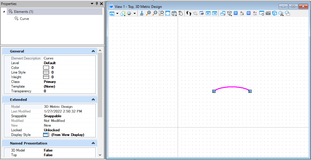
曲线元素(CurveElement)
第一种曲线元素的创建方式需要首先构建用于控制曲线轨迹的坐标点集,需要注意的是,在定义曲线元素时,点集中的坐标点个数需要大于等于6,否则无法成功创建。
public static void CmdCreateCurve1(string unparsed){DgnModel dgnModel = Session.Instance.GetActiveDgnModel();//获取当前的模型空间DPoint3d[] pos = { DPoint3d.Zero,new DPoint3d(10000, 0, 0),new DPoint3d(10000, 10000, 0),new DPoint3d(20000, 10000, 0),new DPoint3d(20000, 0, 0),new DPoint3d(30000, 0, 0)};//定义曲线控制点坐标集CurveElement curve = new CurveElement(dgnModel, null, pos);//定义曲线元素 注意:三维点个数需大于等于6curve.AddToModel();//将曲线元素写入模型空间}
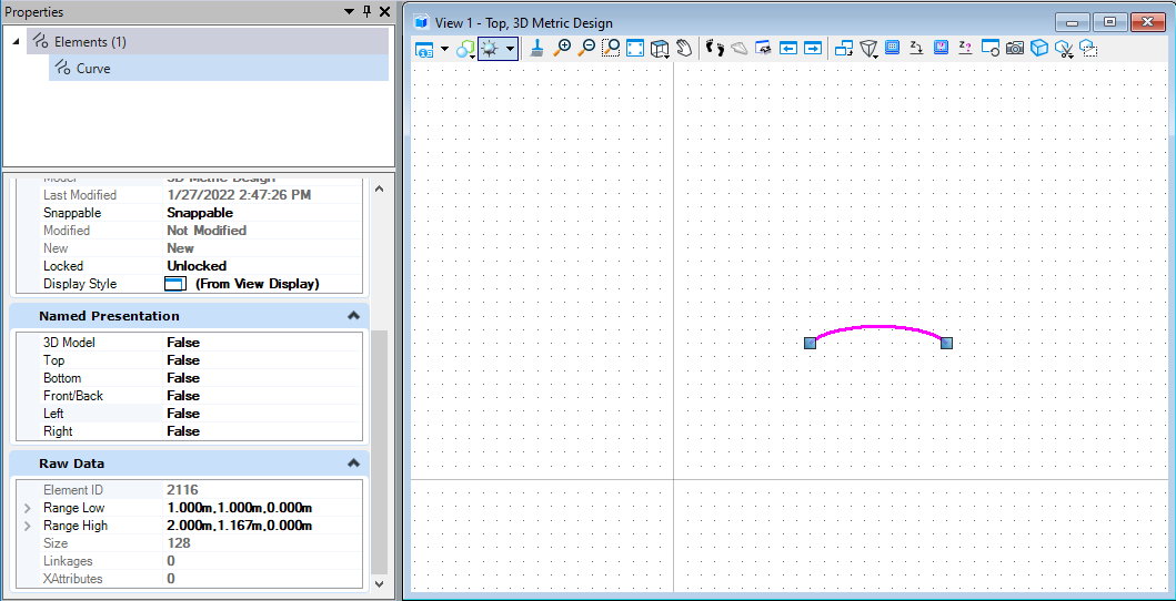
图10 绘制结果
第二种曲线元素的创建方式与上方方法的区别在于需要首先构建用于控制曲线轨迹的坐标点列表。同时坐标点数量需要大于等于6.
public static void CmdCreateCurve2(string unparsed){DgnModel dgnModel = Session.Instance.GetActiveDgnModel();//获取当前的模型空间IList<DPoint3d> pos = new List<DPoint3d>{DPoint3d.Zero,new DPoint3d(10000, 0, 0),new DPoint3d(10000, 10000, 0),new DPoint3d(20000, 10000, 0),new DPoint3d(20000, 0, 0),new DPoint3d(30000, 0, 0)};//定义曲线控制点坐标列表CurveElement curve = new CurveElement(dgnModel, null, pos);//定义曲线元素 注意:三维点个数需大于等于6curve.AddToModel();//将曲线元素写入模型空间}
B样条曲线元素(BSplineCurveElement)
第一种B样条曲线元素的创建方式是通过设置B样条曲线的控制点及起止端方向向量及MSInterpolationCurve属性后定义MSInterpolationCurve,然后通过MSInterpolationCurve创建B样条曲线元素。
public static void CmdCreateBSplineCurve1(string unparsed){DgnModel dgnModel = Session.Instance.GetActiveDgnModel();//获取当前的模型空间DPoint3d[] pts = { new DPoint3d(0, 0, 0), new DPoint3d(1000, 1000, 0), new DPoint3d(1000, -1000, 0), new DPoint3d(0, -1000, 0), new DPoint3d(0, 0, 0) };//定义B样条曲线的节点DVector3d[] tangents = { new DVector3d(0, 0), new DVector3d(0, 0) };//设置B样条曲线的起端点切线方向MSInterpolationCurve interpolationCurve = MSInterpolationCurve.CreateFromPointsAndEndTangents(pts, true, 0, tangents, true, false, false, false);/**根据节点和起端点切线方向定义插值曲线* points:插值点* removeDuplicatePoints:是否需要删除重复点* endTangents:端点切线方向向量* closedCurve:是否需要闭合曲线* colinearTangents:切线是否共线* chordLenTangents:是否仅相切弦* naturalTangents:是否为自然切线*/BSplineCurveElement bsplineCurve = new BSplineCurveElement(dgnModel, null, interpolationCurve);//用插值曲线定义B样条曲线元素bsplineCurve.AddToModel();//将B样条曲线的实例写入模型}
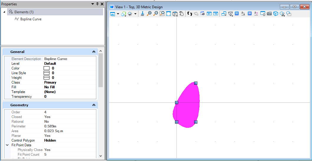
图12 绘制结果
第二种B样条曲线元素的创建方式是通过定义B样条控制线上的点创建MSBsplineCurve,然后使用MSBsplineCurve创建B样条曲线元素。关于创建MSBsplineCurve的方式有很多种,具体您可以在帮助文档中查看其他不同的创建方法。
public static void CmdCreateBSplineCurve2(string unparsed){DgnModel dgnModel = Session.Instance.GetActiveDgnModel();//获取当前的模型空间DPoint3d p1 = DPoint3d.Zero;//定义B样条曲线控制线DPoint3d p2 = new DPoint3d(10000, 10000, 0);DPoint3d p3 = new DPoint3d(20000, 0, 0);DPoint3d p4 = new DPoint3d(30000, -10000, 0);DPoint3d p5 = new DPoint3d(40000, 0, 0);DPoint3d[] pos = { p1, p2, p3, p4, p5 };//将控制点添加到控制点数组中MSBsplineCurve bsplineCurve = MSBsplineCurve.CreateFromPoints(pos);//使用控制点数组定义B样条曲线BSplineCurveElement bsplineCurveElem = new BSplineCurveElement(dgnModel, null, bsplineCurve);//用B样条曲线定义B样条曲线元素bsplineCurveElem.AddToModel();//将B样条曲线的实例写入模型}

面
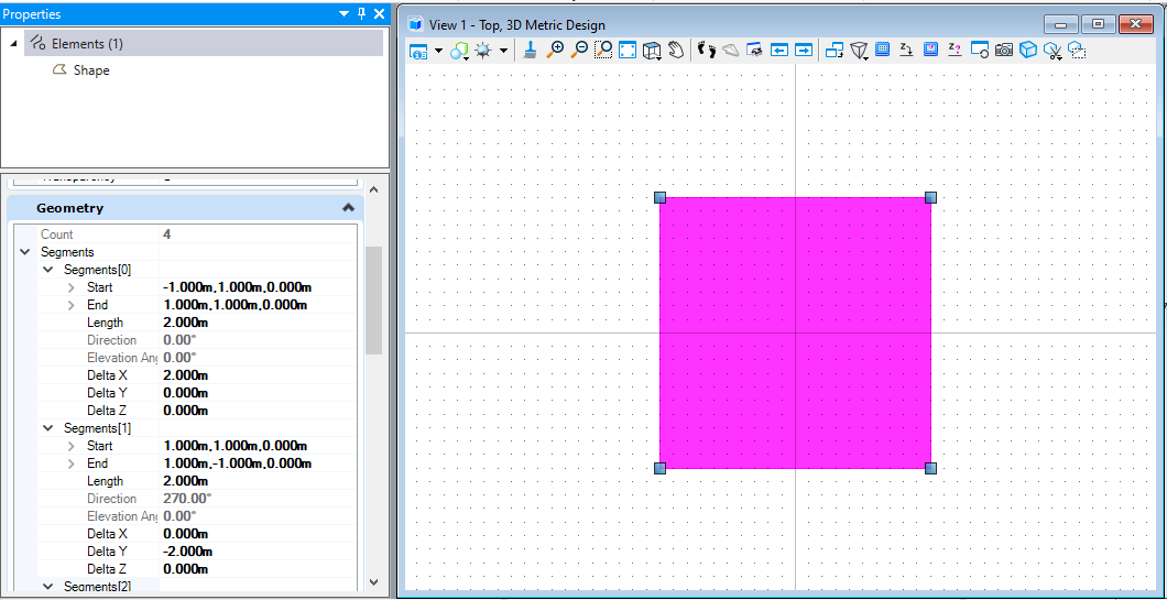
形元素(ShapeElement)
形元素的创建方式为首先定义形元素端点,而后添加到端点集中,然后使用端点集创建形元素。
public static void CmdCreateShape(string unparsed){DgnModel dgnModel = Session.Instance.GetActiveDgnModel();//获取当前的模型空间DPoint3d p1 = new DPoint3d(-10000, 10000, 0);//定义形元素端点DPoint3d p2 = new DPoint3d(10000, 10000, 0);DPoint3d p3 = new DPoint3d(10000, -10000, 0);DPoint3d p4 = new DPoint3d(-10000, -10000, 0);DPoint3d[] pos = { p1, p2, p3, p4 };//将面元素端点添加到形元素端点数组中ShapeElement shape = new ShapeElement(dgnModel,null, pos);//定义形元素shape.AddToModel();//将面元素写入模型}
椭圆元素(EllipseElement)
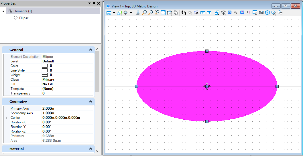
第一种创建椭圆元素的方式是通过设置椭圆的圆心,主轴及副轴向量创建椭圆几何,然后使用椭圆几何创建椭圆元素。
public static void CmdCreateEllipse1(string unparsed){DgnModel dgnModel = Session.Instance.GetActiveDgnModel();//获取当前的模型空间DPoint3d centerPo = DPoint3d.Zero;//定义圆心DVector3d vector0In = new DVector3d(20000, 0, 0);//定义主轴向量DVector3d vector90In = new DVector3d(0, 10000, 0);//定义副轴向量DEllipse3d ellipse = new DEllipse3d(centerPo, vector0In, vector90In);//定义椭圆几何EllipseElement ellipseElem = new EllipseElement(dgnModel, null, ellipse);//使用椭圆几何定义椭圆元素ellipseElem.AddToModel();}

图15 绘制结果
第二种创建椭圆元素的方法是通过设置椭圆元素中椭圆圆心,主轴长度,副轴长度及椭圆转角的方式直接创建椭圆元素。
public static void CmdCreateEllipse2(string unparsed){DgnModel dgnModel = Session.Instance.GetActiveDgnModel();//获取当前的模型空间DPoint3d centerPo = DPoint3d.Zero;//定义圆心坐标EllipseElement ellipseElem = new EllipseElement(dgnModel, null, centerPo, 20000, 10000, 45);/** 定义椭圆元素* dgnModel:写入椭圆元素的模型空间* templateElement:元素模板* center:椭圆圆心* axis1:主轴长度* axis2:副轴长度* rotation:椭圆转角*/ellipseElem.AddToModel();}
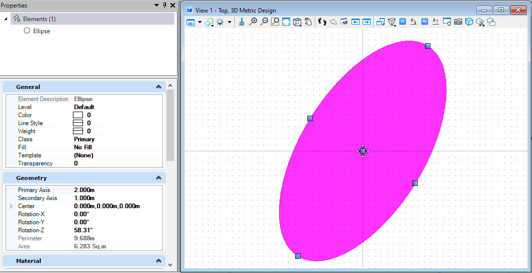
图16 绘制结果
第三种创建椭圆元素的方法是通过设置椭圆元素中椭圆圆心,主轴长度,副轴长度及椭圆变换矩阵(椭圆转角)的方式直接创建椭圆元素。
public static void CmdCreateEllipse3(string unparsed){DgnModel dgnModel = Session.Instance.GetActiveDgnModel();//获取当前的模型空间DPoint3d centerPo = DPoint3d.Zero;//定义圆心坐标EllipseElement ellipseElem = new EllipseElement(dgnModel, null, centerPo, 20000, 10000, DMatrix3d.Identity);/** 定义椭圆元素* dgnModel:写入椭圆元素的模型空间* templateElement:元素模板* center:椭圆圆心* axis1:主轴长度* axis2:副轴长度* rotation:椭圆变换矩阵(椭圆转角)*/ellipseElem.AddToModel();//将椭圆元素写入模型空间}
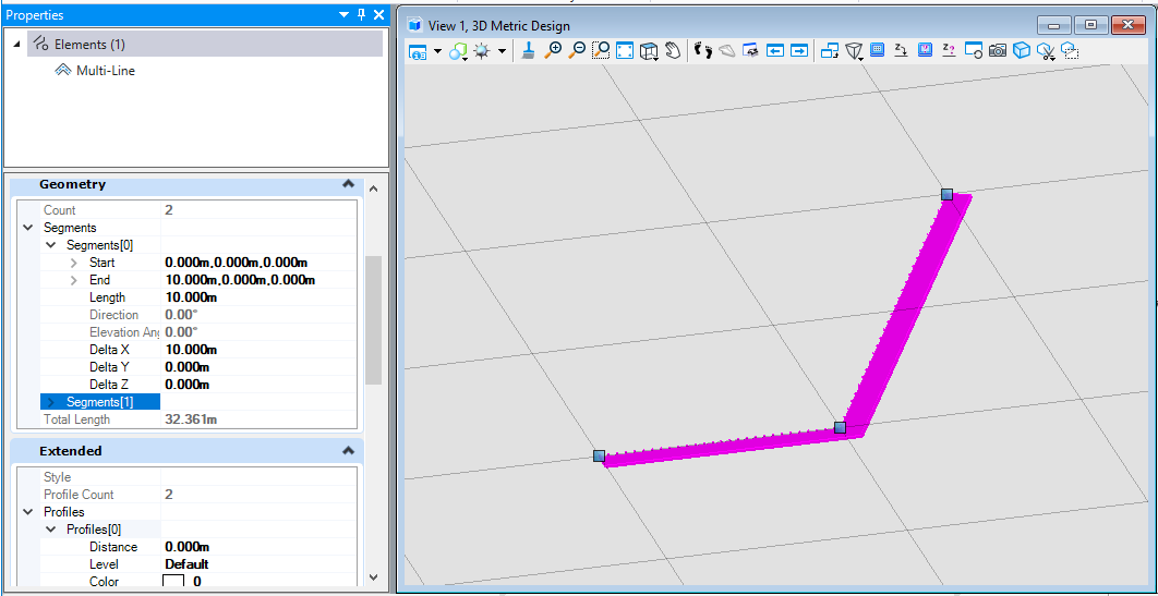
多线元素(MultilineElement)
多线元素需要首先对多线元素的轮廓进行定义,需要设置的属性主要有:轮廓的偏移值,轮廓的线样式,轮廓的偏移基点。然后对多线元素的法线方向,轨迹点进行定义,最后使用这些参数生成多线元素。
public static void CmdCreateMultiLine(string unparsed){DgnModel dgnModel = Session.Instance.GetActiveDgnModel();//获取当前的模型空间DgnFile dgnFile = Session.Instance.GetActiveDgnFile();//获取当前模型所属文件MultilineStyle lineStyle = new MultilineStyle("testMultiline",dgnFile);//定义多线元素样式MultilineProfile profile1 = new MultilineProfile();//定义多线轮廓profile1.Distance = 0;//设置轮廓偏移基点profile1.UseLinestyle = true;//设置轮廓是否使用线样式profile1.Linestyle = 1;//设置轮廓线样式lineStyle.InsertProfile(profile1, 0);//将轮廓信息写入多线样式中MultilineProfile profile2 = new MultilineProfile();//定义多线轮廓profile2.Distance = -10000;//设置轮廓偏移基点lineStyle.InsertProfile(profile2, 1);//将轮廓信息写入多线样式中DVector3d vector = DVector3d.UnitZ;//设置多线法线方向向量DPoint3d p1 = DPoint3d.Zero;//设置多线轨迹控制点DPoint3d p2 = new DPoint3d(100000,0,0);DPoint3d p3 = new DPoint3d(200000, 200000, 0);DPoint3d[] pos = { p1,p2,p3};//定义轨迹点数组MultilineElement multiline = MultilineElement.CreateMultilineElement(dgnModel,null,lineStyle,1, vector, pos);/** 定义多线元素* dgnModel:写入多线元素的模型空间* templateElement:元素模板* mlineStyle:多线样式* styleScale:样式缩放比例* normal:多线法线方向向量* points:轨迹点数组*/multiline.AddToModel();//将多线元素写入模型空间}
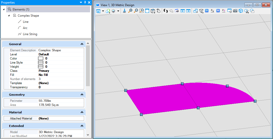
复杂形元素(ComplexShapeElement)
复杂形元素需要将构成的元素添加到复杂形元素的子部件中,添加完成后生成复杂形元素。需要注意的是,构成复杂形元素的曲线需要首尾相连,否则无法构建出预期的复杂形元素。其次在创建复杂形元素时,其子部件需要构成一个封闭的图形区域,否则程序会自动对复杂形元素进行封闭,可能会出现与预期不符的形态。
public static void CmdCreateComplexShape(string unparsed){DgnModel dgnModel = Session.Instance.GetActiveDgnModel();//获取当前的模型空间#region Create lineDPoint3d p1 = DPoint3d.Zero;//定义直线端点DPoint3d p2 = new DPoint3d(100000,0,0);DSegment3d segment = new DSegment3d(p1,p2);//定义几何直线LineElement line = new LineElement(dgnModel,null,segment);//定义直线元素#endregion#region Create arcDPoint3d centerPo = DPoint3d.Zero;//定义弧圆心点ArcElement arc = new ArcElement(dgnModel,null, centerPo,100000,100000,0,0, Angle.PI.Radians / 2);//定义弧元素#endregion#region Create linestringDPoint3d p3 = new DPoint3d(0, 100000,0);//定义线串端点DPoint3d p4 = new DPoint3d(-100000, 100000, 0);DPoint3d p5 = new DPoint3d( -100000,0, 0);DPoint3d[] pos = { p3,p4,p5,p1};//定义线串点数组LineStringElement lineString = new LineStringElement(dgnModel ,null,pos);//定义线串元素#endregionComplexShapeElement complexShape = new ComplexShapeElement(dgnModel,null);//定义复杂形元素complexShape.AddComponentElement(line);//添加子部件complexShape.AddComponentElement(arc);complexShape.AddComponentElement(lineString);complexShape.AddComponentComplete();//添加子部件完成complexShape.AddToModel();//将复杂元素写入模型}
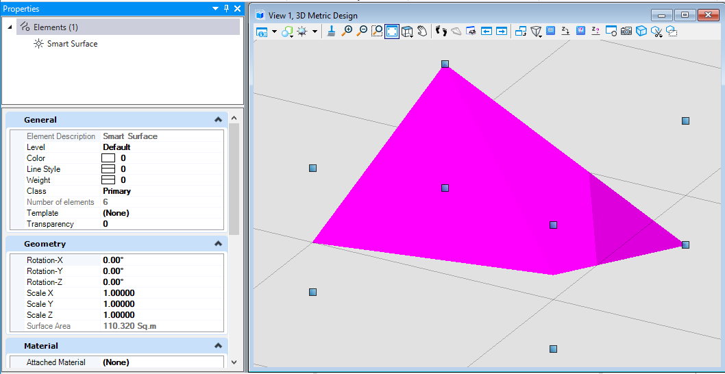
智能面(BrepCellHeaderElement)
智能面首先需要使用曲线定义出智能面的轮廓线,然后使用轮廓线生成实核实体,最后使用智能实体定义智能面。
public static void CmdSmartSurface(string unparsed){DgnModel dgnModel = Session.Instance.GetActiveDgnModel();//获取当前的模型空间DPoint3d p1 = DPoint3d.Zero;//定义曲线端点坐标DPoint3d p2 = new DPoint3d(100000, 0, 10000);DPoint3d p3 = new DPoint3d(100000, 100000, -20000);DPoint3d p4 = new DPoint3d(0, 100000, 30000);IList<DPoint3d> pos = new List<DPoint3d>() { p1, p2, p3, p4 };//将端点坐标添加到端点坐标列表中CurveVector curve = CurveVector.CreateLinear(pos, CurveVector.BoundaryType.Outer, true);//根据列表中的端点坐标定义曲线Create.BodyFromCurveVector(out SolidKernelEntity solid, curve, dgnModel);//使用曲线定义SolidEntityBrepCellHeaderElement brepCellHeader = new BrepCellHeaderElement(dgnModel, null, solid);//使用SolidEntity定义智能实体brepCellHeader.AddToModel();//将智能实体写入模型}
体
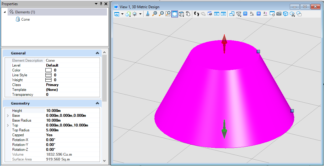
圆台(锥)元素(ConeElement)
圆台(锥)元素通过设置圆台(锥)的顶部及底部的圆心坐标,圆心半径,及旋转矩阵后创建出相应的元素。
public static void CmdCreateCone(string unparsed){DgnModel dgnModel = Session.Instance.GetActiveDgnModel();//获取当前的模型空间DPoint3d topCenter = new DPoint3d(0,0, 100000);//定义顶部圆锥(台)圆心坐标DPoint3d bottomCenter = DPoint3d.Zero;//定义底部圆锥(台)圆心坐标ConeElement cone = new ConeElement(dgnModel,null,50000,100000,topCenter,bottomCenter,DMatrix3d.Identity,true);/** 定义圆锥(台)元素* dgnModel:定义圆锥(台)元素的模型空间* templateElement:元素模板* topRadius:顶部圆锥(台)半径* bottomRadius:底部圆锥(台)半径* topCenter:顶部圆锥(台)圆心坐标* bottomCenter:底部圆锥(台)圆心坐标* rotation:应用于顶圆/底圆的旋转矩阵* isCapped:对于实体圆锥(台)来说为真*/cone.AddToModel();//将圆锥(台)写入模型}
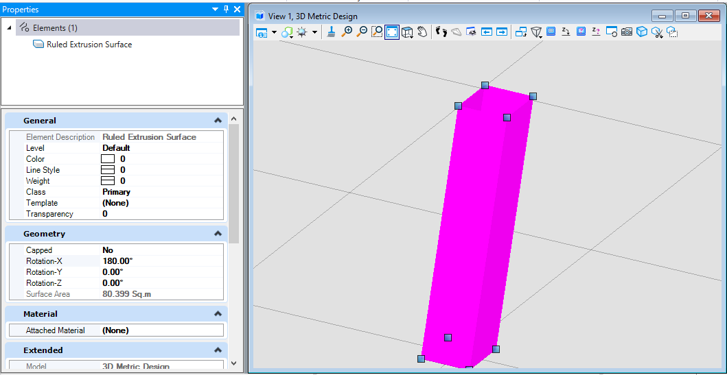
拉伸面实体(SurfaceOrSolidElement)
创建拉伸面实体时需要首先对拉伸轮廓进行定义,然后使用方向向量对拉伸体的拉伸方向,拉伸长度进行定义,最后使用这些定义的参数生成拉伸面。注意:在创建拉伸实体时,若preferSolid参数为真,则生成拉伸体,否则生成拉伸面实体。
public static void CmdCreateSurface1(string unparsed){DgnModel dgnModel = Session.Instance.GetActiveDgnModel();//获取当前的模型空间#region Create profileDPoint3d p1 = new DPoint3d(-10000, 10000, 0);//定义形元素端点DPoint3d p2 = new DPoint3d(10000, 10000, 0);DPoint3d p3 = new DPoint3d(10000, -10000, 0);DPoint3d p4 = new DPoint3d(-10000, -10000, 0);DPoint3d[] pos = { p1, p2, p3, p4 };//将形元素端点添加到形元素端点数组中ShapeElement shape = new ShapeElement(dgnModel, null, pos);//定义形元素#endregionDPoint3d origin = DPoint3d.Zero;//定义拉伸基点DVector3d extrudeVector = new DVector3d(10000, 10000, 100000);//定义拉伸向量SurfaceOrSolidElement surface = SurfaceOrSolidElement.CreateProjectionElement(dgnModel, null, shape, origin, extrudeVector, DTransform3d.Identity, false);/** 使用投影的方式定义拉伸形元素* dgnModel:定义拉伸形元素的模型空间* templateElement:元素模板* profile:投影轮廓面(截面)* origin:拉伸起点* extrudeVector:拉伸向量* transform:元素变换矩阵* preferSolid:生成拉伸体还是拉伸面(若为拉伸体则为true)*/surface.AddToModel();//将拉伸面写入模型}
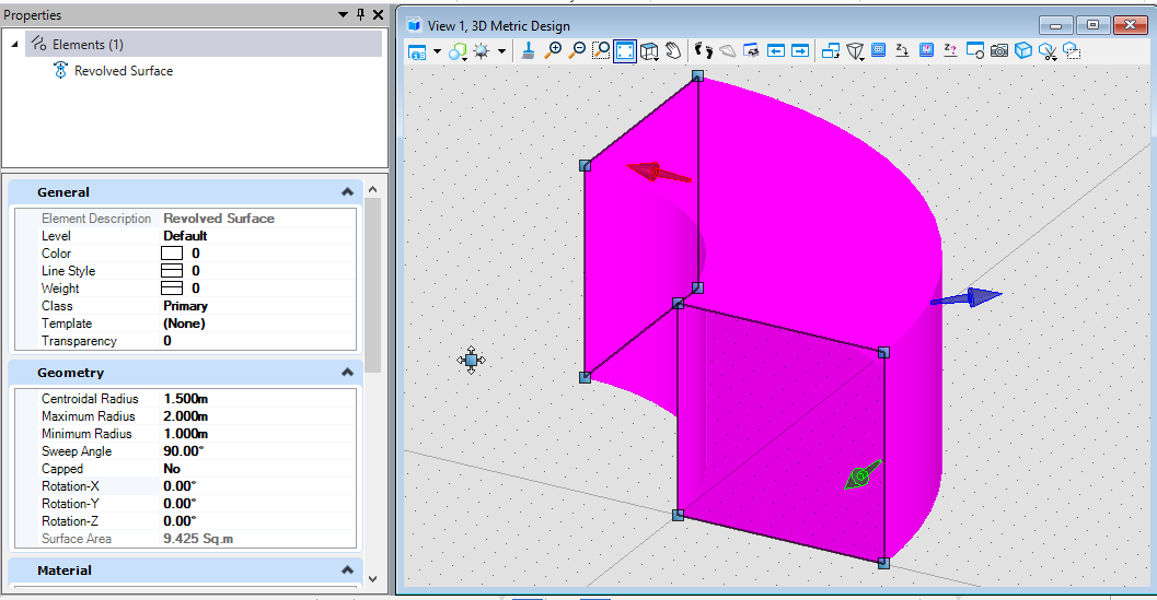
旋转面实体(SurfaceOrSolidElement)
创建旋转面实体时需要首先对旋转轮廓进行定义,然后定义旋转面实体的中心点与旋转轴,最后使用这些参数创建旋转面实体。注意:在创建旋转实体时,若preferSolid参数为真,则生成旋转体,否则生成旋转面实体。
public static void CmdCreateSurface2(string unparsed){DgnModel dgnModel = Session.Instance.GetActiveDgnModel();//获取当前的模型空间#region Create profileDPoint3d p1 = new DPoint3d(0, 0, 0);//定义形元素端点DPoint3d p2 = new DPoint3d(0, 0, 10000);DPoint3d p3 = new DPoint3d(10000, 0, 10000);DPoint3d p4 = new DPoint3d(10000, 0, 0);DPoint3d[] pos = { p1, p2, p3, p4 };//将形元素端点添加到形元素端点数组中ShapeElement shape = new ShapeElement(dgnModel, null, pos);//定义形元素#endregionDPoint3d centerPo = new DPoint3d(-10000, 0, 0);//定义旋转形元素的中心点DVector3d axis = new DVector3d(0, 0, 1);//定义旋转形元素的旋转轴SurfaceOrSolidElement surface = SurfaceOrSolidElement.CreateRevolutionElement(dgnModel, null, shape, centerPo, axis, Angle.PI.Radians / 2, false);/** 定义旋转形元素* dgnModel:定义旋转形元素的模型空间* templateElement:元素模板* profile:旋转截面* center:旋转形元素的中心点* axis:旋转轴线* sweepAngle:旋转扫掠角* preferSolid:生成旋转体还是旋转面(若为旋转体则为true)*/surface.AddToModel();//将旋转形元素写入模型}
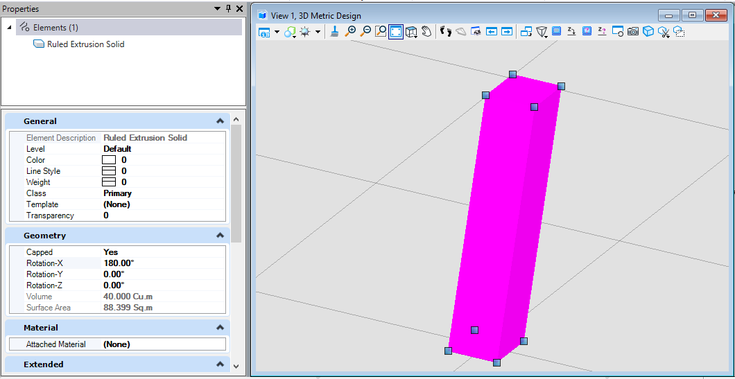
拉伸实体(SurfaceOrSolidElement)
创建拉伸实体时需要首先对拉伸轮廓进行定义,然后使用方向向量对拉伸体的拉伸方向,拉伸长度进行定义,最后使用这些定义的参数生成拉伸面。注意:在创建拉伸实体时,若preferSolid参数为真,则生成拉伸体,否则生成拉伸面实体。
public static void CmdCreateSolid1(string unparsed){DgnModel dgnModel = Session.Instance.GetActiveDgnModel();//获取当前的模型空间#region Create profileDPoint3d p1 = new DPoint3d(-10000, 10000, 0);//定义体元素端点DPoint3d p2 = new DPoint3d(10000, 10000, 0);DPoint3d p3 = new DPoint3d(10000, -10000, 0);DPoint3d p4 = new DPoint3d(-10000, -10000, 0);DPoint3d[] pos = { p1, p2, p3, p4 };//将形元素端点添加到形元素端点数组中ShapeElement shape = new ShapeElement(dgnModel, null, pos);//定义形元素#endregionDPoint3d origin = DPoint3d.Zero;//定义拉伸基点DVector3d extrudeVector = new DVector3d(10000, 10000, 100000);//定义拉伸向量SurfaceOrSolidElement solid = SurfaceOrSolidElement.CreateProjectionElement(dgnModel, null, shape, origin, extrudeVector, DTransform3d.Identity, true);/** 使用投影的方式定义拉伸体元素* dgnModel:定义拉伸体元素的模型空间* templateElement:元素模板* profile:投影轮廓面(截面)* origin:拉伸起点* extrudeVector:拉伸向量* transform:元素变换矩阵* preferSolid:生成拉伸体还是拉伸面(若为拉伸体则为true)*/solid.AddToModel();//将拉伸体写入模型}
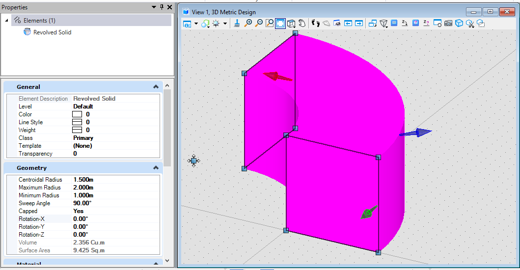
旋转实体(SurfaceOrSolidElement)
创建旋转实体时需要首先对旋转轮廓进行定义,然后定义旋转实体的中心点与旋转轴,最后使用这些参数创建旋转实体。注意:在创建旋转实体时,若preferSolid参数为真,则生成旋转体,否则生成旋转面实体。
public static void CmdCreateSolid2(string unparsed){DgnModel dgnModel = Session.Instance.GetActiveDgnModel();//获取当前的模型空间#region Create profileDPoint3d p1 = new DPoint3d(0, 0, 0);//定义形元素端点DPoint3d p2 = new DPoint3d(0, 0, 10000);DPoint3d p3 = new DPoint3d(10000, 0, 10000);DPoint3d p4 = new DPoint3d(10000, 0, 0);DPoint3d[] pos = { p1, p2, p3, p4 };//将形元素端点添加到形元素端点数组中ShapeElement shape = new ShapeElement(dgnModel, null, pos);//定义形元素#endregionDPoint3d centerPo = new DPoint3d(-10000, 0, 0);//定义旋转体元素的中心点DVector3d axis = new DVector3d(0, 0, 1);//定义旋转体元素的旋转轴SurfaceOrSolidElement solid = SurfaceOrSolidElement.CreateRevolutionElement(dgnModel, null, shape, centerPo, axis, Angle.PI.Radians / 2, true);/** 定义旋转体元素* dgnModel:定义旋转体元素的模型空间* templateElement:元素模板* profile:旋转截面* center:旋转形元素的中心点* axis:旋转轴线* sweepAngle:旋转扫掠角* preferSolid:生成旋转体还是旋转面(若为旋转体则为true)*/solid.AddToModel();//将旋转体元素写入模型}
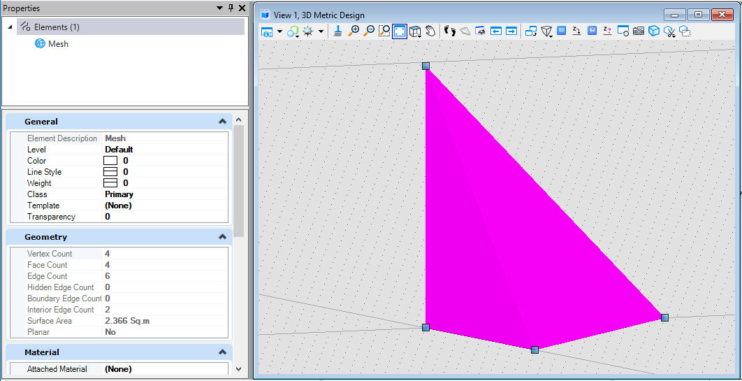
网格元素(MeshHeaderElement)
网格元素的创建方式有些复杂,首先需要创建多面体几何,若使用编程的方式创建多面体几何,需要首先确定多面体几何的端点坐标,然后根据网格的分布情况按照端点坐标的索引值连接形成局部网格并将信息添加到多面体几何中,最后使用多面体几何创建网格元素。
public static void CmdCreateMesh(string unparsed){DgnModel dgnModel = Session.Instance.GetActiveDgnModel();//获取当前的模型空间#region create polyfaceDPoint3d p1 = DPoint3d.Zero;//定义多面体端点坐标DPoint3d p2 = new DPoint3d(10000,0,0);DPoint3d p3 = new DPoint3d(0,10000,0);DPoint3d p4 = new DPoint3d(0,0,10000);IList<DPoint3d> pos = new List<DPoint3d>();//定义储存多面体坐标的列表pos.Add(p1);//将多面体端点坐标添加到列表中pos.Add(p2);pos.Add(p3);pos.Add(p4);PolyfaceHeader polyface = new PolyfaceHeader();//定义多面体几何polyface.Point= pos;//设置该多面体几何的端点集polyface.ActivateVectorsForIndexing(polyface);//激活多面体几何中的数据与索引List<int> indices = new List<int>();//定义索引列表indices.Add(1); indices.Add(2); indices.Add(3); //将索引号添加到列表中polyface.AddIndexedFacet(indices, null, null, indices);//添加索引信息到多面体几何中indices.Clear();//清空索引列表indices.Add(1); indices.Add(2); indices.Add(4);//继续将索引号添加到列表中polyface.AddIndexedFacet(indices, null, null, indices);indices.Clear();indices.Add(2); indices.Add(3); indices.Add(4);polyface.AddIndexedFacet(indices, null, null, indices);indices.Clear();indices.Add(1); indices.Add(3); indices.Add(4);polyface.AddIndexedFacet(indices, null, null, indices);#endregionMeshHeaderElement mesh = new MeshHeaderElement(dgnModel,null,polyface);//定义使用多面体几何网格元素mesh.AddToModel();//将网格元素添加到模型空间中}
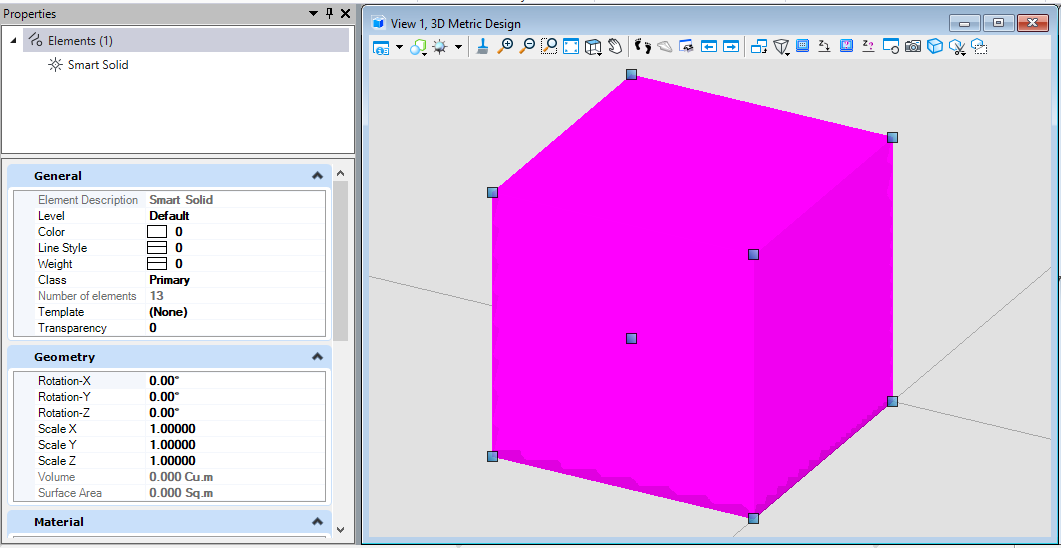
智能实体(SolidKernelEntity)-拉伸
与普通拉伸实体不同的是,智能拉伸实体是一个拉伸体到指定平面后生成的结果。首先需要创建一个拉伸体,然后再创建一个拉伸终点的平面,最后将参数输入后即生成实体拉伸到另一个平面的新实体。需要注意的是,平面必须完全将实体截断,否则无法生成最终的结果。
public static void CmdCreateSmartSolid1(string unparsed){DgnModel dgnModel = Session.Instance.GetActiveDgnModel();//获取当前的模型空间DPoint3d profilePo1 = new DPoint3d(-50000, 50000, 0);//定义拉伸体拉伸平面端点DPoint3d profilePo2 = new DPoint3d(50000, 50000, 0);DPoint3d profilePo3 = new DPoint3d(50000, -50000, 0);DPoint3d profilePo4 = new DPoint3d(-50000, -50000, 0);IList<DPoint3d> profilePos = new List<DPoint3d>() {profilePo1,profilePo2,profilePo3,profilePo4, profilePo1 };//定义拉伸体拉伸平面的端点列表CurveVector profileCurve = CurveVector.CreateLinear(profilePos,CurveVector.BoundaryType.Outer,false);//定义拉伸体拉伸平面轮廓线Create.BodyFromCurveVector(out SolidKernelEntity profileEntity,profileCurve,dgnModel);//将拉伸平面轮廓线转化为SolidKernelEntityDPoint3d extrudePo1 = new DPoint3d(-50000, 50000, -100000);//定义拉伸体截面端点DPoint3d extrudePo2 = new DPoint3d(50000, 50000, -200000);DPoint3d extrudePo3 = new DPoint3d(50000, -50000, -300000);DPoint3d extrudePo4 = new DPoint3d(-50000, -50000, -200000);IList<DPoint3d> extrudePos = new List<DPoint3d>() { extrudePo1, extrudePo2, extrudePo3, extrudePo4, extrudePo1 };//定义拉伸体截面端点列表CurveVector extrudeCurve = CurveVector.CreateLinear(extrudePos, CurveVector.BoundaryType.Outer, true);//定义拉伸体截面轮廓线Create.BodyFromCurveVector(out SolidKernelEntity extrudeEntity, extrudeCurve, dgnModel);//将截面轮廓线转化为SolidKernelEntityCreate.BodyFromExtrusionToBody(out SolidKernelEntity solid,extrudeEntity,profileEntity,false);/** 通过将平面实体拉伸到另一个平面实体来定义新实体* entityOut:新实体* extrudeToIn:修剪拉伸实体的平面实体* profileIn:要拉伸的平面实体。* reverseDirectionIn:拉伸方向是否与拉伸的平面实体法线方向相同或相反*/Convert1.BodyToElement(out Element solidElem,solid,null,dgnModel);//将实体转换为元素solidElem.AddToModel();//将元素写入模型空间}
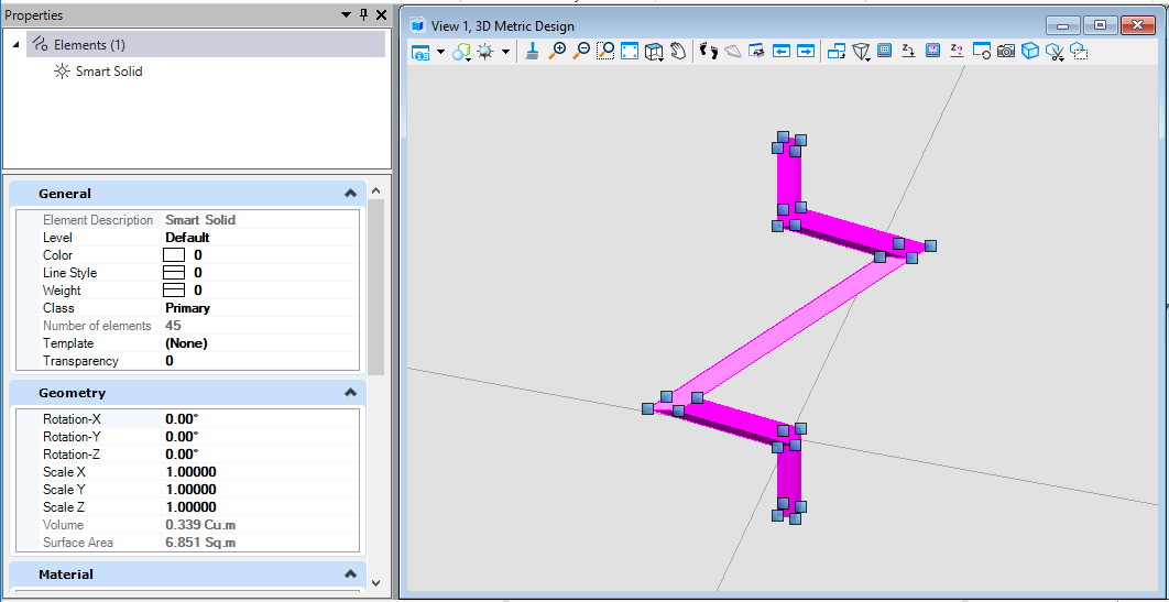
智能实体(SolidKernelEntity)-轮廓放样
轮廓放样,即我们可以通过输入拉伸体的不同轮廓进行放样融合,形成一个新的实体。在智能实体的轮廓放样中,我们需要首先定义实体的多个轮廓,他们之间会根据计算进行融合过渡,同时,也可以通过定义轮廓线的方式硬性设置轮廓的放样轨迹,最终生成实体。需要注意的是,在轮廓放样中,若不规定轮廓轨迹,依然需要在轨迹线入参中填入数据,一般可以将轮廓线列表填入,但不可不填,否则会造成程序崩溃。
public static void CmdCreateSmartSolid2(string unparsed){DgnModel dgnModel = Session.Instance.GetActiveDgnModel();//获取当前的模型空间CurveVector[] profilesIn = new CurveVector[3];//定义截面曲线数组DPoint3d[] ptArr_Section0 = new DPoint3d[4];//定义截面端点数组ptArr_Section0[0] = new DPoint3d(-500, 500, 0);//定义截面端点ptArr_Section0[1] = new DPoint3d(500, 500, 0);ptArr_Section0[2] = new DPoint3d(500, -500, 0);ptArr_Section0[3] = new DPoint3d(-500, -500, 0);ShapeElement shp0 = new ShapeElement(dgnModel, null, ptArr_Section0);//定义形元素profilesIn[0] = CurvePathQuery.ElementToCurveVector(shp0);//将面转换为曲线DPoint3d[] ptArr_Section1 = new DPoint3d[4];ptArr_Section1[0] = new DPoint3d(0, 1000, 5000);ptArr_Section1[1] = new DPoint3d(1000, 0, 5000);ptArr_Section1[2] = new DPoint3d(0, -1000, 5000);ptArr_Section1[3] = new DPoint3d(-1000, 0, 5000);ShapeElement shp1 = new ShapeElement(dgnModel, null, ptArr_Section1);profilesIn[1] = CurvePathQuery.ElementToCurveVector(shp1);DPoint3d[] ptArr_Section2 = new DPoint3d[4];ptArr_Section2[0] = new DPoint3d(-500, 500, 10000);ptArr_Section2[1] = new DPoint3d(500, 500, 10000);ptArr_Section2[2] = new DPoint3d(500, -500, 10000);ptArr_Section2[3] = new DPoint3d(-500, -500, 10000);ShapeElement shp2 = new ShapeElement(dgnModel, null, ptArr_Section2);profilesIn[2] = CurvePathQuery.ElementToCurveVector(shp2);BentleyStatus result = Create.BodyFromLoft(out SolidKernelEntity entityOut, profilesIn, 3, profilesIn, 0, dgnModel, false, false);/** 定义一组轮廓线放样定义实体* entityOut:定义的放样实体* profilesIn:横截面轮廓集* nProfilesIn:横截面数量* guidesIn:(可选)用于控制放样曲线轨迹的曲线集 注意:若不使用控制曲线,该位置可将横截面轮廓集填到此处,不可为空,否则会报错* nGuidesIn:控制放样曲线轨迹的曲线数量* modelRefIn:获取当前模型的比例单位* periodicIn:若为真,则会构造一个闭合曲面,其中第一条截面将作为最后一条截面* segmentIn:若为真,每个截面间将定义线性曲线而不做平滑*/result = Convert1.BodyToElement(out Element eeh, entityOut, null, dgnModel);//将SolidKernelEntity转换为元素eeh.AddToModel();//将元素写入模型}
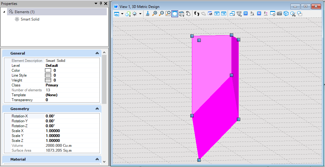
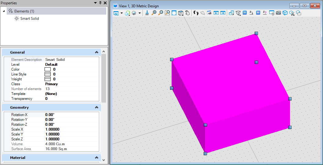
智能实体(SolidKernelEntity)-拉伸
智能拉伸实体的创建方法与普通拉伸实体的创建方式类似。首先创建一个智能拉伸实体的外轮廓线和拉伸向量,记录拉伸长度及拉伸方向,然后使用该模型创建普通实体,最后将普通实体转化为智能实体。
public static void CmdCreateSmartSolid3(string unparsed){DgnModel dgnModel = Session.Instance.GetActiveDgnModel();//获取当前的模型空间DPoint3d p1 = new DPoint3d(10000,10000);//定义截面轮廓线端点DPoint3d p2 = new DPoint3d(10000,-10000);DPoint3d p3 = new DPoint3d(-10000,-10000);DPoint3d p4 = new DPoint3d(-10000,10000);IList<DPoint3d> pos = new List<DPoint3d>() { p1,p2,p3,p4};//定义轮廓线端点数组CurveVector curve = CurveVector.CreateLinear(pos,CurveVector.BoundaryType.Outer,true);//定义轮廓线DVector3d vector = new DVector3d(0,0,10000);//定义拉伸向量(包含拉伸长度及方向信息)DgnExtrusionDetail detail = new DgnExtrusionDetail(curve, vector,true);/** 定义拉伸信息* baseCurve:截面轮廓曲线* extrusionVector:拉伸信息* capped:若启用端盖则为真*/SolidPrimitive solid = SolidPrimitive.CreateDgnExtrusion(detail);//使用拉伸信息定义实体BentleyStatus result = Create.BodyFromSolidPrimitive(out SolidKernelEntity entityOut, solid,dgnModel);//使用拉伸实体定义SolidKernelEntityresult = Convert1.BodyToElement(out Element eeh, entityOut, null, dgnModel);//将SolidKernelEntity转换为元素eeh.AddToModel();//将元素写入模型}
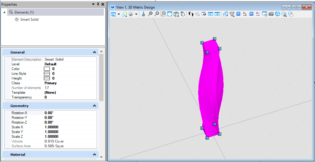
智能实体(SolidKernelEntity)-扫掠
创建智能扫掠实体时需要首先使用曲线定义扫掠的轮廓线,然后定义扫掠的轨迹线,最后使用轮廓线及轨迹线,结合扫掠属性,比如说是否修复扫掠自交,是否在扫掠过程中旋转轮廓截面,沿路径扫掠截面是否需要变化等属性生成最终的智能扫掠实体。
public static void CmdCreateSmartSolid4(string unparsed){DgnModel dgnModel = Session.Instance.GetActiveDgnModel();//获取当前的模型空间DPoint3d profilePo1 = new DPoint3d(1000, 1000,-10000);//定义截面轮廓线端点DPoint3d profilePo2 = new DPoint3d(1000, -1000, -10000);DPoint3d profilePo3 = new DPoint3d(-1000, -1000, -10000);DPoint3d profilePo4 = new DPoint3d(-1000, 1000, -10000);DPoint3d[] profilePos = { profilePo1 , profilePo2, profilePo3, profilePo4};//定义截面轮廓线端点集ShapeElement shape = new ShapeElement(dgnModel,null, profilePos);//定义形元素CurveVector curve= CurvePathQuery.ElementToCurveVector(shape);//使用图形元素获得轮廓线DPoint3d pathPo1 = new DPoint3d(0, 0, -10000);//定义扫掠轨迹线端点DPoint3d pathPo2 =new DPoint3d(0, 0,0);DPoint3d pathPo3 = new DPoint3d(10000,10000,10000);DPoint3d pathPo4 = new DPoint3d(-10000, -10000, 20000);DPoint3d pathPo5 = new DPoint3d(0, 0, 30000);DPoint3d pathPo6 = new DPoint3d(0, 0, 40000);DPoint3d[] pathPos = { pathPo1, pathPo2, pathPo3, pathPo4 , pathPo5, pathPo6};//定义扫掠轨迹端点集LineStringElement lineString = new LineStringElement(dgnModel,null, pathPos);//定义线串元素CurveVector pathCurve = lineString.GetCurveVector();//使用线串元素获得扫掠轨迹点Create.BodyFromSweep(out SolidKernelEntity entityOut, curve, pathCurve, dgnModel, false, true, false,null, null,null , null);/** 使用横截面扫掠路径定义实体* entityOut:生成的新实体* profileIn:横断面轮廓(开放,闭合或带孔区域)* pathIn:扫掠轨迹线* modelRefIn:获取当前模型的比例单位* alignParallelIn:若为真,则轮廓与全局轴线保持固定角度,而不是与路径相切并锁定方向* selfRepairIn:若为真,则会尝试修复扫掠自交* createSheetIn:若为真,则会强制生成闭合的扫掠实体* lockDirectionIn:(可选)使截面轮廓与垂直于方向向量同时切线保持固定角度,仅当alignParallelIn为真时有效* twistAngleIn:(可选)在轮廓沿路径移动时旋转轮廓角度* scaleIn:(可选)在轮廓沿路径扫掠时缩放比例* scalePointIn:应用缩放需要缩放的轮廓端点*/BentleyStatus result = Convert1.BodyToElement(out Element eeh, entityOut, null, dgnModel);//将SolidKernelEntity转换为元素eeh.AddToModel();//将元素写入模型}
智能实体(SolidKernelEntity)-缝合
该方法的思路与创建网格元素有些类似,简单来说就是首先创建构成智能实体的子实体,然后将这些子实体缝合为一个整体的智能实体。首先创建组成智能实体的形元素,然后将形元素转换为实核实体,最后使用实核实体缝合成为智能实体。
public static void CmdCreateSmartSolid5(string unparsed){List<DPoint3d> points = new List<DPoint3d>();//定义坐标列表points.Add(new DPoint3d(0, 0, 0));//给列表添加坐标points.Add(new DPoint3d(10, 0, 0));points.Add(new DPoint3d(10, 10, 0));points.Add(new DPoint3d(0, 10, 0));ShapeElement shape1 = new ShapeElement(Session.Instance.GetActiveDgnModel(), null, points.ToArray());//定义形元素points.Clear();//清空列表元素points.Add(new DPoint3d(0, 0, 0));points.Add(new DPoint3d(10, 0, 0));points.Add(new DPoint3d(10, 0, 10));points.Add(new DPoint3d(0, 0, 10));ShapeElement shape2 = new ShapeElement(Session.Instance.GetActiveDgnModel(), null, points.ToArray());points.Clear();points.Add(new DPoint3d(0, 10, 0));points.Add(new DPoint3d(10, 10, 0));points.Add(new DPoint3d(10, 10, 10));points.Add(new DPoint3d(0, 10, 10));ShapeElement shape3 = new ShapeElement(Session.Instance.GetActiveDgnModel(), null, points.ToArray());points.Clear();points.Add(new DPoint3d(10, 0, 0));points.Add(new DPoint3d(10, 10, 0));points.Add(new DPoint3d(10, 10, 10));points.Add(new DPoint3d(10, 0, 10));ShapeElement shape4 = new ShapeElement(Session.Instance.GetActiveDgnModel(), null, points.ToArray());points.Clear();points.Add(new DPoint3d(0, 0, 0));points.Add(new DPoint3d(0, 10, 0));points.Add(new DPoint3d(0, 10, 10));points.Add(new DPoint3d(0, 0, 10));ShapeElement shape5 = new ShapeElement(Session.Instance.GetActiveDgnModel(), null, points.ToArray());points.Clear();points.Add(new DPoint3d(0, 0, 10));points.Add(new DPoint3d(0, 10, 10));points.Add(new DPoint3d(10, 10, 10));points.Add(new DPoint3d(10, 0, 10));ShapeElement shape6 = new ShapeElement(Session.Instance.GetActiveDgnModel(), null, points.ToArray());SolidKernelEntity[] tools1 = new SolidKernelEntity[6];//定义实核实体列表Convert1.ElementToBody(out tools1[0], shape1, false, true, false);//将Shape元素转换为实核实体Convert1.ElementToBody(out tools1[1], shape2, false, true, false);Convert1.ElementToBody(out tools1[2], shape3, false, true, false);Convert1.ElementToBody(out tools1[3], shape4, false, true, false);Convert1.ElementToBody(out tools1[4], shape5, false, true, false);Convert1.ElementToBody(out tools1[5], shape6, false, true, false);BrepCellHeaderElement brepCellHeader = null;//初始化智能实体if (BentleyStatus.Success == Modify.SewBodies(out SolidKernelEntity[] sewn1, out SolidKernelEntity[] unsewn1, ref tools1, 6, 0, 1))//缝合实核实体{for (int i = 0; i < sewn1.Length; i++)//遍历缝合结果{brepCellHeader = new BrepCellHeaderElement(Session.Instance.GetActiveDgnModel(), null, sewn1[i]);//定义智能实体brepCellHeader.AddToModel();//将智能实体写入模型}}}
其他
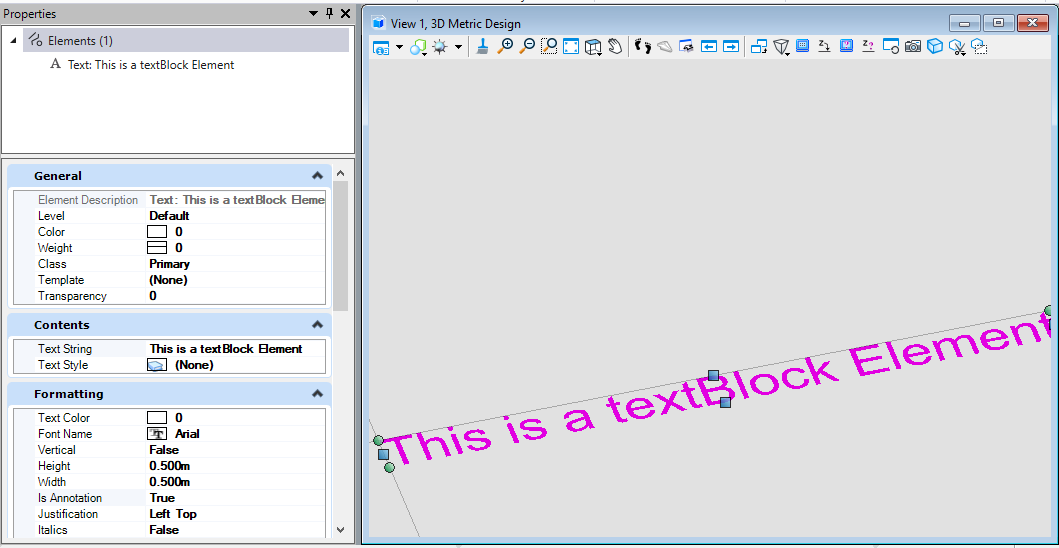
文字元素(TextElement)
在创建文字元素时,我们需要首先定义文本块的属性,其中包括文字样式,文字段落属性等,定义后再对文本块中输出的内容进行输入,最后生成文本元素。
public static void CmdCreateText(string unparsed){DgnFile dgnFile = Session.Instance.GetActiveDgnFile();//获得定义文本元素的文件DgnModel dgnModel = Session.Instance.GetActiveDgnModel();//获得定义文本元素的模型空间TextBlockProperties txtBlockProp = new TextBlockProperties(dgnModel);//定义文本属性txtBlockProp.IsViewIndependent = false;//设置文本非独立于视图ParagraphProperties paraProp = new ParagraphProperties(dgnModel);//定义段落属性DgnTextStyle txtStyle = DgnTextStyle.GetSettings(dgnFile);//从激活的文件中获得文字样式RunProperties runProp = new RunProperties(txtStyle, dgnModel);//定义运行属性TextBlock txtBlock = new TextBlock(txtBlockProp, paraProp, runProp, dgnModel);//定义文本块txtBlock.AppendText("This is a textBlock Element");//设置文本块文字内容TextElement text = (TextElement) TextElement.CreateElement(null, txtBlock);//定义文本元素text.AddToModel();//将生成的文本元素写入模型}
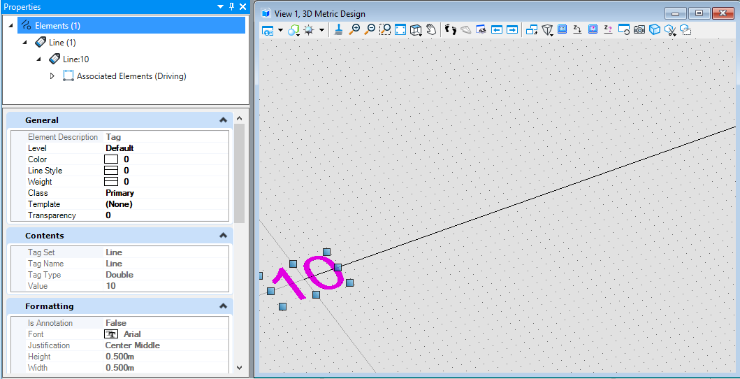
标签元素(TagElement)
创建标签元素需要首先确定标签依附的对象,在本案例中我们首先创建了一个用于依附的线元素,然后创建标签的属性定义,其中包含标签名称,标签值等,然后将标签集写入模型。最后在创建标签元素时将用于依附的线元素,标签定义输入生成结果。
public static void CmdCreateTag(string unparsed){DgnFile dgnFile = Session.Instance.GetActiveDgnFile();//获得定义文本元素的文件DgnModel dgnModel = Session.Instance.GetActiveDgnModel();//获得定义文本元素的模型空间LineElement line = new LineElement(dgnModel, null, new DSegment3d(0, 0, 0, 50000, 0, 0));//定义需要标注的直线line.AddToModel();//将直线写入模型DgnTagDefinition[] tagDefs = new DgnTagDefinition[1];//定义标签定义数组tagDefs[0] = new DgnTagDefinition();//定义标签定义tagDefs[0].Name = "Line";//设置标签名称tagDefs[0].TagDataType = TagType.Double;//设置标签类型tagDefs[0].Value = 10.0;//设置标签值TagSetElement tagSet = new TagSetElement(dgnModel, tagDefs, tagDefs[0].Name, "", true, dgnFile, 0);//定义标签集元素tagSet.AddToModel();//将标签集元素写入模型DPoint3d origin = DPoint3d.FromXYZ(0, 0, 0);//设置标签元素插入点DMatrix3d orientation = DMatrix3d.Identity;//设置标签变换矩阵DgnTextStyle style = DgnTextStyle.GetSettings(dgnFile);//从当前激活的文件中获得文字样式TagElement tag = new TagElement(dgnModel, null, tagSet.SetName, tagSet.SetName, null, style, false, origin, orientation, line);//定义标注元素tag.AddToModel();//将标注元素写入模型}
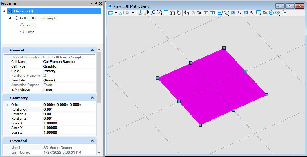
普通单元(CellHeaderElement)
在创建普通单元时我们需要将构成该单元的所有子元素添加到元素集中,然后使用元素集中的元素,指定创建普通单元的模型空间,名称,坐标,旋转矩阵等信息后生成结果。
public static void CmdCreateCell(string unparsed){DgnModel dgnModel = Session.Instance.GetActiveDgnModel();//获得定义文本元素的模型空间DPoint3d[] ptArr = new DPoint3d[5];//定义形元素端点集ptArr[0] = new DPoint3d(-15 * 10000, -5 * 10000, 0 * 10000);//定义端点坐标ptArr[1] = new DPoint3d(-15 * 10000, 5 * 10000, 0 * 10000);ptArr[2] = new DPoint3d(-5 * 10000, 5 * 10000, 0 * 10000);ptArr[3] = new DPoint3d(-5 * 10000, -5 * 10000, 0 * 10000);ptArr[4] = new DPoint3d(-15 * 10000, -5 * 10000, 0 * 10000);ShapeElement shapeEle = new ShapeElement(dgnModel, null, ptArr);//定义形元素DPlacementZX dPlaceZX = DPlacementZX.Identity;//定义椭圆放置平面dPlaceZX.Origin = new DPoint3d(-10 * 10000, 0, 0);//设置平面原点DEllipse3d ellipse = new DEllipse3d(dPlaceZX, 5 * 10000, 5 * 10000, Angle.Zero, Angle.TWOPI);//定义几何椭圆EllipseElement elliElem = new EllipseElement(dgnModel, null, ellipse);//定义椭圆元素List<Element> listElems = new List<Element>();//定义单元组成元素集listElems.Add(shapeEle);//将构成元素添加到元素集中listElems.Add(elliElem);DPoint3d ptOri = new DPoint3d();//设置单元放置位置DMatrix3d rMatrix = DMatrix3d.Identity;//设置变换矩阵DPoint3d ptScale = new DPoint3d(1, 1, 1);//设置缩放比例CellHeaderElement cellHeaderEle = new CellHeaderElement(dgnModel, "CellElementSample", ptOri, rMatrix, listElems);//定义单元cellHeaderEle.AddToModel();//将单元写入模型空间}
共享单元(SharedCellElement)
在创建共享单元前需要首先在模型中定义共享单元定义。在创建共享单元定义时需要将构成共享单元定义的子元素添加到定义元素中,而后写入模型。然后在创建共享单元时设置其共享单元定义,最后将定义的共享单元写入模型。
public static void CmdCreateSharedCell(string unparsed){DgnModel dgnModel = Session.Instance.GetActiveDgnModel();//获得定义文本元素的模型空间DPoint3d[] ptArr = new DPoint3d[5];//定义形元素端点集ptArr[0] = new DPoint3d(-15 * 10000, -5 * 10000, 0 * 10000);//定义端点坐标ptArr[1] = new DPoint3d(-15 * 10000, 5 * 10000, 0 * 10000);ptArr[2] = new DPoint3d(-5 * 10000, 5 * 10000, 0 * 10000);ptArr[3] = new DPoint3d(-5 * 10000, -5 * 10000, 0 * 10000);ptArr[4] = new DPoint3d(-15 * 10000, -5 * 10000, 0 * 10000);ShapeElement shapeEle = new ShapeElement(dgnModel, null, ptArr);//定义形元素DPlacementZX dPlaceZX = DPlacementZX.Identity;//定义椭圆放置平面dPlaceZX.Origin = new DPoint3d(-10 * 10000, 0, 0);//设置平面原点DEllipse3d ellipse = new DEllipse3d(dPlaceZX, 5 * 10000, 5 * 10000, Angle.Zero, Angle.TWOPI);//定义几何椭圆EllipseElement elliElem = new EllipseElement(dgnModel, null, ellipse);//定义椭圆元素SharedCellDefinitionElement sharedCellDefinition = new SharedCellDefinitionElement(dgnModel,"test");//定义共享单元定义元素sharedCellDefinition.AddChildElement(shapeEle);//将构成元素添加到共享单元定义元素中sharedCellDefinition.AddChildElement(elliElem);sharedCellDefinition.AddChildComplete();//添加构件完成sharedCellDefinition.AddToModel();//将共享单元定义元素写入模型DPoint3d origin = DPoint3d.Zero;//设置插入点坐标DPoint3d scale = new DPoint3d(1,1,1);//设置缩放比例SharedCellElement sharedCell = new SharedCellElement(dgnModel,null,"testCell", origin,DMatrix3d.Identity, scale);//定义共享单元元素sharedCell.SetDefinitionId(sharedCellDefinition.ElementId);//指定该共享单元的定义元素TransformInfo transInfo = new TransformInfo(DTransform3d.Identity);//定义变换信息sharedCell.ApplyTransform(transInfo);//对共享单元元素应用变换信息sharedCell.AddToModel();//将共享单元添加到模型中}

标注元素(DimensionElement)
创建标注元素时需要首先设定标注样式,然后创建一个抽象类DimensionCreateData的具体实现应用设置的标注样式,最后在设置标注的起点及终点及标注线高度等属性后生成结果。
public static void CmdCreateDimension(string unparsed){DgnFile dgnFile = Session.Instance.GetActiveDgnFile();//获得当前激活的文件DgnModel dgnModel = Session.Instance.GetActiveDgnModel();//获得当前激活的模型空间//获取当前dgn文件中名字为"DimStyle"的标注样式,尺寸标注元素的外貌由上百个属性控制,而标注样式是一组预先设置好的属性//获取了预先订制好的标注样式之后,还可以调用DimensionStyle下的各种SetXXX成员函数修改设置的属性DimensionStyle dimStyle = new DimensionStyle("DimStyle", dgnFile);//定义标注样式dimStyle.SetBooleanProp(true, DimStyleProp.Placement_UseStyleAnnotationScale_BOOLINT);//设置标注样式dimStyle.SetDoubleProp(1, DimStyleProp.Placement_AnnotationScale_DOUBLE);dimStyle.SetBooleanProp(true, DimStyleProp.Text_OverrideHeight_BOOLINT);dimStyle.SetDistanceProp(0.5 * 10000, DimStyleProp.Text_Height_DISTANCE, dgnModel);dimStyle.SetBooleanProp(true, DimStyleProp.Text_OverrideWidth_BOOLINT);dimStyle.SetDistanceProp(0.4 * 10000, DimStyleProp.Text_Width_DISTANCE, dgnModel);dimStyle.SetBooleanProp(true, DimStyleProp.General_UseMinLeader_BOOLINT);dimStyle.SetDoubleProp(0.01, DimStyleProp.Terminator_MinLeader_DOUBLE);dimStyle.SetBooleanProp(true, DimStyleProp.Value_AngleMeasure_BOOLINT);dimStyle.SetAccuracyProp((byte)AnglePrecision.Use1Place, DimStyleProp.Value_AnglePrecision_INTEGER);int alignInt = (int)DimStyleProp_General_Alignment.True;StatusInt status = dimStyle.SetIntegerProp(alignInt, DimStyleProp.General_Alignment_INTEGER);dimStyle.GetIntegerProp(out int valueOut, DimStyleProp.General_Alignment_INTEGER);DgnTextStyle textStyle = new DgnTextStyle("TestStyle", dgnFile);//设置文字样式LevelId lvlId = Settings.GetLevelIdFromName("Default");//设置图层CreateDimensionCallbacks callbacks = new CreateDimensionCallbacks(dimStyle, textStyle, new Symbology(), lvlId, null);//尺寸标注元素的构造函数会调用DimensionCreateData的各个成员函数去获取定义尺寸标注元素需要的各种参数DimensionElement dimEle = new DimensionElement(dgnModel, callbacks, DimensionType.SizeArrow);//定义标注元素if (dimEle.IsValid)//判断标注元素是否有效{DPoint3d pt1 = DPoint3d.Zero, pt2 = DPoint3d.FromXY(10000 * 10, 10000 * 0);//设置插入点坐标dimEle.InsertPoint(pt1, null, dimStyle, -1);//对标注元素设置插入点dimEle.InsertPoint(pt2, null, dimStyle, -1);dimEle.SetHeight(10000);//设置尺寸标注元素的高度dimEle.SetRotationMatrix(DMatrix3d.Identity);//设置变换信息dimEle.AddToModel();//将标注元素写入模型}}class CreateDimensionCallbacks : DimensionCreateData{private DimensionStyle m_dimStyle;private DgnTextStyle m_textStyle;private Symbology m_symbology;private LevelId m_levelId;private DirectionFormatter m_directionFormatter;public CreateDimensionCallbacks(DimensionStyle dimStyle, DgnTextStyle textStyle, Symbology symb, LevelId levelId, DirectionFormatter formatter){m_dimStyle = dimStyle;m_textStyle = textStyle;m_symbology = symb;m_levelId = levelId;m_directionFormatter = formatter;}public override DimensionStyle GetDimensionStyle(){return m_dimStyle;}public override DgnTextStyle GetTextStyle(){return m_textStyle;}public override Symbology GetSymbology(){return m_symbology;}public override LevelId GetLevelId(){return m_levelId;}public override int GetViewNumber(){return 0;}//此函数返回的旋转矩阵与GetViewRotation返回的旋转矩阵共同定义了尺寸标注元素的方向public override DMatrix3d GetDimensionRotation(){return DMatrix3d.Identity;}public override DMatrix3d GetViewRotation(){return DMatrix3d.Identity;}//用于从数字方向值构造字符串。public override DirectionFormatter GetDirectionFormatter(){return m_directionFormatter;}}
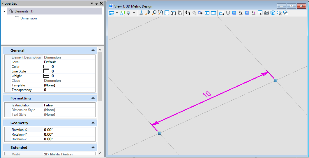
图36 绘制结果

若有收获,就点个赞吧
0 人点赞
