第四期视频回放
第四期代码及课件下载地址
第四期直播内容文字版
遍历方法介绍
引言
我们进行元素类型筛选时,一般来说需要使用Element的MSElementType属性对元素加以区别,其中对MicroStation软件中所有的元素均进行定义。
public enum MSElementType{None = 0,CellHeader = 2,Line = 3,LineString = 4,GroupData = 5,Shape = 6,TextNode = 7,DigSetData = 8,DgnFileHeader = 9,LevSym = 10,Curve = 11,ComplexString = 12,ComplexShape = 14,Ellipse = 15,Arc = 16,Text = 17,Surfce = 18,Solid = 19,BsplinePole = 21,PointString = 22,Cone = 23,BsplineSurface = 24,BsurfBoundary = 25,BsplineKnot = 26,BsplineCurve = 27,BsplineWeight = 28,Dimension = 33,SharedCellDefinition = 34,SharedCellInstance = 35,Multiline = 36,Tag = 37,DgnStoreComponent = 38,DgnStoreHeader = 39,Type44 = 44,MicroStation = 66,RasterHeader = 87,RasterComponent = 88,RasterReference = 90,RasterReferenceComponent = 91,RasterHierarchy = 92,RasterHierarchyComponent = 93,RasterFrame = 94,TableEntry = 95,Table = 96,ViewGroup = 97,View = 98,LevelMask = 99,ReferenceAttachment = 100,MeshHeader = 105,MaxElements = 113}
对于MicroStation中的大多数元素,比如说普通实体,线元素,标签元素,弧元素等均可以被成功识别,但是对于某些元素,仅凭MSElementType属性无法对元素类型进行区分。在文件名为ElementType的案例中,模型中建立了较为常用的元素,我们首先获取模型中的元素并对元素进行遍历,通过输出结果我们可以发现,采用GetGraphicElements( )方法遍历时暴露出以下三个问题:
- 无法区分普通单元与智能实体——因为他们的元素类型均为CellHeader
- 无法区分参数化实体与参数化单元——因为他们的元素类型均为106
无法区分独立元素与内嵌于参数化实体中的元素
public static void DistinguishElementType(string unparsed)//Case:ElementType{DgnModel dgnModel = Session.Instance.GetActiveDgnModel();//获得当前激活的模型ModelElementsCollection elems = dgnModel.GetGraphicElements();//获得当前模型中的所有图形元素string elemTypes = null;//声明字符串foreach (Element elem in elems)//遍历模型中的所有图形元素{elemTypes = elemTypes + "ElementId = " + elem.ElementId + " Element type = " + elem.ElementType + '\n';//输出图形元素的元素ID和元素类型}MessageBox.Show(elemTypes);//输出字符串结果}

图2 模型元素一览

图3 遍历元素与模型中元素结果对比
遍历区分智能实体与普通单元
若需要获得智能实体,那么仅凭MSElementType就只能获取到智能实体与普通单元的集合,在此基础上,我们可以使用元素的TypeName作进一步的区分,保证获得到的是智能实体。
public static void DistinguishTypeofCellHeader(string unparsed)//Case:DistinguishCellHeader{DgnModel dgnModel = Session.Instance.GetActiveDgnModel();//获得当前激活的模型ModelElementsCollection elems = dgnModel.GetGraphicElements();//获得当前模型中的所有图形元素string elemTypes = "Smart Solid:\n";//声明字符串foreach (Element elem in elems)//遍历模型中的所有图形元素{if (elem.ElementType == MSElementType.CellHeader &&elem.TypeName.Contains("Smart Solid"))//根据元素类型为CellHeader和元素类型名称判断是否为智能实体{elemTypes = elemTypes + "ElementId = " + elem.ElementId + " Element type = " + elem.ElementType + '\n';//输出图形元素的元素ID和元素类型}}MessageBox.Show(elemTypes);//输出字符串结果}
在文件名为DistinguishCellHeader的案例中,模型内创建了两个智能实体与五个普通单元,采用元素中ElementType和TypeName两个属性便可成功识别出智能实体。<br />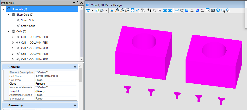<br />**图4 模型元素一览**<br />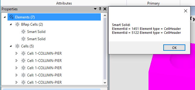<br />**图5 筛选结果**
遍历区分参数化实体与参数化单元
若需要获得参数化实体,那么仅凭MSElementType就只能获取到参数化实体与参数化单元的集合,在此基础上,我们可以使用元素的TypeName作进一步的区分,保证获得到的是参数化实体。
public static void DistinguishTypeofExtendedHeader(string unparsed)//Case:DistinguishExtendedHeader{DgnModel dgnModel = Session.Instance.GetActiveDgnModel();//获得当前激活的模型ModelElementsCollection elems = dgnModel.GetGraphicElements();//获得当前模型中的所有图形元素string elemTypes = "Parametric Solid/Surface:\n";//声明字符串foreach (Element elem in elems)//遍历模型中的所有图形元素{if ((int)elem.ElementType == 106 &&elem.TypeName == "Parametric Solid/Surface")//根据元素类型为106和元素类型名称判断是否为参数化实体/面{elemTypes = elemTypes + "ElementId = " + elem.ElementId + " Element type = " + elem.ElementType + '\n';//输出图形元素的元素ID和元素类型}}MessageBox.Show(elemTypes);//输出字符串结果}
在文件名为DistinguishExtendedHeader的案例中建立了4个参数化单元与3个参数化实体,在这里便可以使用TypeName进行区分,获取参数化实体。<br />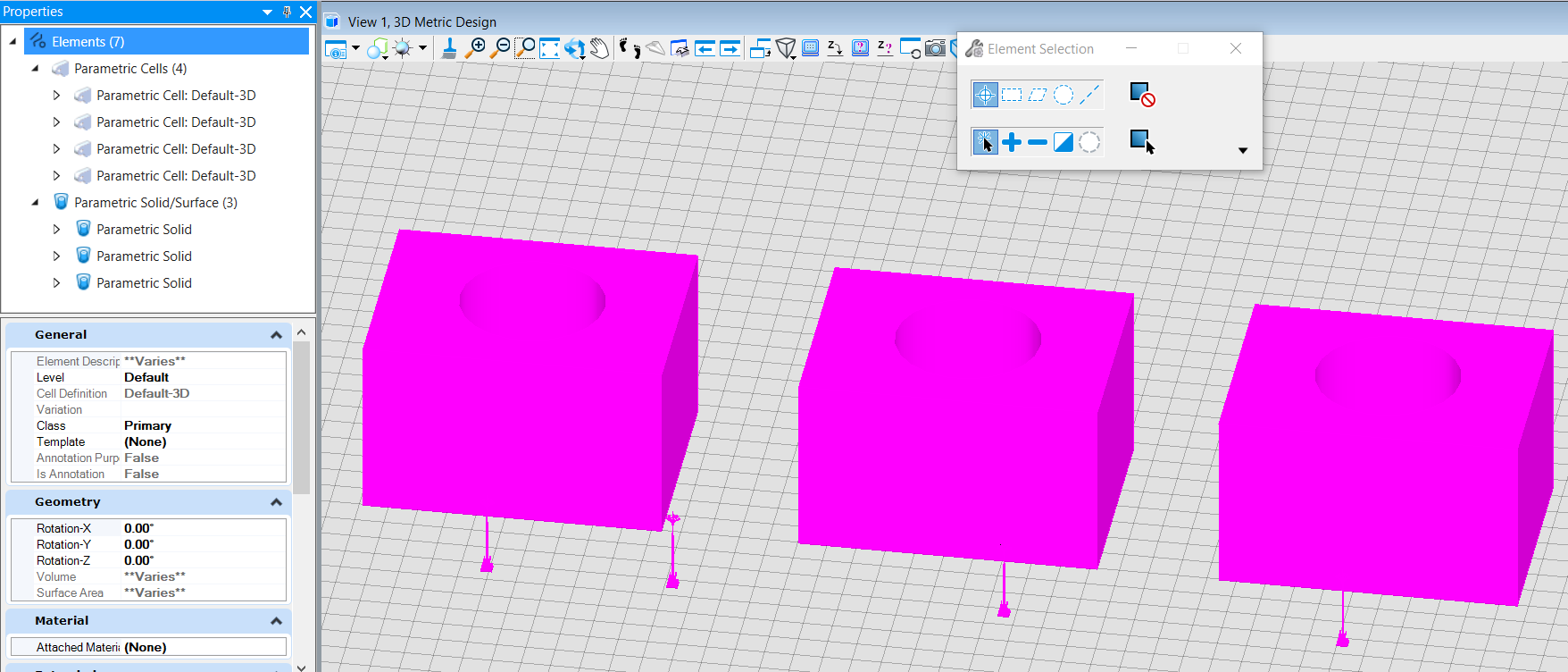<br />**图6 模型元素一览**<br /> 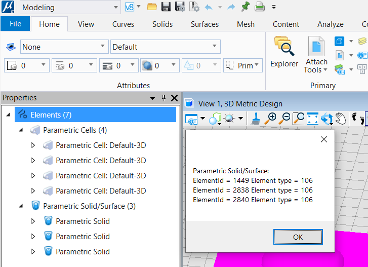<br />**图7 筛选结果**
遍历区分独立实体与内嵌实体
在进行元素筛选遍历时,若参数化实体中使用普通实体进行切割,那么在元素集中,会将二者同时识别为实体,但是内嵌于参数化实体中的实体往往并不是我们所需要获得的,同时,内嵌实体的获得还会大大影响元素筛选的准确性。因此,如何区分独立实体与内嵌实体便显得十分重要。在这里,我们使用元素中的IsInvisible属性判断元素是否为内嵌元素。当前,我们可以看到IsInvisible是可读可写的,因此采用这种方法并不是十分严谨,后续我们还会介绍其他方法来如何更加有效的区分两者,这种方法对于一般情况下是适用的。
public static void DistinguishNestingElements(string unparsed)//Case:ElementType{DgnModel dgnModel = Session.Instance.GetActiveDgnModel();//获得当前激活的模型ModelElementsCollection elems = dgnModel.GetGraphicElements();//获得当前模型中的所有图形元素string elemTypes = "Solid:\n";//声明字符串foreach (Element elem in elems)//遍历模型中的所有图形元素{if (elem.ElementType == MSElementType.Solid &&elem.IsInvisible == false)//根据元素类型为Solid和元素是否可见判断(注:该筛选方案不严谨,因有方法可修改元素是否可见){elemTypes = elemTypes + "ElementId = " + elem.ElementId + " Element type = " + elem.ElementType + '\n';//输出图形元素的元素ID和元素类型}}MessageBox.Show(elemTypes);//输出字符串结果}
在文件名为ElementType的案例中我们使用以上方法,可以过滤掉参数化实体中内嵌的实体元素,获得独立的实体元素集。<br />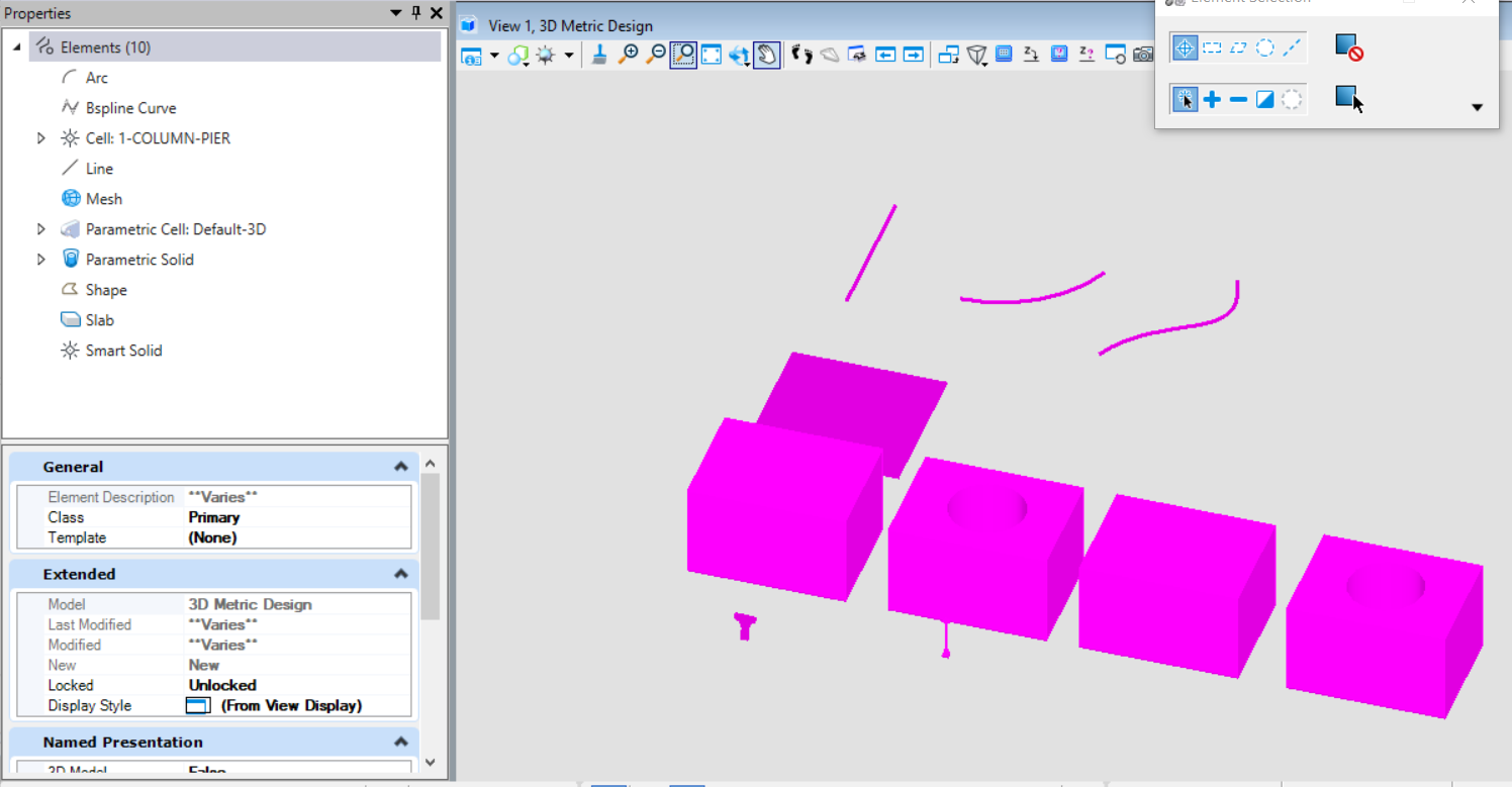<br />**图8 模型元素一览**<br />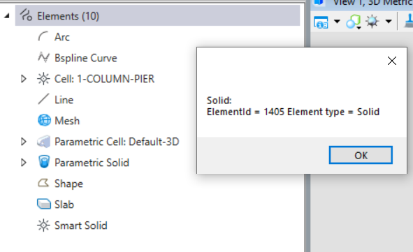<br />**图9 筛选结果**
选择集使用方法介绍
获得选择集中的元素
基于MicroStation中强大的选择集功能,可以直接使用选择集中图层,颜色,线形,元素类型,元素模板等对元素进行过滤,该方法介绍了如何读取到选择集中的元素。通过对于在选择集中获取到元素我们还可以根据业务的实际需求进一步的筛选元素,以达到获取目标元素集的最终目的。
public static void QueryElemsInSelection(string unparsed)//Case:DistinguishNestingElement{ElementAgenda agenda = new ElementAgenda();//声明元素容器SelectionSetManager.BuildAgenda(ref agenda);//从当前选择集中获得元素string result = "The selected elements:\n";//声明字符串for (uint i = 0; i < agenda.GetCount(); i++)//遍历选择集中的所有元素{result = result + i + 1 + ": ElementId = " + agenda.GetEntry(i).ElementId + ", Element type = " + agenda.GetEntry(i).ElementType + "\n";//将元素ID与元素类型信息写入字符串中}MessageBox.Show(result);//输出字符串结果}
在文件名为DistinguishNestingElement的案例中,我首先使用选择集框选出我需要操作的元素,如下图所示,完成后执行上方代码,最终获得选择集中的元素。<br />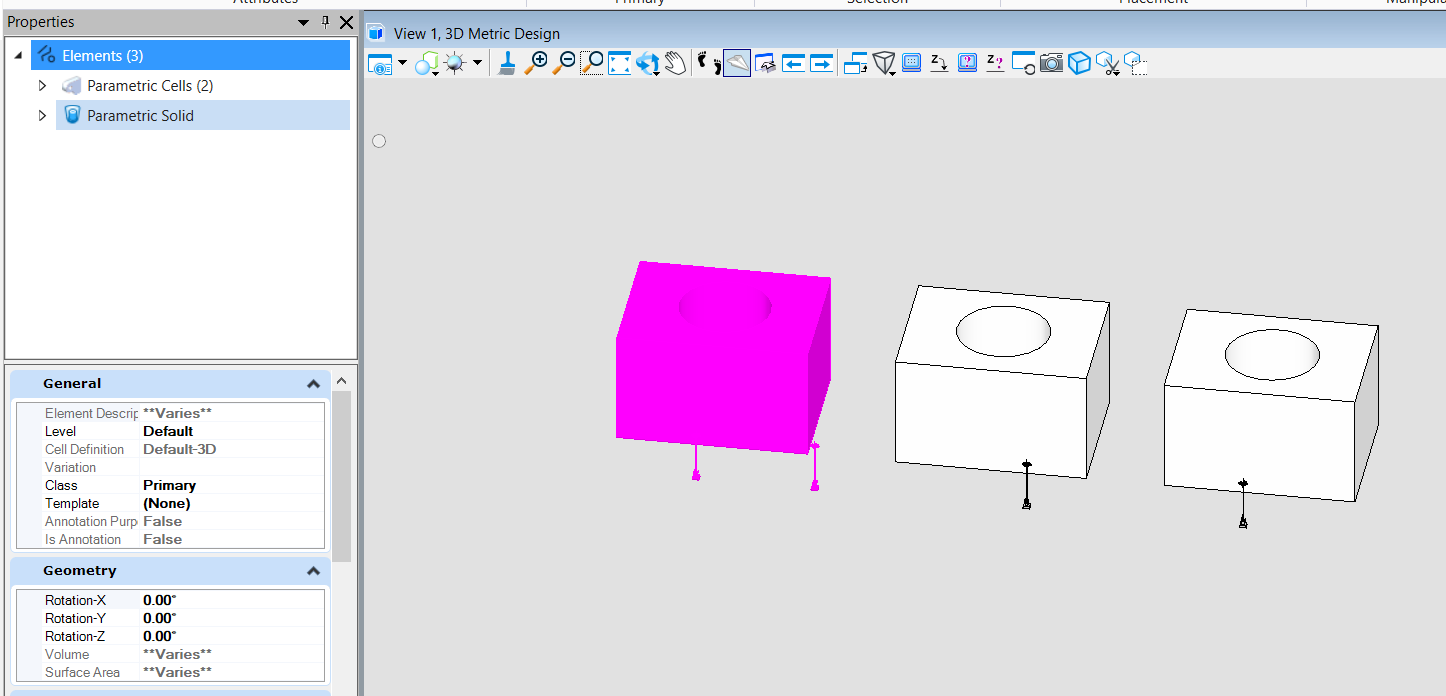<br />**图10 选择集选择状态**<br />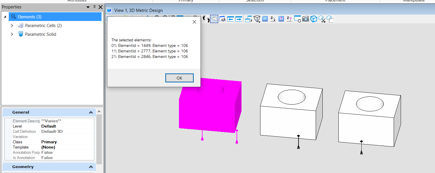<br />**图11 选择集遍历结果**
移除选择集中的元素
当我们在选择集中获得到一些不符合最终需求的元素时,我们可以首先将不符合需求的元素筛选出来,而后再将元素移出选择集。
public static void ModifyElemsInSelection1(string unparsed)//Case:DistinguishNestingElement{DgnModel dgnModel = Session.Instance.GetActiveDgnModel();//获得当前激活的模型ElementAgenda agenda = new ElementAgenda();//声明元素容器SelectionSetManager.BuildAgenda(ref agenda);//从当前选择集中获得元素for (uint i = 0; i < agenda.GetCount(); i++)//遍历选择集中的所有元素{if (agenda.GetEntry(i).ElementType == MSElementType.Solid)//通过元素类型为Solid筛选出对应元素{SelectionSetManager.RemoveElement(agenda.GetEntry(i), dgnModel);//移除选择集中元素类型为Solid的元素}}}
在本案例中,我们首先使用框选的方式选中了参数化实体与普通实体,在代码中我们对元素类型为普通实体的元素进行过滤,对其进行移出选择集的操作,所得结果如下。<br />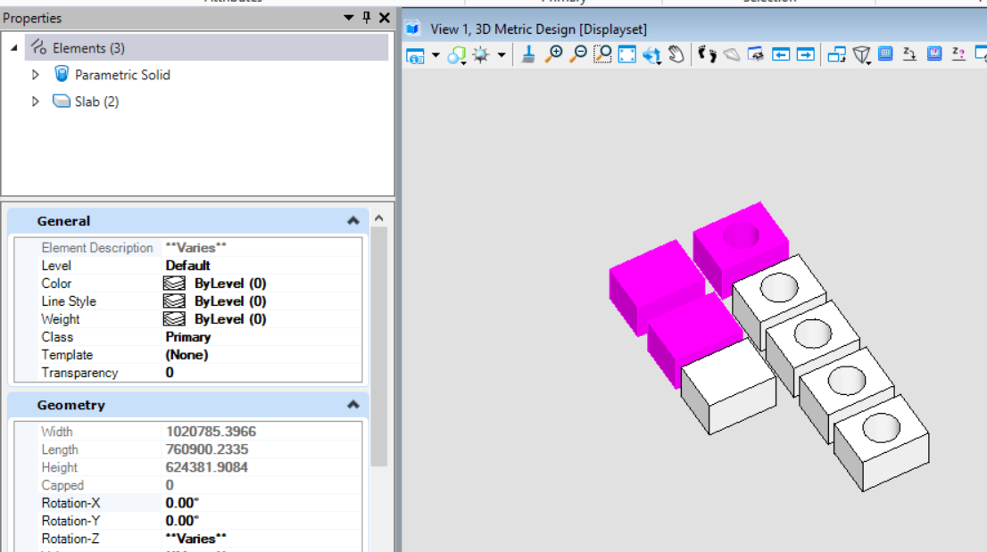<br />**图12 代码执行前**<br />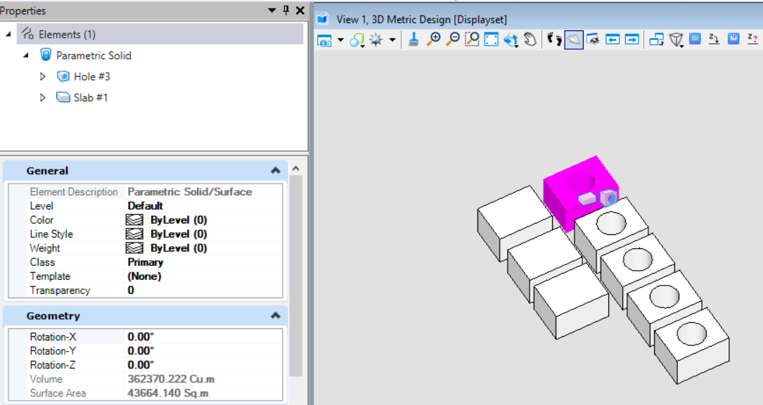<br />**图13 代码执行结果**
倒置选择集中的元素
当我们需要选择大部分而排除小部分相同属性的元素时,若选择大部分元素时,则十分浪费时间,那么如果我们可以选择小部分元素,对该属性元素进行反选,那么则会大幅度提高效率。 <br /> SelectionSetManager.InvertElement( )用于对相同属性类型的元素执行反向倒置选择的操作,即当模型中相同属性的元素为未被选中状态,则执行该方法后该类元素变为选中状态,反之则反。
public static void ModifyElemsInSelection2(string unparsed)//Case:DistinguishNestingElement{DgnModel dgnModel = Session.Instance.GetActiveDgnModel();//获得当前激活的模型ModelElementsCollection elems = dgnModel.GetGraphicElements();//获得当前模型中的所有图形元素foreach (Element elem in elems)//遍历选择集中的所有元素{if (elem.ElementType == MSElementType.Solid)//通过元素类型为Solid筛选出对应元素{SelectionSetManager.InvertElement(elem, dgnModel);//倒置元素类型为Solid的元素}}}
在本案例中,首先在模型中选择了部分参数化实体与普通实体,在执行代码后,对于条件过滤中的普通实体执行选择集倒置操作,因此原本被选中的普通实体变为未选中状态,而参数化实体保持不变。<br />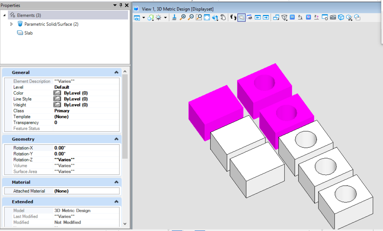<br />**图14 代码执行前**<br />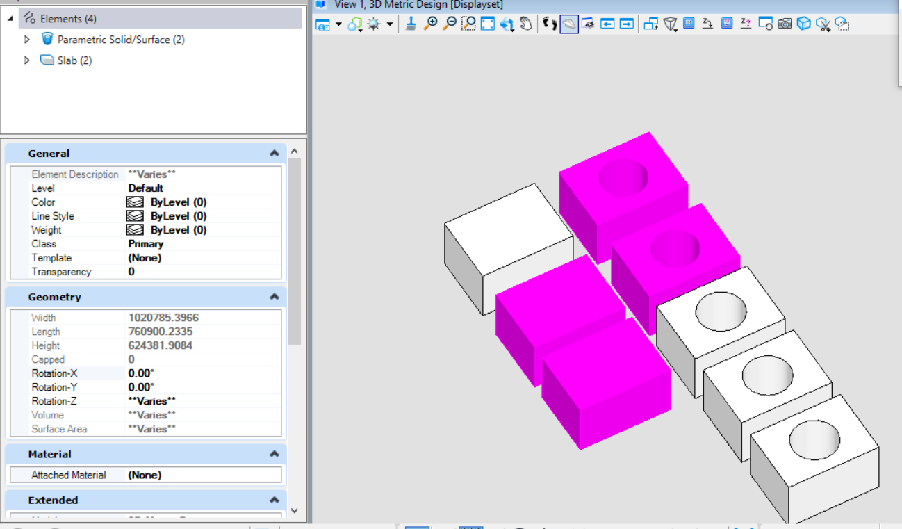<br />**图15 代码执行结果**
替换选择集中的元素
当我们在做管线设计时,如果发现管线某个位置与结构或建筑设计的构件存在碰撞,需要高亮由多个元素构成的整条管线,那么就有可能涉及到将选择的部分构件替换为其他构件。 <br /> SelectionSetManager.ReplaceWithElement( )方法主要用于将选择集中的元素集替换为其他元素,其表现于剔除选择集中的元素并添加用于替换的元素到选择集中。
public static void ModifyElemsInSelection3(string unparsed)//Case:DistinguishNestingElement{DgnModel dgnModel = Session.Instance.GetActiveDgnModel();//获得当前激活的模型double uorPerMas = Session.Instance.GetActiveDgnModel().GetModelInfo().UorPerMaster;//分辨率单位转换为主单位ElementAgenda agenda = new ElementAgenda();//声明元素容器SelectionSetManager.BuildAgenda(ref agenda);//从当前选择集中获得元素if (agenda.GetCount() > 0){DisplayableElement displayableElem = agenda.GetEntry(0) as DisplayableElement;//获得选择集元素对应的父类元素displayableElem.GetTransformOrigin(out DPoint3d elemLoc);//从该父类中获得选中元素的定位坐标EllipseElement ellipse = new EllipseElement(dgnModel, null, elemLoc, 10 * uorPerMas, 5 * uorPerMas, DMatrix3d.Identity);//声明椭圆元素ellipse.AddToModel();//将椭圆元素添加到模型中BentleyStatus status = SelectionSetManager.ReplaceWithElement(ellipse, dgnModel);//将该元素的选中状态替换为椭圆选中}}
在本案例中,首先创建了一个椭圆元素,然后将椭圆元素放置在选择集中索引为0的插入点处,并且将选择集中的元素替换为新创建的椭圆元素。<br />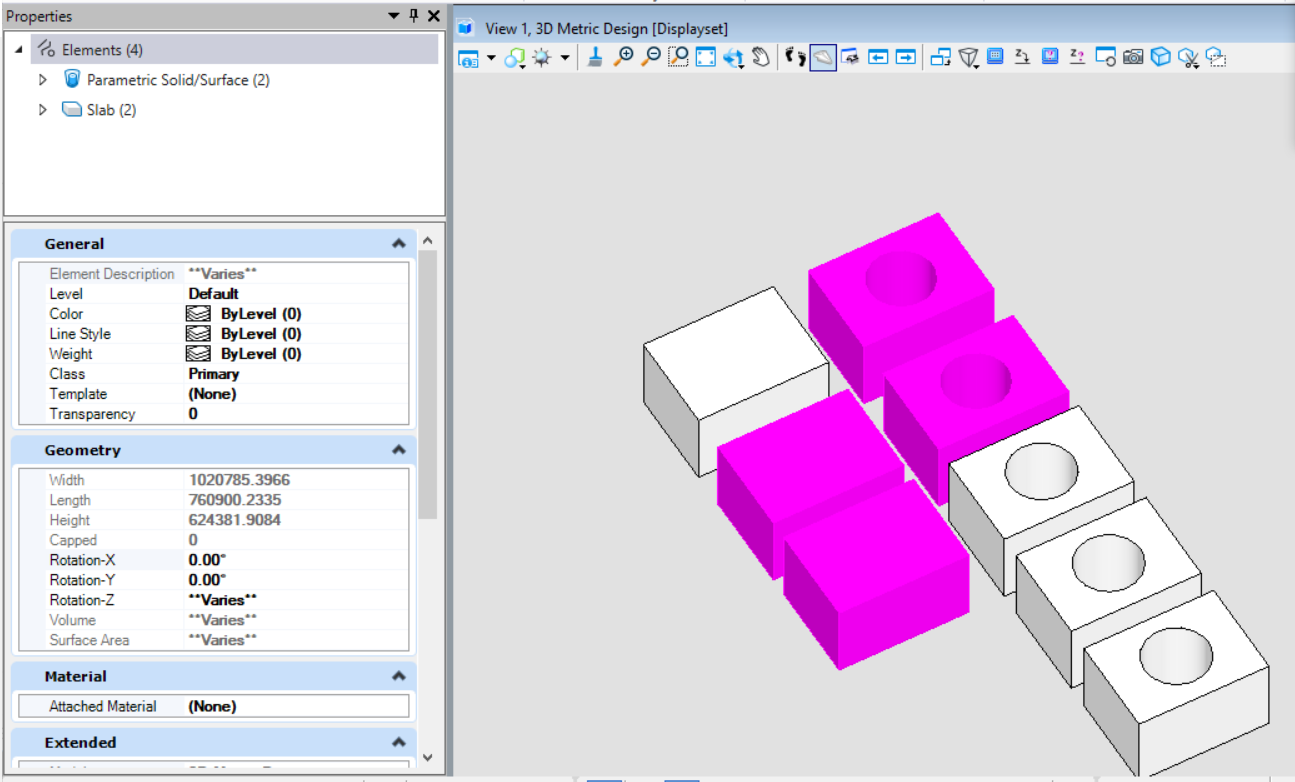<br />**图16 代码执行前**<br />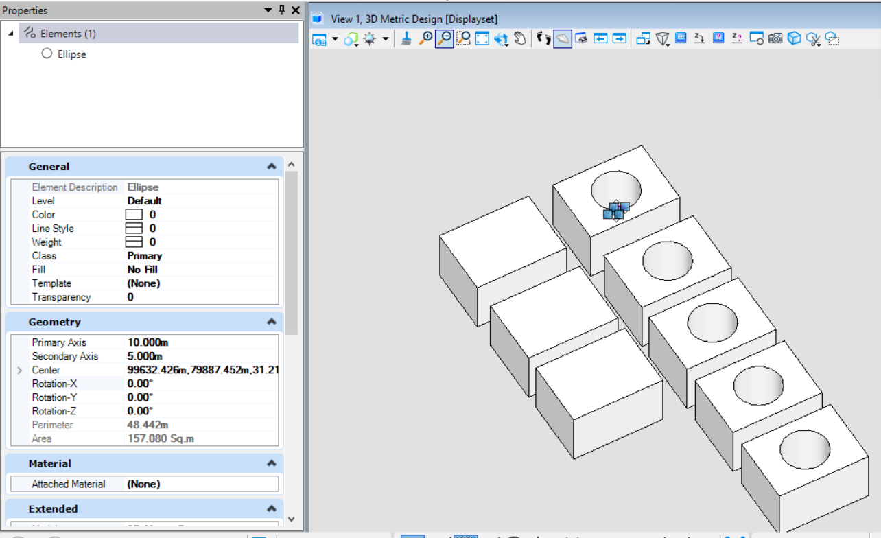<br />**图17 代码执行后**
添加选择集中的元素
若我们需要通过代码的方式获得模型中指定属性的元素集,除了使用MicroStation内置的选择集,我们也可以根据过滤条件筛选出符合要求的元素集,并添加到选择集中供下一步操作。SelectionSetManager.AddElement( )的功能为将元素添加到选择集中。
public static void AddElemsInSelection(string unparsed)//Case:ElementType{DgnModel dgnModel = Session.Instance.GetActiveDgnModel();//获得当前激活的模型ElementAgenda agenda = new ElementAgenda();//声明元素容器SelectionSetManager.EmptyAll();//清空选择集(主要为了防止因前期选择部分元素造成的选择集项目混乱)ModelElementsCollection elems = dgnModel.GetGraphicElements();//获得当前模型中的所有图形元素foreach (Element elem in elems)//遍历模型中的所有元素{if (elem.ElementType == MSElementType.Solid)//通过元素类型为Solid筛选出对应元素{SelectionSetManager.AddElement(elem, dgnModel);//将筛选后的元素写入模型}}}
在本案例中,首先对选择集进行清空操作,以防若选择集中存在元素造成误导,然后对模型中的元素进行遍历,将元素属性为普通实体的元素添加到选择集中。<br />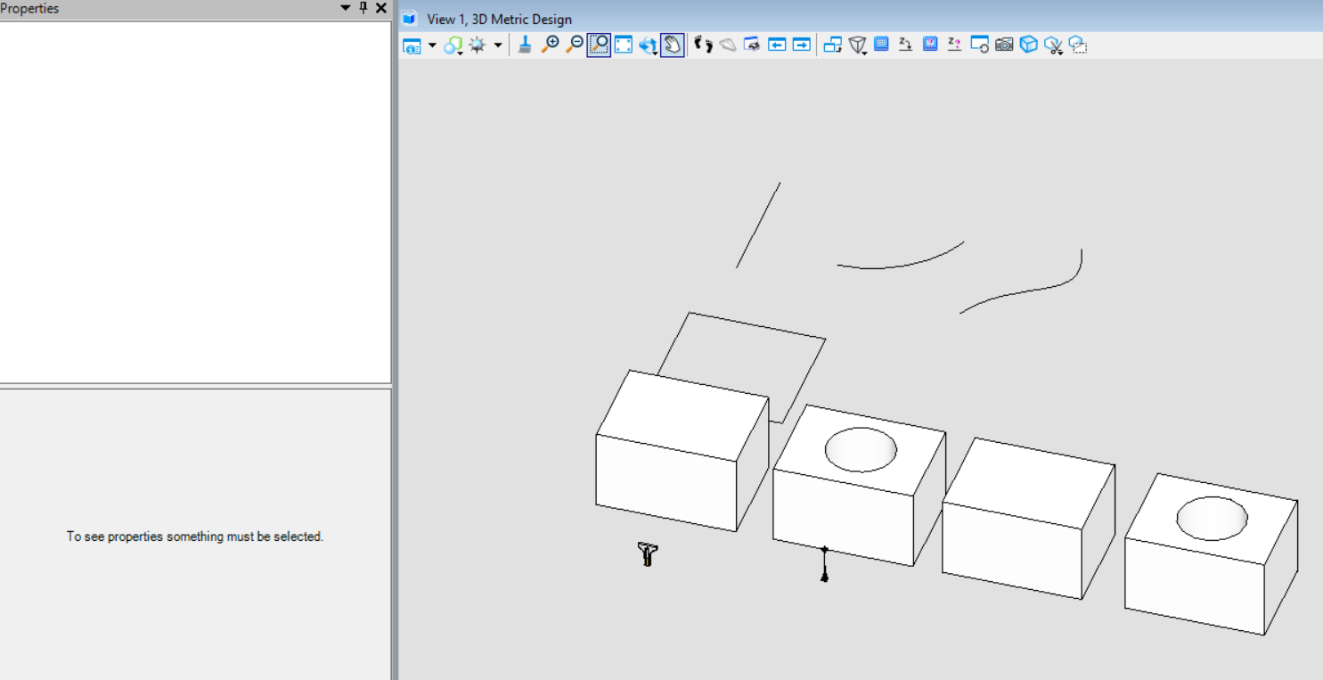<br />**图18 代码执行前**<br />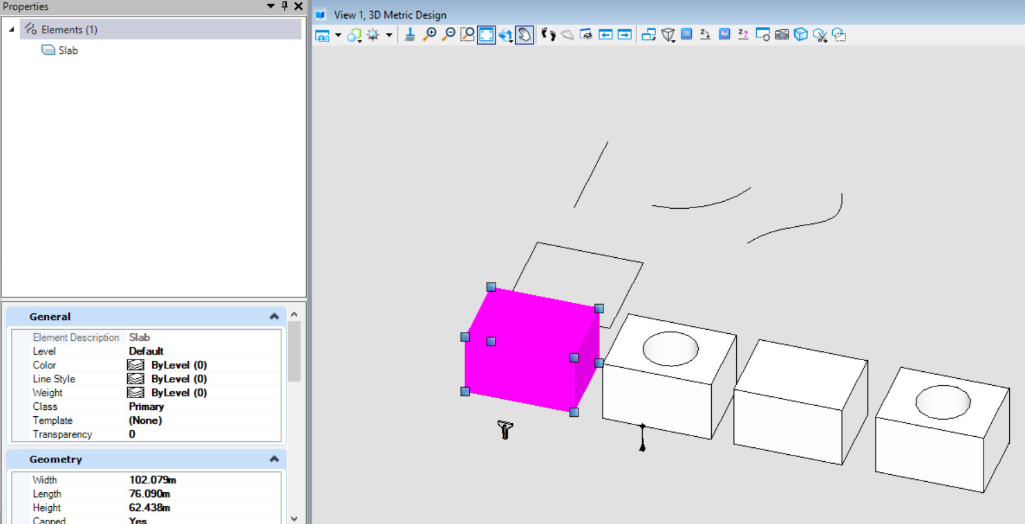<br />**图19 代码执行后**
扫描使用方法介绍
若我们需要根据元素自身或工程属性进行遍历检索,随着模型中元素数量的增多往往会大幅度增加遍历所需要的时间。而扫描工具不仅可以规定扫描区域,也可以指定遍历元素的类型,从而将原本模型中的全部元素的检索变为指定区域,指定元素类型的检索,大幅度提高效率。
public static void FilterByScanCriteria(string unparsed)//Case:ScanCriteriaCase{DgnModel dgnModel = Session.Instance.GetActiveDgnModel();//获得当前激活的模型double uorPerMas = Session.Instance.GetActiveDgnModel().GetModelInfo().UorPerMaster;//分辨率单位转换为主单位ScanCriteria sc = new ScanCriteria();//声明扫描标准sc.SetModelRef(dgnModel);//设置扫描目标模型sc.SetModelSections(DgnModelSections.GraphicElements);//设置扫描部分(本案例中仅扫描图形元素)BitMask elemTypeMask = new BitMask(false);//声明可变位数组elemTypeMask.Capacity = 128;//设置数组容量elemTypeMask.ClearAll();// Element Type Number - 1 = BitMask IndexelemTypeMask.SetBit(18, true); // Element Type = Solid (Not SmartSolid), or (int)MSElementType.Solid - 1 设置筛选元素类型sc.SetElementTypeTest(elemTypeMask);//将可变位数组应用于扫描标准ScanRange range = new ScanRange((long)(99439.621 * uorPerMas), (long)(79738.341 * uorPerMas), 0, (long)(99701.215 * uorPerMas), (long)(79946.173 * uorPerMas), 0);//设置扫描范围sc.SetRangeTest(range);//将扫描范围应用于扫描标准 注:若无范围要求不进行该项设置即可string result = "The result of scan is:\n";//声明字符串ScanDelegate scanDelegate = (Element elem, DgnModelRef modelRef) =>//声明扫描委托{//若扫描到符合条件的目标后执行的操作result = result + "ElmentId = " + elem.ElementId + ", element type = " + elem.TypeName + '\n';return StatusInt.Success;//返回成功};sc.Scan(scanDelegate);//执行扫描MessageBox.Show(result);//将字符串结果输出到对话框}
代码中首先声明了扫描标准,并设置扫描模型中图形元素,设置扫描元素类型及扫描区域后声明扫描委托,获得符合条件的元素。在本案例中,我们扫描的是图中Shape元素围城的区域,从最终的输出结果表明,扫描会在设置的范围框中针对元素属性条件为普通实体进行元素的过滤,最终获得指定区域内属性为普通实体的元素集合。<br />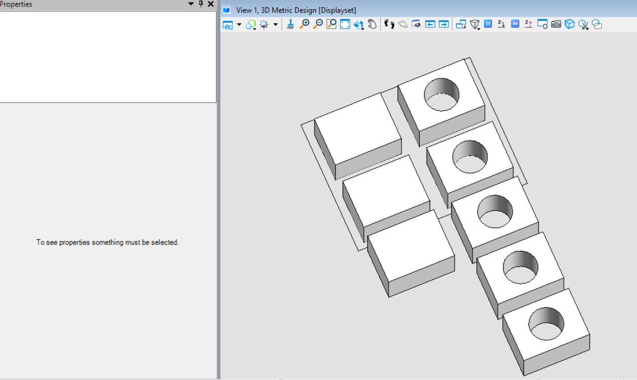<br />**图20 代码执行前**<br />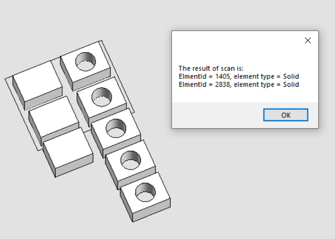<br />**图21 代码执行后**
围栅使用方法介绍
使用元素创建围栅
该方法类似于使用MicroStation软件中的选择元素建立围栅的方法,确定构造围栅的元素后,他会根据选取的元素构造出一个垂直于该元素的三维围栅体,获得该区域内的所有元素。
图22 MicroStation中使用元素建立围栅功能
public static void CreateFenceByElement(string unparsed)//Case:FenceClipByElement{DgnModelRef dgnModelRef = Session.Instance.GetActiveDgnModelRef();//获得当前的模型空间/参照空间 注:DgnModelRef是一个基类,DgnModel和DgnAttachment都派生于这个基类DgnModel dgnModel = Session.Instance.GetActiveDgnModel();//获得当前激活的模型空间Viewport view = Session.GetActiveViewport();//获得当前视图信息double uorPerMas = Session.Instance.GetActiveDgnModel().GetModelInfo().UorPerMaster;//分辨率单位转换为主单位#region Create complex shape elementDPoint3d p1 = new DPoint3d(-10*uorPerMas,0,0);//声明线串元素端点DPoint3d p2 = new DPoint3d(-10 * uorPerMas, 260*uorPerMas,0);DPoint3d p3 = new DPoint3d(110*uorPerMas,260*uorPerMas,0);DPoint3d p4 = new DPoint3d(110*uorPerMas,110*uorPerMas,0);DPoint3d[] pos = { p1,p2,p3,p4 };//声明端点集LineStringElement lineString = new LineStringElement(dgnModel,null,pos);//声明线串元素DPoint3d centerPo = new DPoint3d(0,100*uorPerMas,0);//声明弧元素的圆心ArcElement arc = new ArcElement(dgnModel,null, centerPo,110*uorPerMas,110*uorPerMas,DMatrix3d.Identity, 0, -Angle.PI.Radians / 2);//声明弧元素ComplexShapeElement complexShape = new ComplexShapeElement(dgnModel,null);//声明复杂形元素complexShape.AddComponentElement(lineString);//将子构件添加到复杂元素中complexShape.AddComponentElement(arc);complexShape.AddComponentComplete();//子构件添加完成#endregionif (StatusInt.Success == FenceManager.DefineByElement(complexShape, view))//使用元素围成的区域声明围栅{FenceParameters fenceParams = new FenceParameters(dgnModelRef, DTransform3d.Identity);//声明围栅信息FenceManager.InitFromActiveFence(fenceParams, false, false, FenceClipMode.None);/** 使用围栅信息初始化围栅* fenceParameters:围栅信息* overlap:若需囊括部分包含的元素则输入true* doClip:若需修剪操作则输入true* allowClipFlag:若需要在原始元素上剪切则输入FenceClipMode.Original,若需要在新声明的元素上剪切则输入FenceClipMode.Copy*/ElementAgenda eAgenda = new ElementAgenda();//声明元素容器DgnModelRef[] modelRefList = new DgnModelRef[1];//设置需要声明围栅的模型空间modelRefList[0] = dgnModelRef;//设置模型空间FenceManager.BuildAgenda(fenceParams, eAgenda, modelRefList, false, false, false);/** 使用围栅信息获得符合要求的元素集* fenceParameters:围栅信息* elementAgenda:符合要求的元素集* modelRefList:声明围栅的模型空间* modifyOrig:是否修改原始元素* allowLocked:是否允许锁定元素* callAsynch:是否需要调用异步*/string result = "Result:\n";//声明字符串for (uint i = 0; i < eAgenda.GetCount(); i++)//遍历元素容器中的元素{Element element = eAgenda.GetEntry(i);//获得元素容器中的元素result = result + "ElementId = " + element.ElementId + '\n';//将元素ID写入模型}result = result + "Total count: " + eAgenda.GetCount();//输出元素个数MessageBox.Show(result);//将字符串输出到对话框中}}
在文件名为FenceClipByElement的案例中,预先建立了四个实体元素,然后我们首先使用形元素创建围栅的轮廓并定义围栅,规定只有围栅完全包含元素才能获取元素(InitFromActiveFence( )中第二个参数控制),最终获得完全包含在围栅内的元素。<br />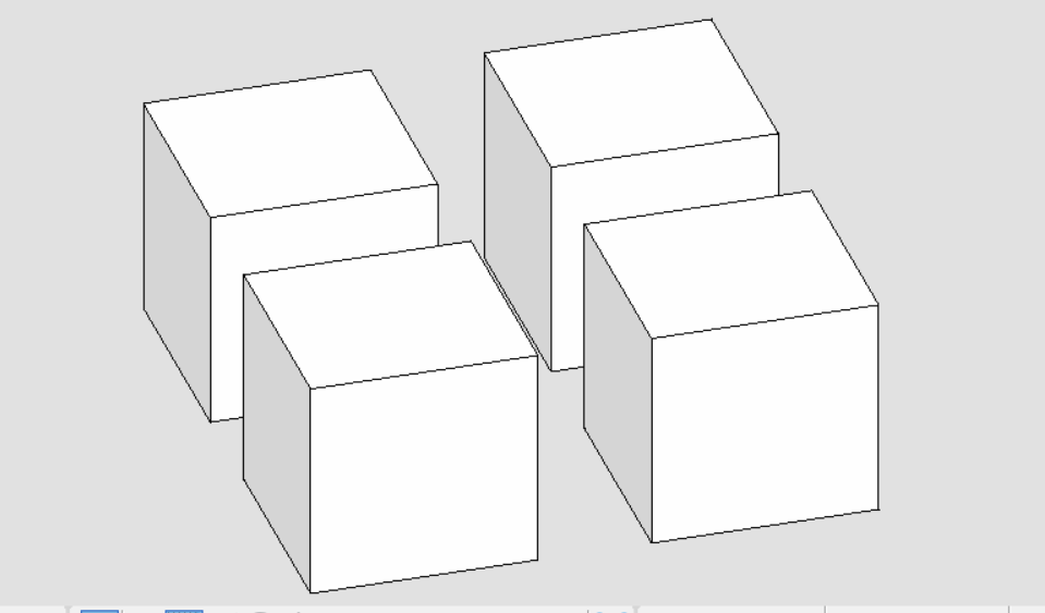<br />**图23 代码执行前**<br />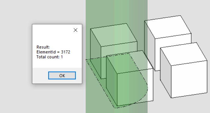<br />**图24 围栅检索元素结果**
使用点集创建围栅
该方法类似于MicroStation中围栅功能中通过绘制创建围栅的方法。与前者不同的是,前者视角对于围栅的建立没有影响,他只根据创建元素的垂直法线建立围栅;而该方法高度依赖视角的变化,若视角不同,则获取到围栅内元素的结果也会不同。<br />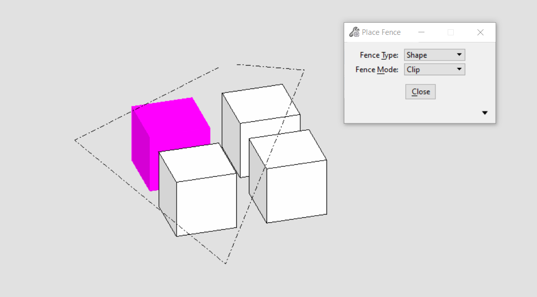<br />**图25 MicroStation中使用绘制方式建立围栅功能**
public static void CreateFenceByPoints(string unparsed)//Case:FenceClipByPoints{DgnModelRef dgnModelRef = Session.Instance.GetActiveDgnModelRef();//获得当前的模型空间/参照空间 注:DgnModelRef是一个基类,DgnModel和DgnAttachment都派生于这个基类Viewport view = Session.GetActiveViewport();//获得当前视图信息double uorPerMas = Session.Instance.GetActiveDgnModel().GetModelInfo().UorPerMaster;//分辨率单位转换为主单位DPoint3d p1 = new DPoint3d(-10 * uorPerMas, 0,-130 * uorPerMas);//声明围栅坐标点DPoint3d p2 = new DPoint3d(300 * uorPerMas, 0, -130 * uorPerMas);DPoint3d p3 = new DPoint3d(300 * uorPerMas, 0,-10 * uorPerMas);DPoint3d p4 = new DPoint3d(130 * uorPerMas,0, -10 * uorPerMas);DPoint3d p5 = new DPoint3d(130 * uorPerMas, 0, 130 * uorPerMas);DPoint3d p6 = new DPoint3d(-10 * uorPerMas, 0, 130 * uorPerMas);DPoint3d[] pos = { p1, p2, p3, p4,p5,p6 };//使用端点声明端点集if (StatusInt.Success == FenceManager.DefineByPoints(pos, view))//使用端点声明{FenceParameters fenceParams = new FenceParameters(dgnModelRef, DTransform3d.Identity);//声明围栅信息FenceManager.InitFromActiveFence(fenceParams, true, false, FenceClipMode.None);//使用围栅信息初始化围栅ElementAgenda eAgenda = new ElementAgenda();//声明元素容器DgnModelRef[] modelRefList = new DgnModelRef[1];//设置需要声明围栅的模型空间modelRefList[0] = dgnModelRef;//设置模型空间FenceManager.BuildAgenda(fenceParams, eAgenda, modelRefList, false, false, false);//使用围栅信息获得符合要求的元素集string result = "Result:\n";//声明字符串for (uint i = 0; i < eAgenda.GetCount(); i++)//遍历元素容器中的元素{Element element = eAgenda.GetEntry(i);//获得元素容器中的元素result = result + "ElementId = " + element.ElementId + '\n';//将元素ID写入模型}result = result + "Total count: " + eAgenda.GetCount();//输出元素个数MessageBox.Show(result);//将字符串输出到对话框中}}
在文件名为FenceClipByPoints的案例中,上方四个实体元素是参照其他模型的元素,下方四个实体元素为该模型中的元素,首先使用点集构建出围栅轮廓,然后围栅会以视图方向为围栅法线方向构建围栅并获得囊括在围栅内的元素集合。在定义围栅时InitFromActiveFence( )中第二个参数设为真,可以看到就算是部分囊括的元素同样会被添加到元素集合中。<br />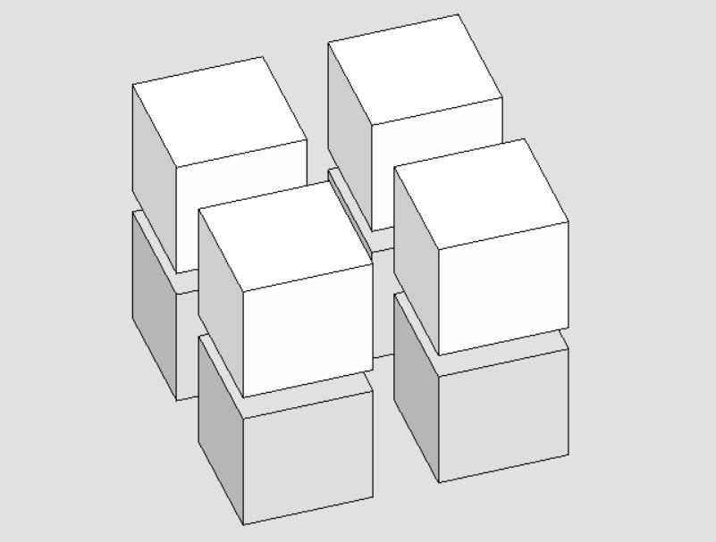<br />**图26 代码执行前**<br />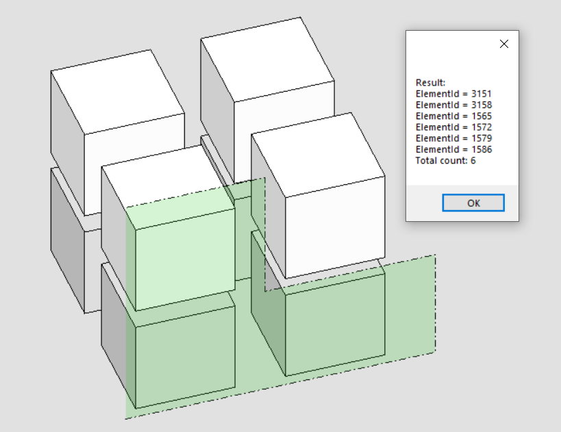<br />**图27 围栅检索元素结果1**<br />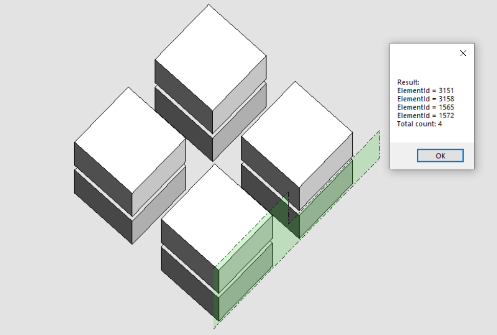<br />**图28 围栅检索元素结果2**
检索并复制围栅内元素
当我们需要对围栅内的元素进行复制,便需要首先创建围栅,而后执行元素的复制操作。需要注意的是,在本案例中使用到的围栅内元素复制方法,不仅适用于模型内元素,同样适用于参考模型元素。
public static void CopyFenceByPoints(string unparsed)//Case:FenceClipByPoints{DgnModelRef dgnModelRef = Session.Instance.GetActiveDgnModelRef();//获得当前的模型空间/参照空间 注:DgnModelRef是一个基类,DgnModel和DgnAttachment都派生于这个基类Viewport view = Session.GetActiveViewport();//获得当前视图信息double uorPerMas = Session.Instance.GetActiveDgnModel().GetModelInfo().UorPerMaster;//分辨率单位转换为主单位DPoint3d p1 = new DPoint3d(-10 * uorPerMas, 0, -130 * uorPerMas);//声明围栅坐标点DPoint3d p2 = new DPoint3d(300 * uorPerMas, 0, -130 * uorPerMas);DPoint3d p3 = new DPoint3d(300 * uorPerMas, 0, -10 * uorPerMas);DPoint3d p4 = new DPoint3d(130 * uorPerMas, 0, -10 * uorPerMas);DPoint3d p5 = new DPoint3d(130 * uorPerMas, 0, 130 * uorPerMas);DPoint3d p6 = new DPoint3d(-10 * uorPerMas, 0, 130 * uorPerMas);DPoint3d[] pos = { p1, p2, p3, p4, p5, p6 };//使用端点声明端点集if (StatusInt.Success == FenceManager.DefineByPoints(pos, view))//使用端点声明{FenceParameters fenceParams = new FenceParameters(dgnModelRef, DTransform3d.Identity);//声明围栅信息FenceManager.InitFromActiveFence(fenceParams, true, false, FenceClipMode.Copy);//使用围栅信息初始化围栅ElementAgenda eAgenda = new ElementAgenda();//声明元素容器DgnModelRef[] modelRefList = new DgnModelRef[1];//设置需要声明围栅的模型空间modelRefList[0] = dgnModelRef;//设置模型空间FenceManager.BuildAgenda(fenceParams, eAgenda, modelRefList, false, false, false);//使用围栅信息获得符合要求的元素集for (uint i = 0; i < eAgenda.GetCount(); i++)//遍历元素容器中的元素{using (ElementCopyContext copyContext = new ElementCopyContext(dgnModelRef))//复制元素{Element element = eAgenda.GetEntry(i);//获得元素容器中的元素copyContext.DoCopy(element);//将元素复制到指定模型中}}}}
在文件名为FenceClipByPoints的案例中,上方四个实体元素是引用参照其他模型中的元素,下方四个实体元素为该模型中的元素,使用点集创建围栅的方式,对围栅内的元素进行复制操作,代码执行后可以发现无论是模型中还是参照中的元素都被顺利复制到当前模型中。注意:复制元素的目标模型由ElementCopyContext copyContext = new ElementCopyContext(dgnModelRef)中的入参模型确定,若您需要复制到其他模型中,修改该入参即可实现。<br />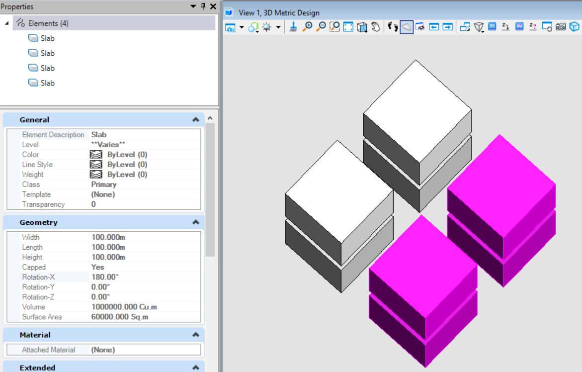<br />**图29 代码执行前**<br />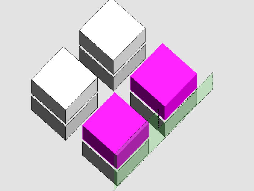<br />**图30 围栅创建结果**<br />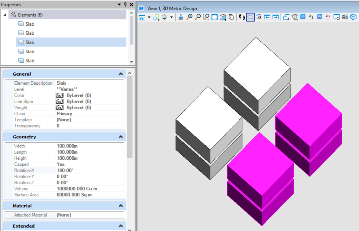<br />**图31 元素复制结果**
使用围栅拉伸元素
该方法类似于MicroStation中修改围栅中的拉伸功能,该功能可以对元素以拉伸端点的方式对元素进行拉伸操作。需要注意的是,该方法无法对参照模型中的元素执行拉伸操作。<br />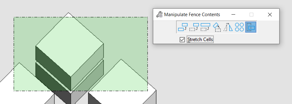<br />**图32 MicroStation中围栅拉伸功能**
public static void StretchElementByFence(string unparsed)//Case:FenceClipByPoints{DgnModelRef dgnModelRef = Session.Instance.GetActiveDgnModelRef();//获得当前的模型空间/参照空间 注:DgnModelRef是一个基类,DgnModel和DgnAttachment都派生于这个基类Viewport view = Session.GetActiveViewport();//获得当前视图信息double uorPerMas = Session.Instance.GetActiveDgnModel().GetModelInfo().UorPerMaster;//分辨率单位转换为主单位DPoint3d p1 = new DPoint3d(-10 * uorPerMas, 0, -130 * uorPerMas);//声明围栅坐标点DPoint3d p2 = new DPoint3d(-10 * uorPerMas, 0, 200 * uorPerMas);DPoint3d p3 = new DPoint3d(50 * uorPerMas, 0, 200 * uorPerMas);DPoint3d p4 = new DPoint3d(50 * uorPerMas, 0, -130 * uorPerMas);DPoint3d[] pos = { p1, p2, p3, p4 };//使用端点声明端点集if (StatusInt.Success == FenceManager.DefineByPoints(pos, view))//使用端点声明{FenceParameters fenceParams = new FenceParameters(dgnModelRef, DTransform3d.Identity);//声明围栅信息FenceManager.InitFromActiveFence(fenceParams, true, false, FenceClipMode.None);//使用围栅信息初始化围栅ElementAgenda eAgenda = new ElementAgenda();//声明元素容器DgnModelRef[] modelRefList = new DgnModelRef[1];//设置需要声明围栅的模型空间modelRefList[0] = dgnModelRef;//设置模型空间FenceManager.BuildAgenda(fenceParams, eAgenda, modelRefList, false, false, false);//使用围栅信息获得符合要求的元素集 .for (uint i = 0; i < eAgenda.GetCount(); i++)//遍历元素容器中的元素{Element element = eAgenda.GetEntry(i);//获得元素容器中的元素DPoint3d po = new DPoint3d(-50*uorPerMas,0,0);//声明坐标点,在本文中用于表明移动的值,具体可参考元素变换课程相关内容StatusInt status= FenceManager.StretchElement(fenceParams, element,DTransform3d.FromTranslation(po),FenceStretchFlags.None);/** 使用围栅对元素拉伸 注:视图对拉伸结果也有影响* fenceParameters:围栅信息* element:围栅内拉伸的元素* transform:变换信息* stretchFlags:围栅拉伸风格。若为Cells,则可拉伸用户声明的单元组件*/if (status==StatusInt.Success)//判断是否拉伸成功{element.AddToModel();//将拉伸结果写入模型}}}}
在文件名为FenceClipByPoints的案例中,上方四个实体元素是引用参照其他模型中的元素,下方四个实体元素为该模型中的元素。首先仍是使用点集创建围栅,然后在对拉伸方向及大小进行设定后使用FenceManager.StretchElement( )对元素进行拉伸,在本案例中是对元素端点执行X轴负方向进行50单位拉伸的操作。最终获得结果如图所示,从结果上看,参照到模型中的元素无法执行拉伸操作,本模型内的元素则不受限制。<br />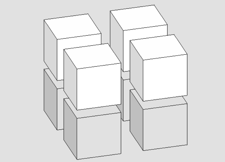<br />**图33 代码执行前**<br />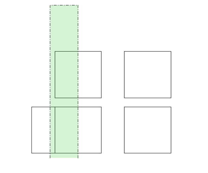<br />**图34 围栅建立结果**<br />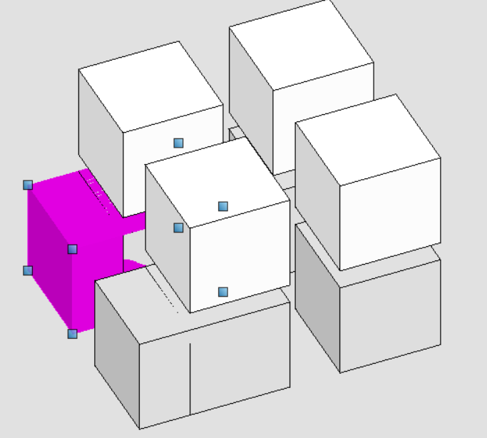<br />**图35 围栅拉伸结果**
使用围栅剪切元素
该方法与MicroStation中使用围栅剪切元素的功能一致,用于对元素执行剪切操作,它最大的优势在于无论是什么元素,都可以被顺利剪切。当前,在使用围栅剪切后,可能会丢失部分数据,比如说挂接的工程属性,同时,也有可能破坏原本元素内部的数据。
图36 MicroStation中围栅切割功能
public static void ClipElementByFence(string unparsed)//Case:FenceClipByPoints{DgnModelRef dgnModelRef = Session.Instance.GetActiveDgnModelRef();//获得当前的模型空间/参照空间 注:DgnModelRef是一个基类,DgnModel和DgnAttachment都派生于这个基类DgnModel dgnModel = Session.Instance.GetActiveDgnModel();//获得当前激活的模型空间Viewport view = Session.GetActiveViewport();//获得当前视图信息double uorPerMas = Session.Instance.GetActiveDgnModel().GetModelInfo().UorPerMaster;//分辨率单位转换为主单位DPoint3d p1 = new DPoint3d(-10 * uorPerMas, 0, -130 * uorPerMas);//声明围栅坐标点DPoint3d p2 = new DPoint3d(-10 * uorPerMas, 0, 200 * uorPerMas);DPoint3d p3 = new DPoint3d(50 * uorPerMas, 0, 200 * uorPerMas);DPoint3d p4 = new DPoint3d(50 * uorPerMas, 0, -130 * uorPerMas);DPoint3d[] pos = { p1, p2, p3, p4 };//使用端点声明端点集ShapeElement shape = new ShapeElement(dgnModel, null,pos);//声明形元素if (StatusInt.Success == FenceManager.DefineByElement(shape, view))//使用图形建立围栅{FenceParameters fenceParams = new FenceParameters(dgnModelRef, DTransform3d.Identity);//声明围栅信息FenceManager.InitFromActiveFence(fenceParams, true, true, FenceClipMode.Copy);//使用围栅信息初始化围栅ElementAgenda eAgenda = new ElementAgenda();//声明元素容器DgnModelRef[] modelRefList = new DgnModelRef[1];//设置需要声明围栅的模型空间modelRefList[0] = dgnModelRef;//设置模型空间FenceManager.BuildAgenda(fenceParams, eAgenda, modelRefList, false, false, false);//使用围栅信息获得符合要求的元素集for (uint i = 0; i < eAgenda.GetCount(); i++)//遍历元素容器中的元素{ElementAgenda insideElems = new ElementAgenda();//声明元素容器ElementAgenda outsideElems = new ElementAgenda();//声明元素容器Element element = eAgenda.GetEntry(i);//获得元素容器中的元素FenceManager.ClipElement(fenceParams, insideElems, outsideElems, element, FenceClipFlags.Optimized);//对围栅内的元素进行剪切for (uint j = 0; j < outsideElems.GetCount(); j++)//遍历围栅切割后生成的外围元素{using (ElementCopyContext copyContext = new ElementCopyContext(dgnModelRef))//复制元素{Element elemToCopy = outsideElems.GetEntry(j);//获得切割后生成的外围元素copyContext.DoCopy(elemToCopy);//将元素复制到指定模型中}}}}}
在文件名为FenceClipByPoints的案例中,上方四个实体元素是引用参照其他模型中的元素,下方四个实体元素为该模型中的元素。首先使用点集创建了一个围栅,与上面方法不同的是,在初始化围栅时,FenceManager.InitFromActiveFence( )中第三个参数用于控制围栅是否执行剪切惭怍,需要输入真,然后使用FenceManager.ClipElement( )对围栅检索到的元素使用围栅执行切割操作,最后将切割结果写入模型。需要注意的是,对参照模型中的元素使用围栅剪切也可以获得结果。
图37 代码执行前
图38 围栅剪切结果
元素分解
提取元素中多面体几何(Polyface)
该方法主要用于对分解元素为Polyface,它的优势在于无论是什么元素,只要元素中几何部分具有Polyface,他就可以成功获取。
//参考文章:https://communities.bentley.com/communities/other_communities/bdn_other_communities/b/bdn-blog/posts/meshpublic static void BreakElementIntoPolyface(string unparsed)//Case:BreakSolidExample{DgnModel dgnModel = Session.Instance.GetActiveDgnModel();//获取当前的模型空间double uorPerMas = Session.Instance.GetActiveDgnModel().GetModelInfo().UorPerMaster;//分辨率单位转换为主单位#region Create Solid#region Create profileDPoint3d p1 = new DPoint3d(-uorPerMas, uorPerMas, 0);//声明体元素端点DPoint3d p2 = new DPoint3d(uorPerMas, uorPerMas, 0);DPoint3d p3 = new DPoint3d(uorPerMas, -uorPerMas, 0);DPoint3d p4 = new DPoint3d(-uorPerMas, -uorPerMas, 0);DPoint3d[] pos = { p1, p2, p3, p4 };//将面元素端点添加到面元素端点数组中ShapeElement shape = new ShapeElement(dgnModel, null, pos);//声明形元素#endregionDPoint3d origin = DPoint3d.Zero;//声明拉伸基点DVector3d extrudeVector = new DVector3d(uorPerMas, uorPerMas, 10* uorPerMas);//声明拉伸向量SurfaceOrSolidElement solid = SurfaceOrSolidElement.CreateProjectionElement(dgnModel, null, shape, origin, extrudeVector, DTransform3d.Identity, true);//声明实体元素solid.AddToModel();//将拉伸体写入模型#endregionIList<PolyfaceHeader> polyfaces = new List<PolyfaceHeader>();//声明多面体几何列表FacetOptions facetOptions = new FacetOptions();//曲面属性,用于设置生成曲面或曲线弦的属性声明facetOptions.SetDefaults();//属性设置为默认PolyfaceProcessor polyfaceProcessor = new PolyfaceProcessor(ref polyfaces, facetOptions);//声明用于分解多面体几何的处理器polyfaceProcessor.Process(solid); //将需要分解的元素输入处理器中for (int i=0;i<polyfaces.Count;i++)//遍历元素中分解后的多面体几何{List<uint> colorIndex = new List<uint>();//声明颜色索引foreach(DPoint3d po in polyfaces[i].Point)//为了获得该多面体几何的端点个数,对端点进行遍历{if(po.Z<5*uorPerMas)//Z坐标小于5为红色,否则则为蓝色{colorIndex.Add(0x00ff0000);//红色}else{colorIndex.Add(0x000000ff);//蓝色}//关于16进制颜色对照请参考:http://each.sinaapp.com/tools/color.html 格式为:0x00+(去掉#)16进制颜色}polyfaces[i].IntColor = colorIndex;//设置多面体几何的颜色索引值polyfaces[i].ActivateVectorsForIndexing(polyfaces[i]);//设置为激活状态,以便携带所有的数据及索引信息MeshHeaderElement meshElem = new MeshHeaderElement(dgnModel, null, polyfaces[i]);//使用修改后的多面体几何建立网格元素TransformInfo trans = new TransformInfo(DTransform3d.FromTranslation(new DPoint3d(5*uorPerMas,0,0)));//声明变换信息meshElem.ApplyTransform(trans);//对网格元素应用变换meshElem.AddToModel();//将网格元素写入模型}}public class PolyfaceProcessor : ElementGraphicsProcessor{private IList<PolyfaceHeader> m_outputPolyface;private FacetOptions m_options;private DTransform3d m_currentTransform;public PolyfaceProcessor(ref IList<PolyfaceHeader> outputPolyface, FacetOptions options){m_outputPolyface = outputPolyface;m_currentTransform = DTransform3d.Identity;m_options = options;}public override FacetOptions GetFacetOptions(){return m_options;}public override bool ProcessAsBody(bool isCurved){return false;}public override bool ProcessAsFacets(bool isPolyface){return true;}public override BentleyStatus ProcessFacets(PolyfaceHeader meshData, bool filled = false){if (meshData.FacetCount == 0){return BentleyStatus.Error;}PolyfaceHeader header = PolyfaceHeader.New();header.CopyFrom(meshData);header.TwoSided = true;header.Transform(ref m_currentTransform, false);m_outputPolyface.Add(header);return BentleyStatus.Success;}public void Process(Element element){ElementGraphicsOutput.Process(element, this);}public override void AnnounceTransform(DTransform3d transform){if (transform != null){m_currentTransform = transform;}else{m_currentTransform = DTransform3d.Identity;}}public override void AnnounceIdentityTransform(){m_currentTransform = DTransform3d.Identity;}}
在本案例中,首先创建了一个拉伸实体,然后从拉伸实体中获取到其对应的Polyface,然后对Polyface执行端点渐变填充的操作,最后使用Polyface创建出新的元素。<br />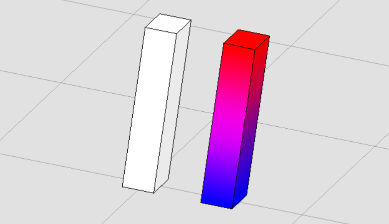<br />**图39 元素生成结果**
提取元素中曲线(CurveVector)
该方法主要用于对分解元素为CurveVector,它的优势在于无论是什么元素,只要元素中几何部分具有CurveVector,他就可以成功获取。
public static void BreakElementIntoCurves(string unparsed)//Case:BreakSolidExample{DgnModel dgnModel = Session.Instance.GetActiveDgnModel();//获取当前的模型空间double uorPerMas = Session.Instance.GetActiveDgnModel().GetModelInfo().UorPerMaster;//分辨率单位转换为主单位#region Create Solid#region Create profileDPoint3d p1 = new DPoint3d(-uorPerMas, uorPerMas, 0);//声明体元素端点DPoint3d p2 = new DPoint3d(uorPerMas, uorPerMas, 0);DPoint3d p3 = new DPoint3d(uorPerMas, -uorPerMas, 0);DPoint3d p4 = new DPoint3d(-uorPerMas, -uorPerMas, 0);DPoint3d[] pos = { p1, p2, p3, p4 };//将面元素端点添加到面元素端点数组中ShapeElement shape = new ShapeElement(dgnModel, null, pos);//声明形元素#endregionDPoint3d origin = DPoint3d.Zero;//声明拉伸基点DVector3d extrudeVector = new DVector3d(uorPerMas, uorPerMas, 10 * uorPerMas);//声明拉伸向量SurfaceOrSolidElement solid = SurfaceOrSolidElement.CreateProjectionElement(dgnModel, null, shape, origin, extrudeVector, DTransform3d.Identity, true);//声明实体元素solid.AddToModel();//将拉伸体写入模型#endregionIList<CurveVector> curves = new List<CurveVector>();//声明多面体几何列表CurveProcessor curveProcessor = new CurveProcessor(ref curves);//声明用于分解曲线几何的处理器curveProcessor.Process(solid); //将需要分解的元素输入处理器中List<CurveVector> curvesList = new List<CurveVector>();//声明几何图元列表for (int i = 0; i < curves.Count; i++)//遍历元素中分解后的曲线几何{Element subElem = DraftingElementSchema.ToElement(dgnModel, curves[i], null);//将几何转换成对应的元素subElem.AddToModel();//将元素写入模型if (subElem.ElementType==MSElementType.LineString)//判断转换后的元素是否为线串{ComplexShapeElement complexShape = new ComplexShapeElement(dgnModel,null);//声明复杂形元素(因为对于线串元素不一定为闭合,有可能无法围城封闭图形,故使用建立shape的形式闭合几何图形)complexShape.AddComponentElement(subElem);//将线串元素添加到shape元素中complexShape.AddComponentComplete();//添加元素完成CurveVector shapeCurve = complexShape.GetCurveVector();//获得shape的封闭图形CurveVector curveWithFillets = shapeCurve.CloneWithFillets(0.1 * uorPerMas);//对获得的几何图元做倒角处理curvesList.Add(curveWithFillets);//将几何图元添加到列表中}}BentleyStatus result = Create.BodyFromLoft(out SolidKernelEntity entityOut, curvesList.ToArray(), curvesList.Count, curvesList.ToArray(), 0, dgnModel, false, false);//声明扫掠体Convert1.BodyToElement(out Element solidElem, entityOut, null, dgnModel);//将实体转换为元素solidElem.AddToModel();//将元素写入模型空间}public class CurveProcessor : ElementGraphicsProcessor{private IList<CurveVector> m_outputCurve;private DTransform3d m_currentTransform;public CurveProcessor(ref IList<CurveVector> outputCurve){m_outputCurve = outputCurve;m_currentTransform = DTransform3d.Identity;}public override bool ProcessAsBody(bool isCurved){return false;}public override bool ProcessAsFacets(bool isPolyface){return false;}public override BentleyStatus ProcessCurveVector(CurveVector curves, bool isFilled = false){CurveVector cvs = curves.Clone();cvs.Transform(m_currentTransform);m_outputCurve.Add(cvs);return BentleyStatus.Success;}public void Process(Element element){ElementGraphicsOutput.Process(element, this);}public override void AnnounceTransform(DTransform3d transform){if (transform != null){m_currentTransform = transform;}else{m_currentTransform = DTransform3d.Identity;}}public override void AnnounceIdentityTransform(){m_currentTransform = DTransform3d.Identity;}}
在本案例中,首先创建了一个拉伸实体,然后从拉伸实体中获取到其对应的CurveVector,然后对拉伸体上部轮廓线执行倒角处理,最后使用扫掠的方式基于修改后的线创建出新的元素。需要注意的是,要想使拉伸图形为封闭图形,则拉伸轮廓要求为封闭图形,而分解获取到的CurveVector得到的为LineString,导致拉伸实体无法闭合,因此在本案例中使用LineString创建ComplexShape,保证其为封闭图形,从而使实体成功闭合。<br />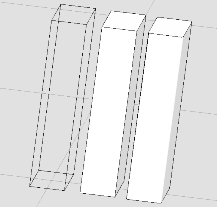<br />**图40 从左至右依次为获取到的线段,原拉伸体,修改后新生成的元素**<br />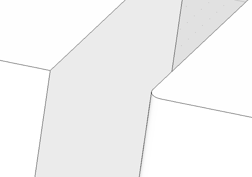<br />**图41 元素对比**
巩固练习(三)参考代码
该练习中的方法涉及到前两期的方法,主要步骤为:
- 使用拉伸实体功能创建梁与圆柱并进行变换
- 对梁截面进行标注并进行变换
- 对梁与圆柱执行布尔运算
对实体进行材质附加 ```csharp
region PracticeWork
public static void CmdPracticeWork(string unparsed) { DgnFile dgnFile = Session.Instance.GetActiveDgnFile();//获得当前激活的文件 DgnModel dgnModel = Session.Instance.GetActiveDgnModel();//获取当前的模型空间 double uorPerMeter = Session.Instance.GetActiveDgnModel().GetModelInfo().UorPerMeter;//分辨率单位转换为米
region Create beam
region Create profile
double H = 700 uorPerMeter/1000; double H1 = 125 uorPerMeter / 1000, H2 = 125 uorPerMeter / 1000; double H3 = 275 uorPerMeter / 1000; double H4 = 75 uorPerMeter / 1000, B4 = 75 uorPerMeter / 1000; double H5 = 100 uorPerMeter / 1000; double B3 = 125 uorPerMeter / 1000; double B1 = 400 uorPerMeter / 1000; double B2 = 300 uorPerMeter / 1000; double B = 150 * uorPerMeter / 1000;
DPoint3d p1 = new DPoint3d(-1 0.5 B1, 0, 0);//声明体元素端点 DPoint3d p2 = new DPoint3d(-1 0.5 B1, 0, H2); DPoint3d p3 = new DPoint3d(-0.5 B, 0, H2 + H5); DPoint3d p4 = new DPoint3d(-0.5 B, 0, H2 + H5 + H3); DPoint3d p5 = new DPoint3d(-0.5 B2, 0, H2 + H5 + H3 + H4); DPoint3d p6 = new DPoint3d(-0.5 B2, 0, H); DPoint3d p7 = new DPoint3d(0.5 B2, 0, H); DPoint3d p8 = new DPoint3d(0.5 B2, 0, H2 + H5 + H3 + H4); DPoint3d p9 = new DPoint3d(0.5 B, 0, H2 + H5 + H3); DPoint3d p10 = new DPoint3d(0.5 B, 0, H2 + H5); DPoint3d p11 = new DPoint3d(0.5 B1, 0, H2); DPoint3d p12 = new DPoint3d(0.5 B1, 0, 0);
DPoint3d[] pos = { p1, p2, p3, p4, p5, p6, p7, p8, p9, p10, p11, p12 };//将面元素端点添加到面元素端点数组中
ShapeElement shape = new ShapeElement(dgnModel, null, pos);//声明形元素
endregion
DPoint3d origin = DPoint3d.Zero;//声明拉伸基点 DVector3d extrudeVector = new DVector3d(0, 12 * uorPerMeter, 0);//声明拉伸向量
SurfaceOrSolidElement beamSolid = SurfaceOrSolidElement.CreateProjectionElement(dgnModel, null, shape, origin, extrudeVector, DTransform3d.Identity, true);//使用投影的方式声明拉伸体元素
endregion
region Create dimension
DPoint3d d1 = new DPoint3d(-0.5 B1, 0, -50 uorPerMeter / 1000);//声明标注点 DPoint3d d2 = new DPoint3d(0.5 B1, 0, -50 uorPerMeter / 1000);//声明标注点 DPoint3d[] dimensionPos1 = { d1, d2 };//声明标注点数组 DMatrix3d dMatrix1 = new DMatrix3d(-1, 0, 0, 0, 0, 1, 0, -1, 0);//声明变换矩阵 DimensionElement dimEle1 = CreateDimensionElement(dgnFile, dgnModel, dimensionPos1, string.Empty, dMatrix1);//声明标注元素 dimEle1.AddToModel();//将标注元素写入模型
DPoint3d d3 = new DPoint3d(-0.5 B1, 0, -10 uorPerMeter / 1000); DPoint3d d4 = new DPoint3d(-0.5 B, 0, -10 uorPerMeter / 1000); DPoint3d d5 = new DPoint3d(0.5 B, 0, -10 uorPerMeter / 1000); DPoint3d d6 = new DPoint3d(0.5 B1, 0, -10 uorPerMeter / 1000); DPoint3d[] dimensionPos2 = { d3, d4, d5, d6 }; DimensionElement dimEle2 = CreateDimensionElement(dgnFile, dgnModel, dimensionPos2, string.Empty, dMatrix1); dimEle2.AddToModel();//将标注元素写入模型
DMatrix3d dMatrix2 = DMatrix3d.FromRows(new DVector3d(0, 1, 0), new DVector3d(-1, 0, 0), new DVector3d(0, 0, 1)); DMatrix3d dMatrix = DMatrix3d.Multiply(dMatrix1, dMatrix2);
DPoint3d d7 = new DPoint3d(-0.5 B1 - 50 uorPerMeter / 1000, 0, 0); DPoint3d d8 = new DPoint3d(-0.5 B1 - 50 uorPerMeter / 1000, 0, H); DPoint3d[] dimensionPos3 = { d7, d8 }; DimensionElement dimEle3 = CreateDimensionElement(dgnFile, dgnModel, dimensionPos3, string.Empty, dMatrix); dimEle3.AddToModel();//将标注元素写入模型
DPoint3d d9 = new DPoint3d(-0.5 B1 - 10 uorPerMeter / 1000, 0, 0); DPoint3d d10 = new DPoint3d(-0.5 B1 - 10 uorPerMeter / 1000, 0, H2); DPoint3d d11 = new DPoint3d(-0.5 B1 - 10 uorPerMeter / 1000, 0, H2 + H5); DPoint3d d12 = new DPoint3d(-0.5 B1 - 10 uorPerMeter / 1000, 0, H2 + H5 + H3); DPoint3d d13 = new DPoint3d(-0.5 B1 - 10 uorPerMeter / 1000, 0, H2 + H5 + H3 + H4); DPoint3d d14 = new DPoint3d(-0.5 B1 - 10 uorPerMeter / 1000, 0, H); DPoint3d[] dimensionPos4 = { d9, d10, d11, d12, d13, d14 }; DimensionElement dimEle4 = CreateDimensionElement(dgnFile, dgnModel, dimensionPos4, string.Empty, dMatrix); dimEle4.AddToModel();//将标注元素写入模型
endregion
region Create column
EllipseElement ellipse = new EllipseElement(dgnModel,null, DPoint3d.Zero,350uorPerMeter/1000, 350 uorPerMeter / 1000,DMatrix3d.Identity);
DVector3d columnVector = new DVector3d(0, 0, 3 * uorPerMeter);//声明拉伸向量
SurfaceOrSolidElement columnSolid = SurfaceOrSolidElement.CreateProjectionElement(dgnModel, null, ellipse, DPoint3d.Zero, columnVector, DTransform3d.Identity, true);//使用投影的方式声明拉伸体元素
DTransform3d dTransform3D= DTransform3d.FromTranslation(new DPoint3d(0,12uorPerMeter,-1uorPerMeter));//声明变换几何,执行元素平移操作 TransformInfo trans = new TransformInfo(dTransform3D);//声明变换信息 columnSolid.ApplyTransform(trans);//对拉伸圆柱体施加变换信息
endregion
region BooleanSubtract
Convert1.ElementToBody(out SolidKernelEntity entity1, beamSolid, true, false, false);//将实体转成SolidKernelEntity Convert1.ElementToBody(out SolidKernelEntity entity2, columnSolid, true, false, false);//将圆台实体元素转成SolidKernelEntity SolidKernelEntity[] entities = { entity2 };//声明实核实体集 Modify.BooleanSubtract(ref entity1, ref entities, entities.Count());//用实核实体集中的实体与实体进行布尔减运算 Convert1.BodyToElement(out Element resultElem, entity1, null, dgnModel);//将结果转换为元素
endregion
region Attach material
MaterialId id = FindMaterial(dgnFile, dgnModel); AttachMaterialToElement(id, resultElem); AttachMaterialToElement(id, columnSolid);
endregion
}
private static void AttachMaterialToElement(MaterialId id, Element elem)
{
if (id != null)
{
MaterialPropertiesExtension propertiesExtension = MaterialPropertiesExtension.GetAsMaterialPropertiesExtension((DisplayableElement)elem);//为拉伸实体元素设置材料属性
propertiesExtension.AddMaterialAttachment(id);//添加嵌入的材料信息
propertiesExtension.StoresAttachmentInfo(id);//保存拉伸实体元素的材料信息
propertiesExtension.AddToModel();//将拉伸实体写入模型
}
}
private static MaterialId FindMaterial(DgnFile dgnFile, DgnModel dgnModel) { MaterialTable matTbl = new MaterialTable(dgnFile);//声明材料表 matTbl.Name = “MyMaterialTable”;//声明材料表名称 PaletteInfo[] palInfo = MaterialManager.GetPalettesInSearchPath(“MS_MATERIAL”);//从MS_MATERIAL的环境变量声明路径下读取材料图表 if (palInfo.Length < 1)//判断是否获取到材料图表 { MessageCenter.Instance.ShowInfoMessage(“Can’t get palette”, null, true);//输出错误信息 return null;//返回 } for (int i = 0; i < palInfo.Count(); i++)//遍历材料图表 { if (palInfo[i].Name == “Concrete&Pavers”)//判断材料图表是否名为Concrete&Pavers { matTbl.AddPalette(palInfo[i]);//添加材料图表至材料表 break;//跳出循环 } else if (i == palInfo.Count() - 1)//若未找到名为lightwidgets的材料图表 { MessageCenter.Instance.ShowErrorMessage(“Can’t find material lib named lightwidgets, please check”, “Can’t find material lib named lightwidgets, please check”, true);//输出错误信息 } } MaterialManager.SetActiveTable(matTbl, dgnModel);//设置当前材料表为激活图表 MaterialManager.SaveTable(matTbl);//保存材料表
MaterialId id = new MaterialId("Concrete_1");//查找名为Concrete_1的材料return id;
}
endregion
/** 参考论坛帖子:* https://communities.bentley.com/communities/other_communities/chinafirst/f/microstation-projectwise/158653/ms-ce-c* https://communities.bentley.com/communities/other_communities/chinafirst/f/microstation-projectwise/200717/thread/601140#601140* https://communities.bentley.com/communities/other_communities/chinafirst/f/microstation-projectwise/221336/abd-ce-c/678991#678991*/private static DimensionElement CreateDimensionElement(DgnFile dgnFile, DgnModel dgnModel, DPoint3d[] pos, string text, DMatrix3d dMatrix){//获取当前dgn文件中名字为"DimStyle"的标注样式,尺寸标注元素的外貌由上百个属性控制,而标注样式是一组预先设置好的属性//获取了预先订制好的标注样式之后,还可以调用DimensionStyle下的各种SetXXX成员函数修改设置的属性DimensionStyle dimStyle = new DimensionStyle("DimStyle", dgnFile);//声明标注样式dimStyle.SetBooleanProp(true, DimStyleProp.Placement_UseStyleAnnotationScale_BOOLINT);//设置标注样式dimStyle.SetDoubleProp(1, DimStyleProp.Placement_AnnotationScale_DOUBLE);dimStyle.SetBooleanProp(true, DimStyleProp.Text_OverrideHeight_BOOLINT);dimStyle.SetDistanceProp(200, DimStyleProp.Text_Height_DISTANCE, dgnModel);dimStyle.SetBooleanProp(true, DimStyleProp.Text_OverrideWidth_BOOLINT);dimStyle.SetDistanceProp(200, DimStyleProp.Text_Width_DISTANCE, dgnModel);dimStyle.SetBooleanProp(true, DimStyleProp.General_UseMinLeader_BOOLINT);dimStyle.SetDoubleProp(0.01, DimStyleProp.Terminator_MinLeader_DOUBLE);dimStyle.SetBooleanProp(true, DimStyleProp.Value_AngleMeasure_BOOLINT);dimStyle.SetAccuracyProp((byte)AnglePrecision.Use1Place, DimStyleProp.Value_AnglePrecision_INTEGER);int alignInt = (int)DimStyleProp_General_Alignment.True;StatusInt status = dimStyle.SetIntegerProp(alignInt, DimStyleProp.General_Alignment_INTEGER);dimStyle.GetIntegerProp(out int valueOut, DimStyleProp.General_Alignment_INTEGER);DgnTextStyle textStyle = new DgnTextStyle("TestStyle", dgnFile);//设置文字样式LevelId lvlId = Settings.GetLevelIdFromName("Default");//设置图层CreateDimensionCallbacks callbacks = new CreateDimensionCallbacks(dimStyle, textStyle, new Symbology(), lvlId, null);//尺寸标注元素的构造函数会调用DimensionCreateData的各个成员函数去获取声明尺寸标注元素需要的各种参数DimensionElement dimEle = new DimensionElement(dgnModel, callbacks, DimensionType.SizeStroke);//声明标注元素if (dimEle.IsValid)//判断标注元素是否有效{for (int i = 0; i < pos.Count(); i++){dimEle.InsertPoint(pos[i], null, dimStyle, -1);//对标注元素设置插入点}dimEle.SetHeight(500);//设置尺寸标注元素的高度dimEle.SetRotationMatrix(dMatrix);//设置变换信息}return dimEle;}
class CreateDimensionCallbacks : DimensionCreateData { private DimensionStyle m_dimStyle; private DgnTextStyle m_textStyle; private Symbology m_symbology; private LevelId m_levelId; private DirectionFormatter m_directionFormatter; public CreateDimensionCallbacks(DimensionStyle dimStyle, DgnTextStyle textStyle, Symbology symb, LevelId levelId, DirectionFormatter formatter) { m_dimStyle = dimStyle; m_textStyle = textStyle; m_symbology = symb; m_levelId = levelId; m_directionFormatter = formatter; }
public override DimensionStyle GetDimensionStyle(){return m_dimStyle;}public override DgnTextStyle GetTextStyle(){return m_textStyle;}public override Symbology GetSymbology(){return m_symbology;}public override LevelId GetLevelId(){return m_levelId;}public override int GetViewNumber(){return 0;}//此函数返回的旋转矩阵与GetViewRotation返回的旋转矩阵共同声明了尺寸标注元素的方向public override DMatrix3d GetDimensionRotation(){return DMatrix3d.Identity;}public override DMatrix3d GetViewRotation(){return DMatrix3d.Identity;}//用于从数字方向值构造字符串。public override DirectionFormatter GetDirectionFormatter(){return m_directionFormatter;}}
```
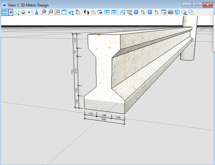
图42 最终效果展示一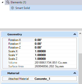
图43 最终效果展示二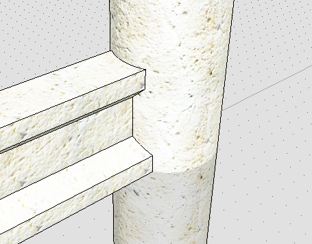
图44 最终效果展示三


