第三期视频回放
第三期代码及课件下载地址
第三期直播内容文字版
MicroStation单位
这里我们着重讨论一下MicroStation二次开发中单位的问题,因为元素是基于屏幕分辨率创建的,而我们需要写入的构件,如果需要与我们当前的单位所匹配,那么就必须在创建构件时,获得实际单位与屏幕分辨率的比值。<br /> 关于修改主单位可以依次点击:File > Settings > File > Design File Settings<br />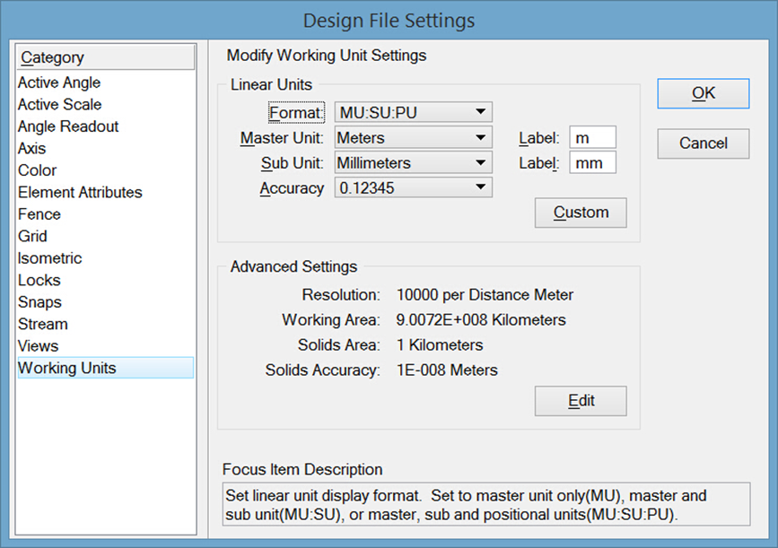<br />**图2 文件设置**<br />**关于设置子单位的初衷:**<br />**设置子单位主要是为了英制单位服务的。我们知道1英尺等于12英寸,对于英制来说,我们可以将主单位设置为英尺,子单位设置为英寸。这样当您想输入2'5"时就可以直接输入2:5而不需要将5"先换算成0.41666666666667'进而换算为2.41666666666667。这种巧妙的设计对于公制来说反而显得多此一举了。**在代码实现中,我们主要获取三种值,分别为用于获取获取主单位与分辨率单位的比值的UorPerMaster,用于获取子单位与分辨率单位的比值的UorPerSub和用于获取米与分辨率单位的比值的UorPerMeter。对于一些需要与主单位相同的情景,我们使用UorPerMaster进行单位的换算,但是,当我们在做一些标准构件时,比如说集水坑,钢筋,管线等,他不会因为当前主单位的不同尺寸有所改变,此时就需要使用UorPerMeter,保证在不同主单位条件下他们的换算关系都是基于分辨率与米之间的。
public static void CmdUnitConversion(string unparsed){double uorPerMas = Session.Instance.GetActiveDgnModel().GetModelInfo().UorPerMaster;//获取主单位与分辨率单位的比值double uorMeter = Session.Instance.GetActiveDgnModel().GetModelInfo().UorPerMeter;//获取米与分辨率单位的比值double uorPerSub = Session.Instance.GetActiveDgnModel().GetModelInfo().UorPerSub;//获取子单位与分辨率单位的比值MessageBox.Show("UorPerMaster = "+ uorPerMas+ "\nUorPerMeter = "+uorMeter+ "\nuorPerSub = "+ uorPerSub);//提示框输出信息}
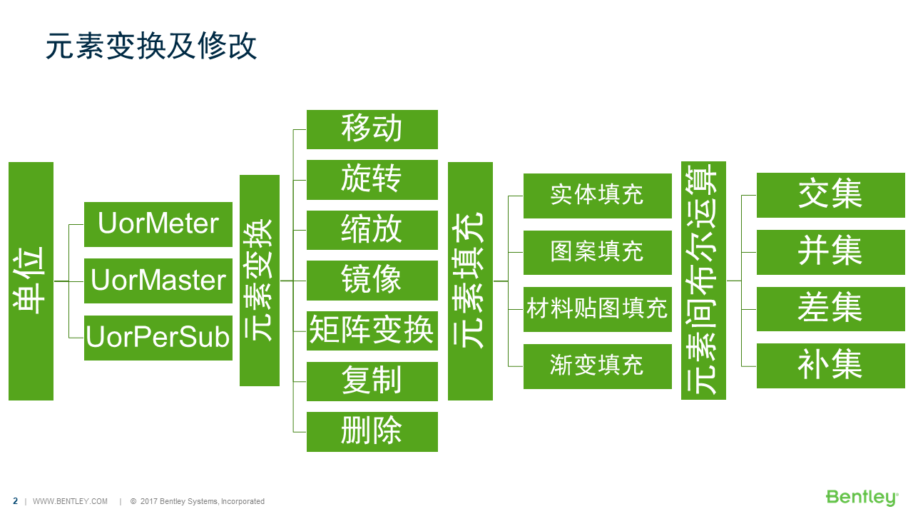
元素变换
变换矩阵(DMatrix3d)
使用变换矩阵对元素进行移动,旋转等操作,它的用法十分灵活,可以使用它进行多维变换。
public static void CmdElementTransformByMatrix(string unparsed){DgnModel dgnModel = Session.Instance.GetActiveDgnModel();//定义当前激活的模型空间double uorPerMas = Session.Instance.GetActiveDgnModel().GetModelInfo().UorPerMaster;//获取主单位与分辨率单位的比值DPoint3d p1 = new DPoint3d(5 * uorPerMas, 5 * uorPerMas, 0);//定义形元素端点DPoint3d p2 = new DPoint3d(10 * uorPerMas, 5 * uorPerMas, 0);DPoint3d p3 = new DPoint3d(10 * uorPerMas, -5 * uorPerMas, 0);DPoint3d p4 = new DPoint3d(5 * uorPerMas, -5 * uorPerMas);DPoint3d[] pos = { p1, p2, p3, p4 };//将端点添加到端点集中ShapeElement shape = new ShapeElement(dgnModel, null, pos);//使用端点集定义形元素DMatrix3d matrix = new DMatrix3d(1, 0, 0, 0, 0, 1, 0, 1, 0);//定义变换矩阵DTransform3d trans = new DTransform3d(matrix);//定义变换几何TransformInfo transform = new TransformInfo(trans);//使用变换几何定义变换信息shape.ApplyTransform(transform);//对形元素应用变换信息shape.AddToModel();//将在内存中定义形元素写入磁盘上文件的模型中}
在本案例中,首先在XY平面内创建了一个边长为10的形元素,然后使用变换矩阵,将Y坐标和Z坐标调换后对形元素应用。生成结果我们可以看到,在XZ平面生成了一个边长为10的形元素,其中原来Y的坐标值变成了Z值。<br />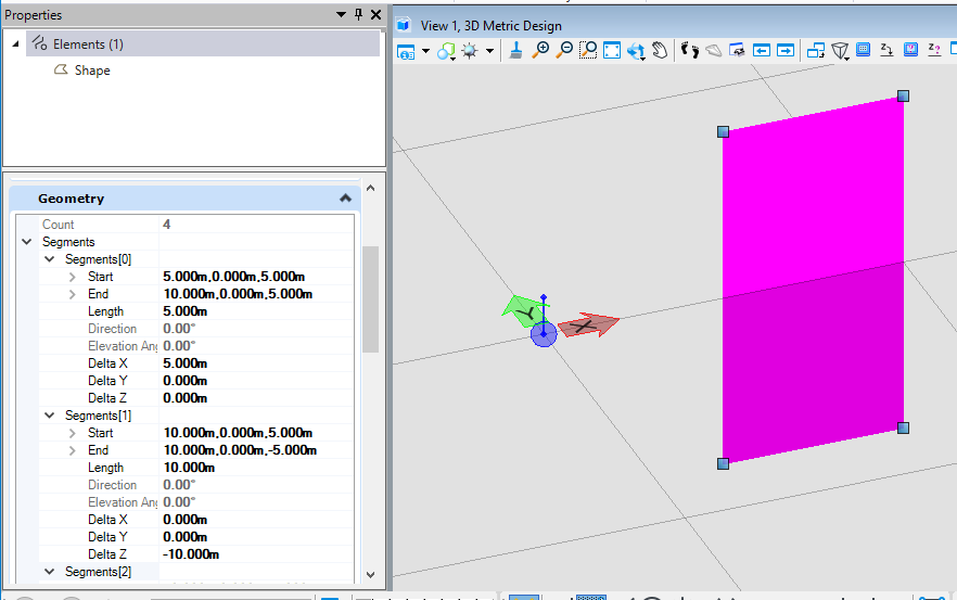<br />**图3 生成结果**
平移(Move)
当我们需要对元素进行平移时,若使用变换矩阵的方式则需要首先对变换矩阵进行计算,十分麻烦,使用DTransform3d.FromTranslation( )可以直接在输入参数中指定平移元素的XYZ坐标值,使用起来更加方便。
public static void CmdElementMove(string unparsed){DgnModel dgnModel = Session.Instance.GetActiveDgnModel();//定义当前激活的模型空间double uorPerMas = Session.Instance.GetActiveDgnModel().GetModelInfo().UorPerMaster;//获取主单位与分辨率单位的比值DPoint3d startPo = DPoint3d.Zero;//定义直线起点DPoint3d endPo = new DPoint3d(10* uorPerMas,0,0);//定义直线终点DSegment3d segment = new DSegment3d(startPo,endPo);//定义几何直线LineElement line = new LineElement(dgnModel,null, segment);//定义线元素DPoint3d transInfo = new DPoint3d(0,5*uorPerMas,0);//定义平移信息 在本文中即向上平移五个单位DTransform3d trans = DTransform3d.FromTranslation(transInfo);//定义变换几何TransformInfo transform = new TransformInfo(trans);//使用变换几何定义变换信息line.ApplyTransform(transform);//对线元素应用变换信息line.AddToModel();//将线元素写入模型}
在本案例中,首先在内存中定义了一个起点在基点,端点在(10,0,0)的直线,然后通过DPoint3d定义XYZ三个方向的平移距离,最后直线进行应用。从结果我们可以看到,最初被定义的直线向Y方向平移了5个单位。<br />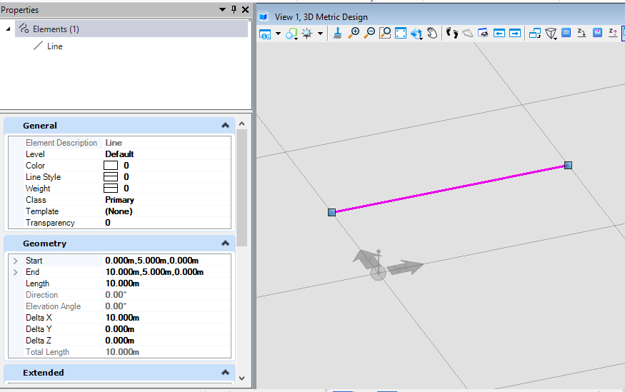<br />**图4 生成结果**
绕基点轴旋转(Rotation)
当我们需要对元素进行旋转时,我们可以直接使用DTransform3d.Rotation( )方法,其中,第一个入参定义旋转轴的向量,第二个参数记录旋转角度。
public static void CmdElementRotateWithDefaultAxis(string unparsed){DgnModel dgnModel = Session.Instance.GetActiveDgnModel();//定义当前激活的模型空间double uorPerMas = Session.Instance.GetActiveDgnModel().GetModelInfo().UorPerMaster;//获取主单位与分辨率单位的比值DPoint3d startPo = new DPoint3d(-10 * uorPerMas, 0, 0);//定义直线起点DPoint3d endPo = new DPoint3d(10 * uorPerMas, 0, 0);//定义直线终点DSegment3d segment = new DSegment3d(startPo, endPo);//定义几何直线LineElement line = new LineElement(dgnModel, null, segment);//定义线元素DVector3d vector = DVector3d.UnitZ;//定义旋转轴向量Angle angle = new Angle();//定义角度angle.Degrees = 45;//设置旋转角度为45度DTransform3d trans = DTransform3d.Rotation(vector, angle);//定义变换几何TransformInfo transform = new TransformInfo(trans);//使用变换几何定义变换信息line.ApplyTransform(transform);//对线元素应用变换信息line.AddToModel();//将线元素写入模型}
在本案例中,首先创建了一个起点在(-10,0,0),终点在(10,0,0)的直线,然后定义相关属性,这里我们设置其旋转轴方向为Z方向,旋转45度。生成的结果即在线元素生成时旋转了45度。<br />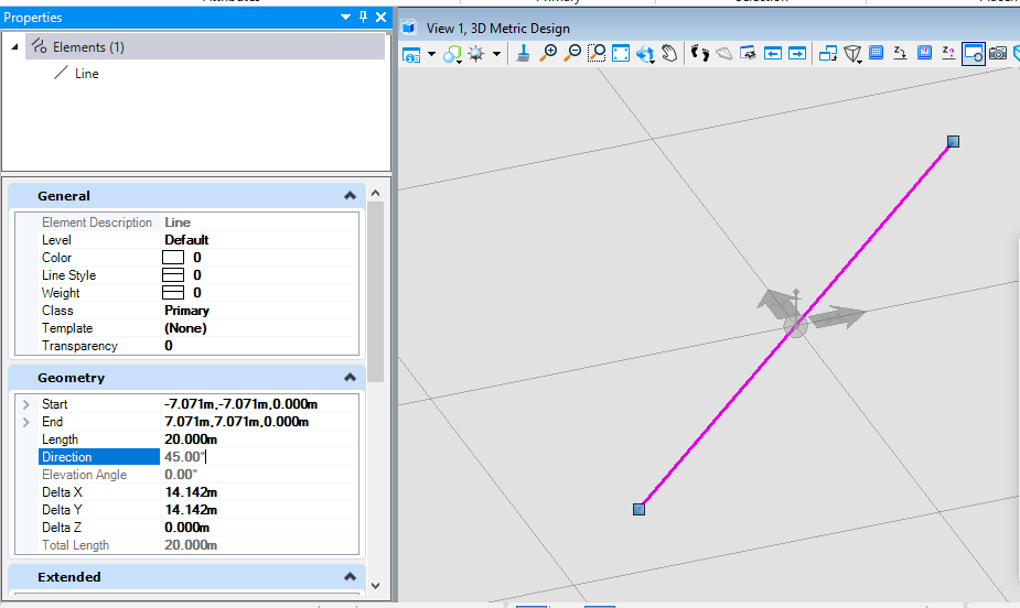<br />**图5 生成结果**
绕自定义轴旋转(Rotation)
当我们需要以指定的基准轴对元素进行旋转时,上方的方法就无法满足要求了,因此我们需要使用DTransform3d.FromRotationAroundLine( ),在这个方法中我们需要首先依次定义旋转基点,旋转轴,旋转角度生成结果。
public static void CmdElementRotateWithCustomAxis(string unparsed){DgnModel dgnModel = Session.Instance.GetActiveDgnModel();//定义当前激活的模型空间double uorPerMas = Session.Instance.GetActiveDgnModel().GetModelInfo().UorPerMaster;//获取主单位与分辨率单位的比值DPoint3d startPo = new DPoint3d(-10 * uorPerMas, 0, 0); ;//定义直线起点DPoint3d endPo = new DPoint3d(10 * uorPerMas, 0, 0);//定义直线终点DSegment3d segment = new DSegment3d(startPo, endPo);//定义几何直线LineElement line = new LineElement(dgnModel, null, segment);//定义线元素DVector3d vector = DVector3d.UnitZ;//定义旋转轴向量Angle angle = new Angle();//定义角度angle.Degrees = 45;//设置旋转角度为45度DTransform3d trans = DTransform3d.FromRotationAroundLine(new DPoint3d(5*uorPerMas,5*uorPerMas,0),vector, angle);//定义变换几何TransformInfo transform = new TransformInfo(trans);//使用变换几何定义变换信息line.ApplyTransform(transform);//对线元素应用变换信息line.AddToModel();//将线元素写入模型}
在本案例中,我首先首先创建了一个起点在(-10,0,0),终点在(10,0,0)的直线,然后定义相关属性,这里我们设置其旋转轴方向为基点坐标,Z方向,旋转45度,生成的结果即在线元素基于设置的基点生成时旋转了45度。下图中我们可以看到,在模型中创建的起点在(-10,0,0),终点在(10,0,0)的直线,绕设置基点(5,5,0)点旋转45度的结果与程序生成的结果一致。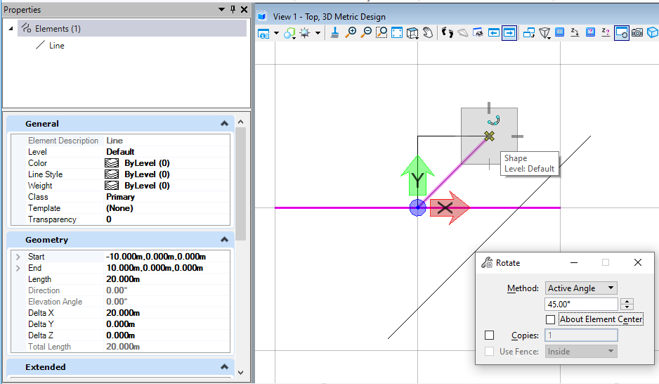
图6 生成结果
整体缩放(Scale)
当我们需要对元素做整体的缩放处理时,就需要使用到DTransform3d.Scale( ),其中的系数指的是缩放的比例。
public static void CmdElementScale1(string unparsed){DgnModel dgnModel = Session.Instance.GetActiveDgnModel();//定义当前激活的模型空间double uorPerMas = Session.Instance.GetActiveDgnModel().GetModelInfo().UorPerMaster;//获取主单位与分辨率单位的比值DPoint3d p1 = new DPoint3d(-5*uorPerMas,5*uorPerMas,0);//定义形元素端点DPoint3d p2 = new DPoint3d(5*uorPerMas,5*uorPerMas,0);DPoint3d p3 = new DPoint3d(5*uorPerMas,-5*uorPerMas,0);DPoint3d p4 = new DPoint3d(-5*uorPerMas,-5*uorPerMas);DPoint3d[] pos = { p1,p2,p3,p4};//将端点添加到端点集中ShapeElement shape = new ShapeElement(dgnModel,null,pos);//使用端点集定义形元素DTransform3d trans = DTransform3d.Scale(2);//定义变换几何TransformInfo transform = new TransformInfo(trans);//使用变换几何定义变换信息shape.ApplyTransform(transform);//对形元素应用变换信息shape.AddToModel();//将形元素写入模型}
在本案例中,首先定义了一个边长为10的形元素,然后我们对这个形元素进行2倍的缩放处理,从结果可以看出,原本边长为10的正方形形元素经过缩放处理后变成了边长为20的形元素。<br />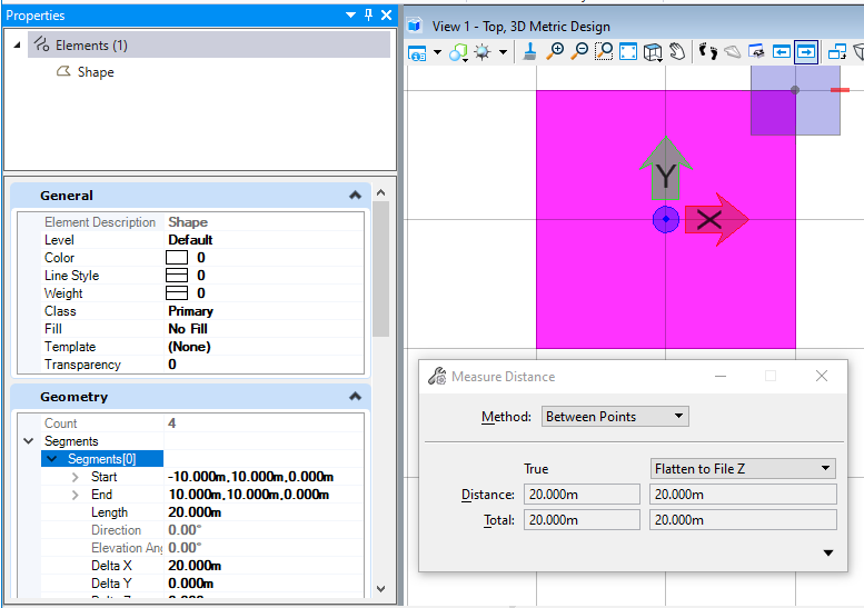<br />**图7 生成结果**
部分缩放(Scale)
当我们需要对指定的轴线方向进行拉伸缩放时,上面的整体缩放就无法满足我们的需求了,此时需要使用DTransform3d.Scale( ),并分别输入X,Y,Z方向的缩放大小,此时元素将按照三个方向分别进行拉伸。
public static void CmdElementScale2(string unparsed){DgnModel dgnModel = Session.Instance.GetActiveDgnModel();//定义当前激活的模型空间double uorPerMas = Session.Instance.GetActiveDgnModel().GetModelInfo().UorPerMaster;//获取主单位与分辨率单位的比值DPoint3d p1 = new DPoint3d(-5 * uorPerMas, 5 * uorPerMas, 0);//定义形元素端点DPoint3d p2 = new DPoint3d(5 * uorPerMas, 5 * uorPerMas, 0);DPoint3d p3 = new DPoint3d(5 * uorPerMas, -5 * uorPerMas, 0);DPoint3d p4 = new DPoint3d(-5 * uorPerMas, -5 * uorPerMas);DPoint3d[] pos = { p1, p2, p3, p4 };//将端点添加到端点集中ShapeElement shape = new ShapeElement(dgnModel, null, pos);//使用端点集定义形元素DTransform3d trans = DTransform3d.Scale(2,1,1);//定义变换几何TransformInfo transform = new TransformInfo(trans);//使用变换几何定义变换信息shape.ApplyTransform(transform);//对形元素应用变换信息shape.AddToModel();//将形元素写入模型}
在本案例中,首先定义了一个边长为10的正方形,然后使用部分缩放对X方向进行缩放,Y方向和Z方向不进行缩放,从结果我们可以看到,X方向被拉伸了2倍,Y方向和Z方向未进行拉伸。<br />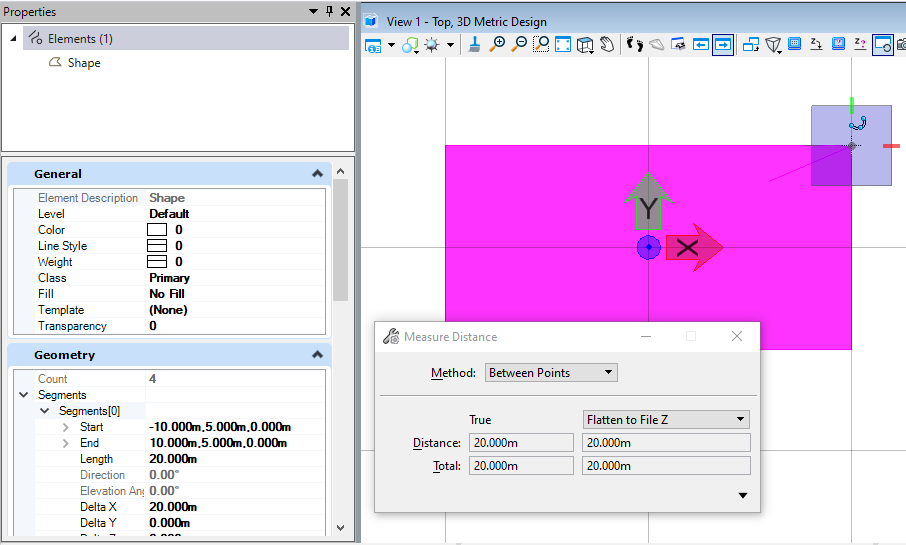<br />**图8 生成结果**
镜像(Mirror)
当我们需要对元素进行镜像时,就需要使用DTransform3d.TryMirrorPointToPoint( ),首先我们需要定义两个镜像点,元素会基于这两个点进行镜像。
public static void CmdElementMirror(string unparsed){DgnModel dgnModel = Session.Instance.GetActiveDgnModel();//定义当前激活的模型空间double uorPerMas = Session.Instance.GetActiveDgnModel().GetModelInfo().UorPerMaster;//获取主单位与分辨率单位的比值DPoint3d p1 = new DPoint3d(5 * uorPerMas, 5 * uorPerMas, 0);//定义形元素端点DPoint3d p2 = new DPoint3d(10 * uorPerMas, 5 * uorPerMas, 0);DPoint3d p3 = new DPoint3d(10 * uorPerMas, -5 * uorPerMas, 0);DPoint3d p4 = new DPoint3d(5 * uorPerMas, -5 * uorPerMas);DPoint3d[] pos = { p1, p2, p3, p4 };//将端点添加到端点集中ShapeElement shape = new ShapeElement(dgnModel, null, pos);//使用端点集定义形元素shape.AddToModel();//将形元素写入模型DPoint3d mirrorPo1 = new DPoint3d(5 * uorPerMas,0,0);//定义镜像点1DPoint3d mirrorPo2 = new DPoint3d(-5 * uorPerMas, 0, 0);//定义镜像点2DTransform3d.TryMirrorPointToPoint(mirrorPo1, mirrorPo2, out DTransform3d mirrorTrans);//根据两镜像点定义变换几何TransformInfo transform = new TransformInfo(mirrorTrans);//使用变换几何定义变换信息shape.ApplyTransform(transform);//对形元素应用变换信息shape.AddToModel();//将形元素写入模型DSegment3d segment = new DSegment3d(mirrorPo1,mirrorPo2);//定义几何直线LineElement line = new LineElement(dgnModel,null, segment);//定义线元素line.AddToModel();//将线元素写入模型}
在本案例中,首先我们在X轴右侧创建了一个长为5,宽为10的矩形形元素,然后通过我们定义的两个镜像点对元素进行镜像操作,右侧生成的形元素即为镜像后生成的结果。<br />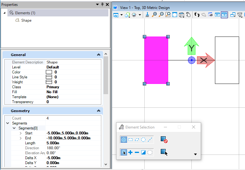<br />**图9 生成结果**
复制(Copy)
当我们需要对元素进行复制时,我们就需要使用到DoCopy( )方法,这种复制的方法不限于在当前模型空间内复制,还可以执行跨模型的复制操作。这里需要注意的是,对ElementCopyContext对象调用Dispose是必要的。ElementCopyContext的Dispose方法执行一些无法在终结器中完成的任务。如果程序未能调用Dispose,则复制的元素可能不完整。
public static void CmdElementCopy(string unparsed){DgnModel dgnModel = Session.Instance.GetActiveDgnModel();//定义当前激活的模型空间double uorPerMas = Session.Instance.GetActiveDgnModel().GetModelInfo().UorPerMaster;//获取主单位与分辨率单位的比值DPoint3d p1 = new DPoint3d(5 * uorPerMas, 5 * uorPerMas, 0);//定义形元素端点DPoint3d p2 = new DPoint3d(10 * uorPerMas, 5 * uorPerMas, 0);DPoint3d p3 = new DPoint3d(10 * uorPerMas, -5 * uorPerMas, 0);DPoint3d p4 = new DPoint3d(5 * uorPerMas, -5 * uorPerMas);DPoint3d[] pos = { p1, p2, p3, p4 };//将端点添加到端点集中ShapeElement shape = new ShapeElement(dgnModel, null, pos);//使用端点集定义形元素shape.AddToModel();//将形元素写入模型using (ElementCopyContext context = new ElementCopyContext(dgnModel))context.DoCopy(shape);/** 在大多数情况下,您不需要设置任何选项。以上代码将图元从一个模型复制到另一个模型,确保复制的图元具有所有属性* 对ElementCopyContext对象调用Dispose是必要的。ElementCopyContext的Dispose方法执行一些无法在终结器中完成的任务。因此,如果程序未能调用Dispose,则复制的元素可能不完整*/}
在本案例中,我们首先创建了一个形元素,然后在当前模型中使用复制方法对形元素进行复制。从结果我们可以看到模型中生成了两个形元素。<br />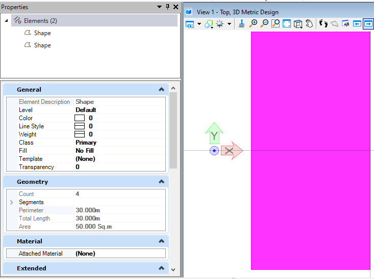<br />**图10 生成结果**
删除(Delete)
当我们对元素进行管理时,肯定会对元素执行删除操作,使用到的方法即为DeleteFromModel( )。
public static void CmdElementDelete(string unparsed)//Case:ElementDeleteExample{DgnModel dgnModel = Session.Instance.GetActiveDgnModel();//定义当前激活的模型空间long id = 1428;//定义需要获取的元素IDElement elem= dgnModel.FindElementById(new ElementId(ref id));//使用ID在模型中寻找所属元素if(elem!=null)//判断元素是否被成功获取{elem.DeleteFromModel();//在模型中删除获取到的元素}}
在本案例中,我们预先在模型中创建了一个形元素,我们在属性界面获得该元素的ID,然后使用元素ID找到对应的元素,使用DeleteFromModel( )删除元素。<br />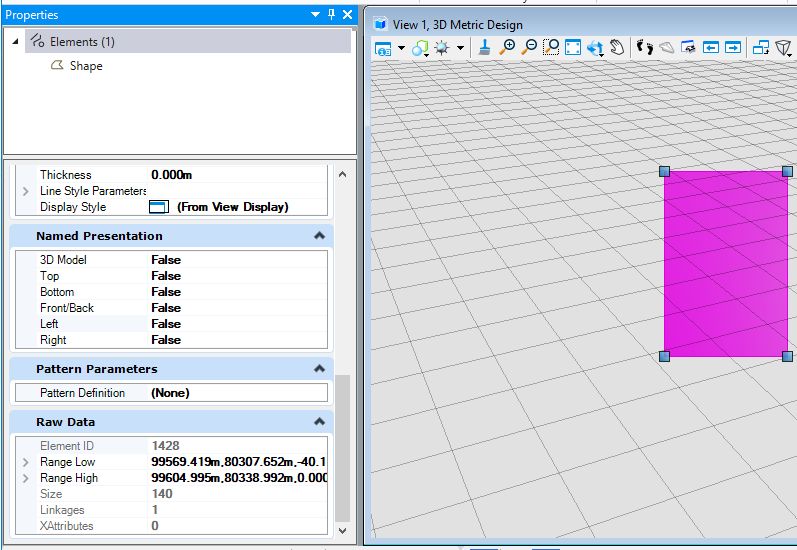<br />**图11 元素属性界面**<br />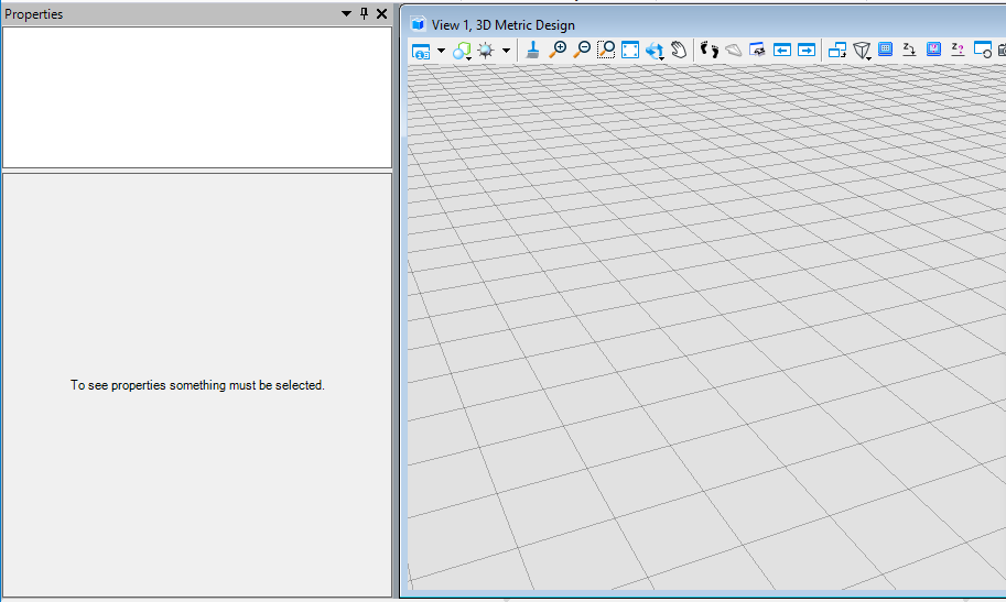<br />**图12 执行结果**
填充
实体填充(SolidFill)
我们可以使用AddSolidFill( )对元素进行实体填充,其中,第一个值为填充颜色索引值,与MicroStation中的颜色索引对应。
public static void CmdElementSolidFill(string unparsed){DgnModel dgnModel = Session.Instance.GetActiveDgnModel();//定义当前激活的模型空间double uorPerMas = Session.Instance.GetActiveDgnModel().GetModelInfo().UorPerMaster;//获取主单位与分辨率单位的比值DPoint3d p1 = new DPoint3d(5 * uorPerMas, 5 * uorPerMas, 0);//定义形元素端点DPoint3d p2 = new DPoint3d(10 * uorPerMas, 5 * uorPerMas, 0);DPoint3d p3 = new DPoint3d(10 * uorPerMas, -5 * uorPerMas, 0);DPoint3d p4 = new DPoint3d(5 * uorPerMas, -5 * uorPerMas);DPoint3d[] pos = { p1, p2, p3, p4 };//将端点添加到端点集中ShapeElement shape = new ShapeElement(dgnModel, null, pos);//使用端点集定义形元素shape.AddSolidFill(3,true);/** 对支持的元素添加实体填充* fillColor:填充颜色,若与边框颜色一致则输入null* alwaysFilled:是否遵守“填充视图”属性*/shape.AddToModel();//将形元素写入模型}
我们可以看到,生成元素的填充已被修改为索引为3(红色)的实体填充。<br />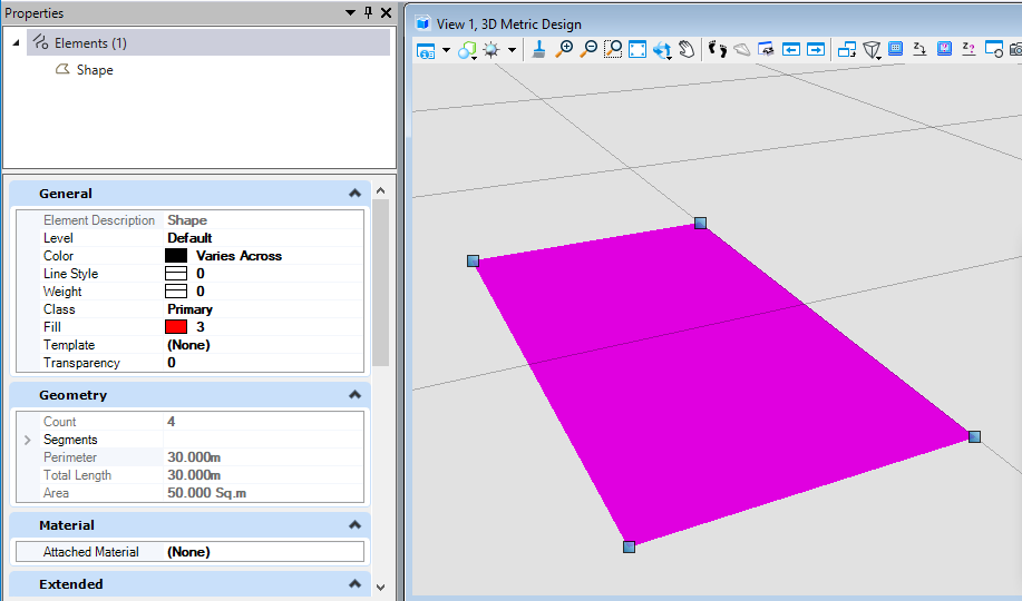<br />**图13 生成元素属性**<br />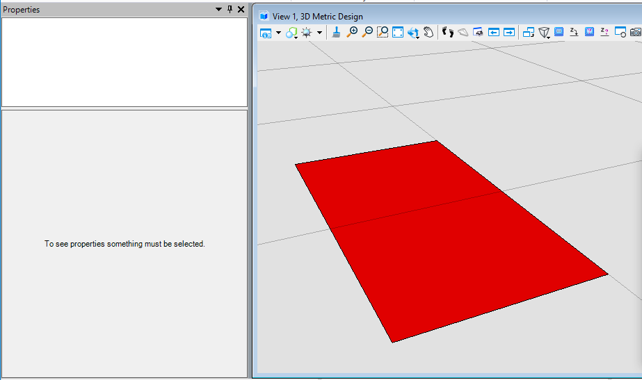<br />**图14 生成结果**
梯度填充(GradientFill)
我们可以使用AddGradientFill( )对元素进行渐变填充,在附加填充之前,需要首先对梯度填充属性进行定义,可定义的属性包括渐变颜色,渐变程度,填充角度,填充色调等。
public static void CmdElementGradientFill(string unparsed){DgnModel dgnModel = Session.Instance.GetActiveDgnModel();//定义当前激活的模型空间double uorPerMas = Session.Instance.GetActiveDgnModel().GetModelInfo().UorPerMaster;//获取主单位与分辨率单位的比值DPoint3d p1 = new DPoint3d(5 * uorPerMas, 5 * uorPerMas, 0);//定义形元素端点DPoint3d p2 = new DPoint3d(10 * uorPerMas, 5 * uorPerMas, 0);DPoint3d p3 = new DPoint3d(10 * uorPerMas, -5 * uorPerMas, 0);DPoint3d p4 = new DPoint3d(5 * uorPerMas, -5 * uorPerMas);DPoint3d[] pos = { p1, p2, p3, p4 };//将端点添加到端点集中ShapeElement shape = new ShapeElement(dgnModel, null, pos);//使用端点集定义形元素GradientSymbology gSymb = new GradientSymbology();//定义梯度填充设置集RgbColorDef[] colors = new RgbColorDef[2];//定义颜色容器double[] values = new double[2];//定义储存填充程度容器colors[0] = new RgbColorDef(255, 0, 0);//设置颜色定义colors[1] = new RgbColorDef(0, 0, 255);values[0] = 0.0;//设置填充程度定义values[1] = 1.0;gSymb.Mode = GradientMode.None;//设置梯度填充模式gSymb.Angle = 10.0;//设置梯度填充角度gSymb.Tint = 2.0;//设置梯度填充色调gSymb.Shift = 3.0;//设置梯度填充转换gSymb.SetKeys(colors, values);//将填充颜色与程度添加到设置集shape.AddGradientFill(gSymb);//对形元素添加渐变填充shape.AddToModel();//将形元素导入模型空间}
我们可以看到,生成元素的填充已被修改为我们所定义的渐变填充。<br />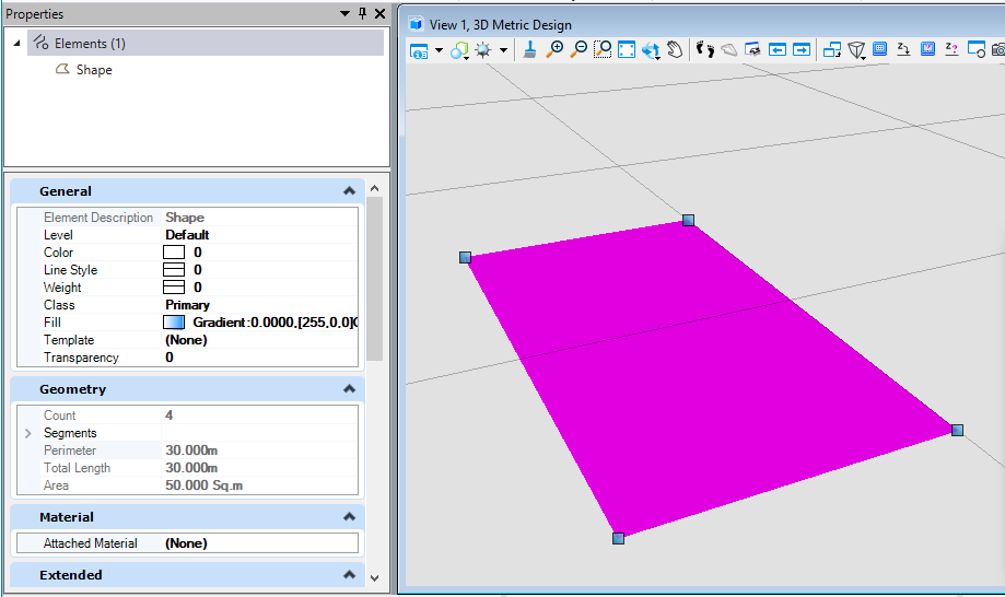<br />**图15 生成元素属性**<br />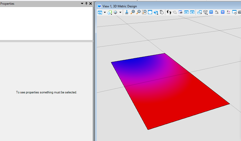<br />**图16 生成结果**
图案填充(PatternFill)
当我们需要使用图案进行填充,或者使用二维进行出图操作时,往往需要使用特定的填充图案指代材质。在这个过程中可能就会涉及到需要与CAD中的图案填充效果保持一致,那么就需要使用图案填充实现。在属性中,我们不仅可以规定填充颜色,间距,还可以通过.pat文件中的信息构建出我们所需要的图案填充。<br /> 关于制作图案填充的更多信息,请参考:[[MSCE]关于图案填充的问题](https://communities.bentley.com/communities/other_communities/chinafirst/f/microstation-projectwise/141119/msce)
public static void CmdElementPatternFill(string unparsed){DgnModel dgnModel = Session.Instance.GetActiveDgnModel();//定义当前激活的模型空间double uorPerMas = Session.Instance.GetActiveDgnModel().GetModelInfo().UorPerMaster;//获取主单位与分辨率单位的比值DPoint3d p1 = new DPoint3d(5 * uorPerMas, 5 * uorPerMas, 0);//定义形元素端点DPoint3d p2 = new DPoint3d(10 * uorPerMas, 5 * uorPerMas, 0);DPoint3d p3 = new DPoint3d(10 * uorPerMas, -5 * uorPerMas, 0);DPoint3d p4 = new DPoint3d(5 * uorPerMas, -5 * uorPerMas);DPoint3d[] pos = { p1, p2, p3, p4 };//将端点添加到端点集中ShapeElement shape = new ShapeElement(dgnModel, null, pos);//使用端点集定义形元素PatternParams param = new PatternParams();//初始化模式定义param.HoleStyle = PatternParamsHoleStyleType.Normal;//设置孔洞样式为普通param.Color = 5;//设置颜色为紫色(索引为5)param.PrimarySpacing = 0.1*uorPerMas;//设置线段间隔距离为0.1mDwgHatchDefLine defLine = new DwgHatchDefLine();//初始化DWG填充定义DwgHatchDefLine[] defLines = { defLine };//将DWG填充定义放入其数组中shape.AddPattern(param, defLines, 0);//对形元素添加图案填充shape.AddToModel();//将形元素导入模型空间}
材质填充(MaterialFill)
当我们需要对元素进行材质填充时,需要首先找到存放该材质的材质表和材质图表,最后将材质挂接到元素上,实现材质填充的最终效果。
public static void CmdElementMaterialFill(string unparsed){DgnFile dgnFile = Session.Instance.GetActiveDgnFile();//定义当前激活的文件信息DgnModel dgnModel = Session.Instance.GetActiveDgnModel();//定义当前激活的模型空间double uorPerMas = Session.Instance.GetActiveDgnModel().GetModelInfo().UorPerMaster;//获取主单位与分辨率单位的比值MaterialTable matTbl = new MaterialTable(dgnFile);//定义材料表matTbl.Name = "MyMaterialTable";//定义材料表名称PaletteInfo[] palInfo = MaterialManager.GetPalettesInSearchPath("MS_MATERIAL");//从MS_MATERIAL的环境变量定义路径下读取材料图表if (palInfo.Length < 1)//判断是否获取到材料图表{MessageCenter.Instance.ShowInfoMessage("Can't get palette", null, true);//输出错误信息return;//返回}for (int i = 0; i < palInfo.Count(); i++)//遍历材料图表{if (palInfo[i].Name == "lightwidgets")//判断材料图表是否名为lightwidgets{matTbl.AddPalette(palInfo[i]);//添加材料图表至材料表break;//跳出循环}else if (i == palInfo.Count() - 1)//若未找到名为lightwidgets的材料图表{MessageCenter.Instance.ShowErrorMessage("Can't find material lib named lightwidgets, please check","Can't find material lib named lightwidgets, please check",true);//输出错误信息}}MaterialManager.SetActiveTable(matTbl, dgnModel);//设置当前材料表为激活图表MaterialManager.SaveTable(matTbl);//保存材料表MaterialId id = new MaterialId("Pavers BC2");//查找名为Pavers BC2的材料DPoint3d[] pos = { DPoint3d.Zero, new DPoint3d(uorPerMas, 0, 0), new DPoint3d(uorPerMas, uorPerMas, 0) };//定义坐标数组ShapeElement shape = new ShapeElement(Session.Instance.GetActiveDgnModel(), null, pos);//定义形元素的实例SurfaceOrSolidElement solid = SolidElement.CreateProjectionElement(dgnModel, null, shape, new DPoint3d(1000, 0, 0),new DVector3d(0, 0, 10*uorPerMas), DTransform3d.Identity, true);//定义拉伸实体元素MaterialPropertiesExtension propertiesExtension = MaterialPropertiesExtension.GetAsMaterialPropertiesExtension(solid);//为拉伸实体元素设置材料属性propertiesExtension.AddMaterialAttachment(id);//添加嵌入的材料信息propertiesExtension.StoresAttachmentInfo(id);//保存拉伸实体元素的材料信息propertiesExtension.AddToModel();//将拉伸实体写入模型}
在本案例中,我们需要挂接名为Pavers BC2的材质,因此我们需要首先找到其所在的材料图表——lightwidgets,然后在图表中根据名称获得。材质图表需要放置在环境变量MS_MATERIAL指定的路径下才可被成功获取。<br />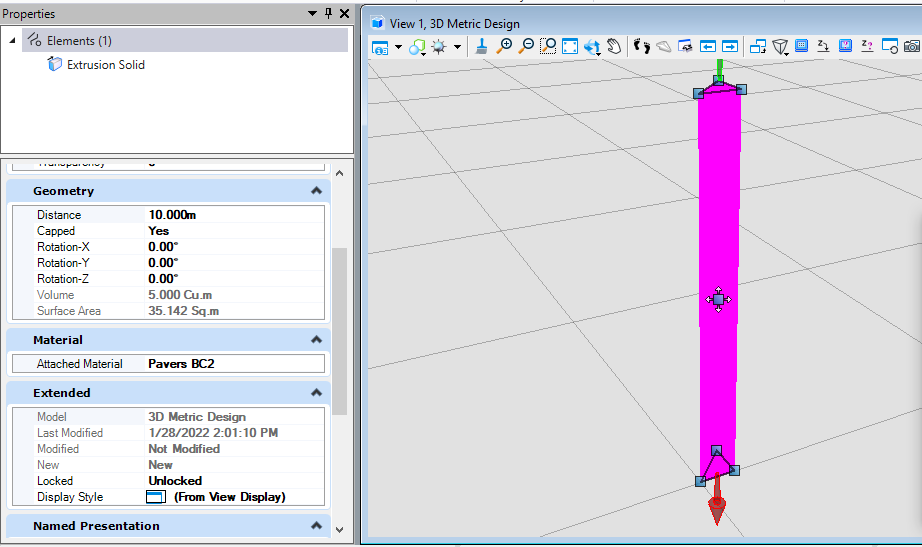<br />**图17 生成元素材料属性**<br />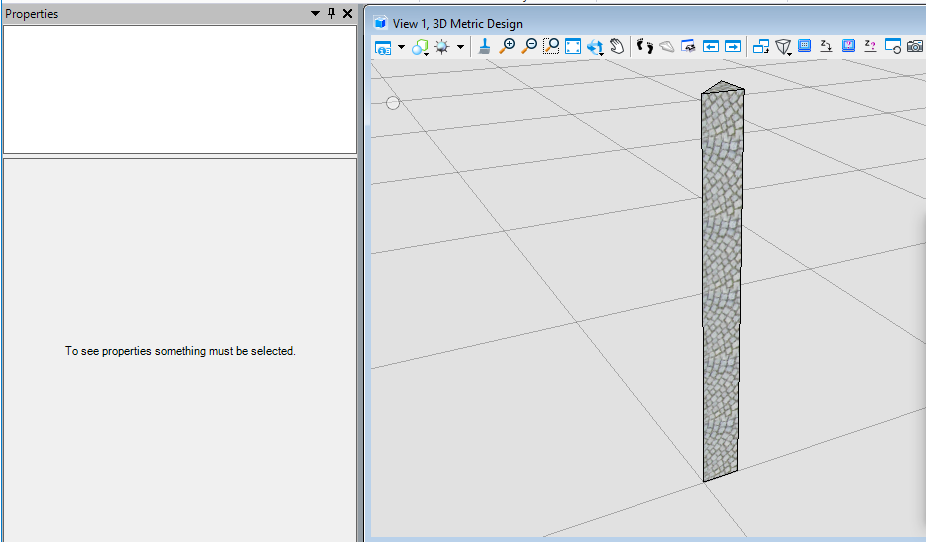<br />**图18 生成结果**
透明度(Transpancy)
当我们需要做出类似透视得效果或者机制时,但是又不想让外部构件直接隐藏,体现内外部构件的相互关系,此时可能会需要将外部构件的透明度提高。
public static void CmdChangeElementTranspancy(string unparsed){DgnModel dgnModel = Session.Instance.GetActiveDgnModel();//定义当前激活的模型空间double uorPerMas = Session.Instance.GetActiveDgnModel().GetModelInfo().UorPerMaster;//获取主单位与分辨率单位的比值DPoint3d p1 = new DPoint3d(5 * uorPerMas, 5 * uorPerMas, 0);//定义形元素端点DPoint3d p2 = new DPoint3d(10 * uorPerMas, 5 * uorPerMas, 0);DPoint3d p3 = new DPoint3d(10 * uorPerMas, -5 * uorPerMas, 0);DPoint3d p4 = new DPoint3d(5 * uorPerMas, -5 * uorPerMas);DPoint3d[] pos = { p1, p2, p3, p4 };//将端点添加到端点集中ShapeElement shape = new ShapeElement(dgnModel, null, pos);//使用端点集定义形元素ElementPropertiesSetter setter = new ElementPropertiesSetter();//用于修改元素属性setter.SetColor((uint)4);//设置元素颜色索引为4setter.SetTransparency(0.5);//设置透明度为50setter.Apply(shape);//将属性修改应用于形元素shape.AddToModel();//将形元素写入模型空间}
在本案例中,首先将形元素的颜色索引值设置为4(黄色),然后对透明度进行调整。需要说明的是,ElementPropertiesSetter不仅不可修改元素颜色,透明度,还可以对字体,图层,线形样式等多种属性进行设置调整。<br />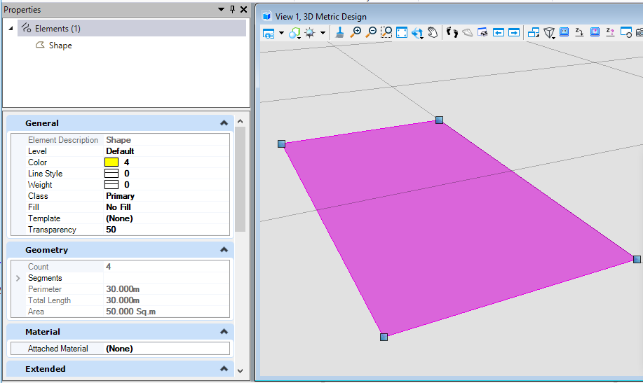<br />**图19 生成元素属性**<br />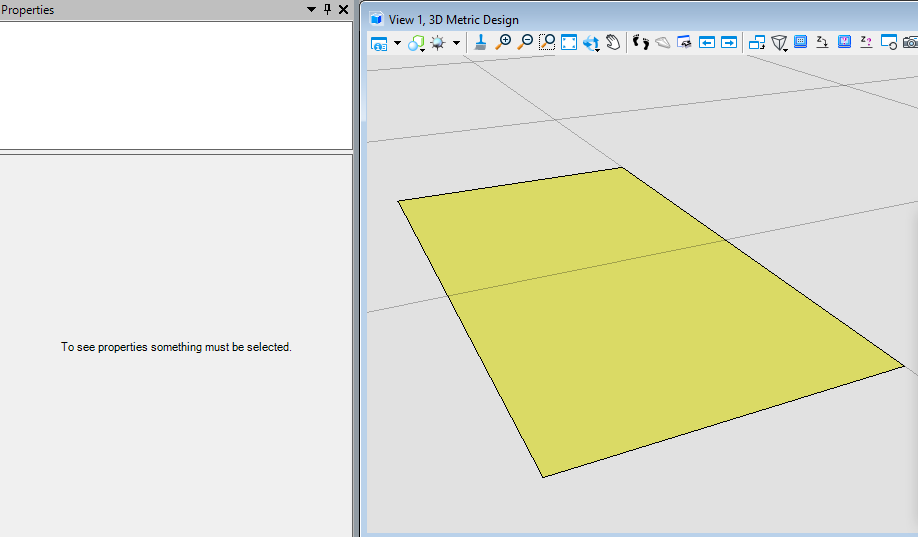<br />**图20 生成结果**
布尔运算
注意:创建的实核实体大小应控制在500m以内,否则可能会生成失败。若需要生成的实核实体范围缺失大于500m,那么可以先将元素缩小进行布尔运算,得到结果再进行元素放大操作即可。
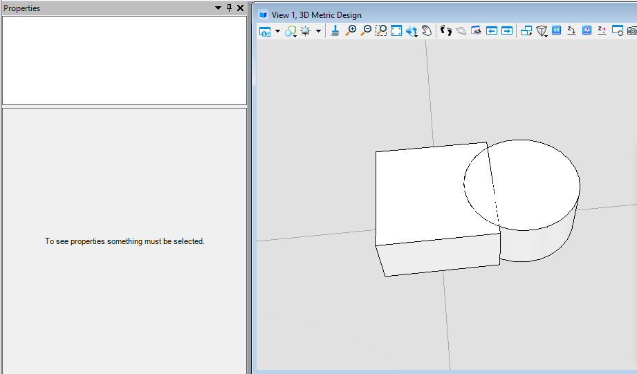
布尔交计算(BooleanIntersect)
该方法用于三维实体,取得实体集中的共有部分生成一个新的智能实体。需要注意的是,创建的实核实体大小应控制在500m以内,否则可能会生成失败。首先我们需要将元素转换为实核实体,然后使用实核实体执行布尔交计算得到最终结果。
public static void CmdBooleanIntersectElement(string unparsed){DgnModel dgnModel = Session.Instance.GetActiveDgnModel();//获取当前的模型空间double uorPerMas = Session.Instance.GetActiveDgnModel().GetModelInfo().UorPerMaster;//获取主单位与分辨率单位的比值#region CreateSolidElement#region Create profileDPoint3d p1 = new DPoint3d(-1* uorPerMas, uorPerMas, 0);//定义形元素端点DPoint3d p2 = new DPoint3d(uorPerMas, uorPerMas, 0);DPoint3d p3 = new DPoint3d(uorPerMas, -uorPerMas, 0);DPoint3d p4 = new DPoint3d(-uorPerMas, -uorPerMas, 0);DPoint3d[] pos = { p1, p2, p3, p4 };//将形元素端点添加到形元素端点数组中ShapeElement shape = new ShapeElement(dgnModel, null, pos);//定义形元素#endregionDPoint3d origin = DPoint3d.Zero;//定义拉伸基点DVector3d extrudeVector = new DVector3d(0, 0, uorPerMas);//定义拉伸向量SurfaceOrSolidElement solid = SurfaceOrSolidElement.CreateProjectionElement(dgnModel, null, shape, origin, extrudeVector, DTransform3d.Identity, true);//定义实体元素solid.AddToModel();//将实体元素写入模型#endregion#region CreateConeElementConeElement cone = new ConeElement(dgnModel,null,uorPerMas,uorPerMas,new DPoint3d(1.5*uorPerMas,0,uorPerMas), new DPoint3d(1.5 * uorPerMas, 0, 0), DMatrix3d.Identity,true);//定义圆台实体cone.AddToModel();//将圆台实体元素写入模型#endregionConvert1.ElementToBody(out SolidKernelEntity entity1,solid,true,false,false);//将实体转成SolidKernelEntityConvert1.ElementToBody(out SolidKernelEntity entity2, cone, true, false, false);//将圆台实体元素转成SolidKernelEntitySolidKernelEntity[] entities = {entity2};//定义实核实体集Modify.BooleanIntersect(ref entity1, ref entities, entities.Count());//用实核实体集中的实体与实体进行布尔交运算Convert1.BodyToElement(out Element resultElem, entity1, null,dgnModel);//将结果转换为元素resultElem.AddToModel();//将元素写入模型空间}
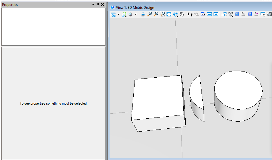
布尔减运算(BooleanSubtract)
该方法用于三维实体,去除被剪切实核实体与用于剪切的实核实体集中共有的部分,生成一个新的智能实体。首先我们需要将元素转换为实核实体,然后使用实核实体执行布尔减计算得到最终结果。
public static void CmdBooleanSubtractElement(string unparsed){DgnModel dgnModel = Session.Instance.GetActiveDgnModel();//获取当前的模型空间double uorPerMas = Session.Instance.GetActiveDgnModel().GetModelInfo().UorPerMaster;//获取主单位与分辨率单位的比值#region CreateSolidElement#region Create profileDPoint3d p1 = new DPoint3d(-1 * uorPerMas, uorPerMas, 0);//定义体元素端点DPoint3d p2 = new DPoint3d(uorPerMas, uorPerMas, 0);DPoint3d p3 = new DPoint3d(uorPerMas, -uorPerMas, 0);DPoint3d p4 = new DPoint3d(-uorPerMas, -uorPerMas, 0);DPoint3d[] pos = { p1, p2, p3, p4 };//将面元素端点添加到面元素端点数组中ShapeElement shape = new ShapeElement(dgnModel, null, pos);//定义形元素#endregionDPoint3d origin = DPoint3d.Zero;//定义拉伸基点DVector3d extrudeVector = new DVector3d(0, 0, uorPerMas);//定义拉伸向量SurfaceOrSolidElement solid = SurfaceOrSolidElement.CreateProjectionElement(dgnModel, null, shape, origin, extrudeVector, DTransform3d.Identity, true);//定义实体元素solid.AddToModel();//将实体元素写入模型#endregion#region CreateConeElementConeElement cone = new ConeElement(dgnModel, null, uorPerMas, uorPerMas, new DPoint3d(1.5 * uorPerMas, 0, uorPerMas), new DPoint3d(1.5 * uorPerMas, 0, 0), DMatrix3d.Identity, true);//定义圆台实体cone.AddToModel();//将圆台实体元素写入模型#endregionConvert1.ElementToBody(out SolidKernelEntity entity1, solid, true, false, false);//将实体转成SolidKernelEntityConvert1.ElementToBody(out SolidKernelEntity entity2, cone, true, false, false);//将圆台实体元素转成SolidKernelEntitySolidKernelEntity[] entities = { entity2 };//定义实核实体集Modify.BooleanSubtract(ref entity1, ref entities, entities.Count());//用实核实体集中的实体与实体进行布尔减运算Convert1.BodyToElement(out Element resultElem, entity1, null, dgnModel);//将结果转换为元素resultElem.AddToModel();//将元素写入模型空间}
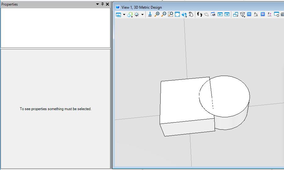
布尔并运算(BooleanUnion)
该方法用于三维实体,取得实体集中的并集部分生成一个新的智能实体。首先我们需要将元素转换为实核实体,然后使用实核实体执行布尔并计算得到最终结果。
public static void CmdBooleanUnionElement(string unparsed){DgnModel dgnModel = Session.Instance.GetActiveDgnModel();//获取当前的模型空间double uorPerMas = Session.Instance.GetActiveDgnModel().GetModelInfo().UorPerMaster;//获取主单位与分辨率单位的比值#region CreateSolidElement#region Create profileDPoint3d p1 = new DPoint3d(-1 * uorPerMas, uorPerMas, 0);//定义体元素端点DPoint3d p2 = new DPoint3d(uorPerMas, uorPerMas, 0);DPoint3d p3 = new DPoint3d(uorPerMas, -uorPerMas, 0);DPoint3d p4 = new DPoint3d(-uorPerMas, -uorPerMas, 0);DPoint3d[] pos = { p1, p2, p3, p4 };//将面元素端点添加到面元素端点数组中ShapeElement shape = new ShapeElement(dgnModel, null, pos);//定义形元素#endregionDPoint3d origin = DPoint3d.Zero;//定义拉伸基点DVector3d extrudeVector = new DVector3d(0, 0, uorPerMas);//定义拉伸向量SurfaceOrSolidElement solid = SurfaceOrSolidElement.CreateProjectionElement(dgnModel, null, shape, origin, extrudeVector, DTransform3d.Identity, true);//定义实体元素solid.AddToModel();//将实体元素写入模型#endregion#region CreateConeElementConeElement cone = new ConeElement(dgnModel, null, uorPerMas, uorPerMas, new DPoint3d(1.5 * uorPerMas, 0, uorPerMas), new DPoint3d(1.5 * uorPerMas, 0, 0), DMatrix3d.Identity, true);//定义圆台实体cone.AddToModel();//将圆台实体元素写入模型#endregionConvert1.ElementToBody(out SolidKernelEntity entity1, solid, true, false, false);//将实体转成SolidKernelEntityConvert1.ElementToBody(out SolidKernelEntity entity2, cone, true, false, false);//将圆台实体元素转成SolidKernelEntitySolidKernelEntity[] entities = { entity2 };//定义实核实体集Modify.BooleanUnion(ref entity1, ref entities, entities.Count());//用实核实体集中的实体与实体进行布尔并运算Convert1.BodyToElement(out Element resultElem, entity1, null, dgnModel);//将结果转换为元素resultElem.AddToModel();//将元素写入模型空间}
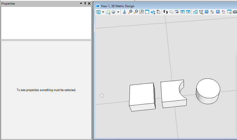
布尔切割运算(BooleanCut)
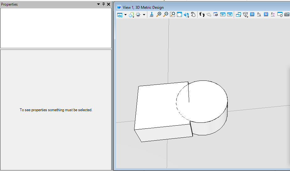
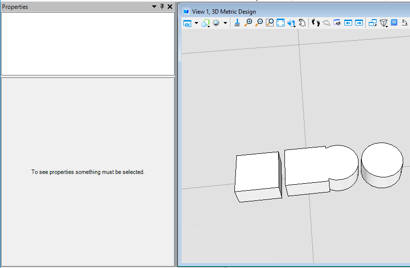
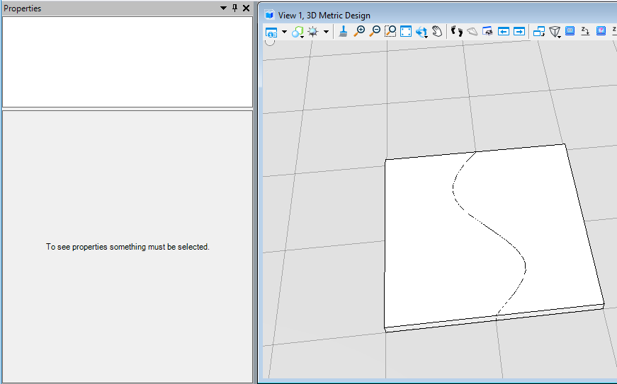
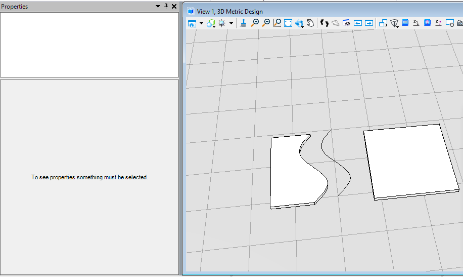
该方法用于一条曲线以某个方向对实核实体进行切割的操作。首先我们需要将被切割的元素转化为实核实体,然后使用曲线对实核实体进行切割生成切割后的结果。在本案例中,首先创建了一条用于切割的B样条曲线,然后使用B样条曲线定义CurveVector,在使用方向向量定义切割方向后对转换为实核实体后的元素切割,最终生成切割后的智能实体。
public static void CmdBooleanCutElement(string unparsed){DgnModel dgnModel = Session.Instance.GetActiveDgnModel();//获取当前的模型空间double uorPerMas = Session.Instance.GetActiveDgnModel().GetModelInfo().UorPerMaster;//获取主单位与分辨率单位的比值#region CreateSolidElement#region Create profileDPoint3d p1 = new DPoint3d(-10 * uorPerMas, 10*uorPerMas, 0);//定义体元素端点DPoint3d p2 = new DPoint3d(10 * uorPerMas, 10*uorPerMas, 0);DPoint3d p3 = new DPoint3d(10 * uorPerMas, -10 * uorPerMas, 0);DPoint3d p4 = new DPoint3d(-10 * uorPerMas, -10 * uorPerMas, 0);DPoint3d[] pos = { p1, p2, p3, p4 };//将面元素端点添加到面元素端点数组中ShapeElement shape = new ShapeElement(dgnModel, null, pos);//定义形元素#endregionDPoint3d origin = DPoint3d.Zero;//定义拉伸基点DVector3d extrudeVector = new DVector3d(0, 0, uorPerMas);//定义拉伸向量SurfaceOrSolidElement solid = SurfaceOrSolidElement.CreateProjectionElement(dgnModel, null, shape, origin, extrudeVector, DTransform3d.Identity, true);//定义实体元素solid.AddToModel();//将实体元素写入模型#endregionConvert1.ElementToBody(out SolidKernelEntity entity, solid, true, false, false);//将实体转成SolidKernelEntity#region CreateBSplineCurveElementDPoint3d[] poles = new DPoint3d[6];//定义B样条曲线的节点poles[0] = new DPoint3d(0, 10*uorPerMas, 0);//定义节点坐标poles[1] = new DPoint3d(-5*uorPerMas, 5*uorPerMas, 0);poles[2] = new DPoint3d(0,0,0);poles[3] = new DPoint3d(5*uorPerMas,-5*uorPerMas,0);poles[4] = new DPoint3d(2*uorPerMas, -8 * uorPerMas, 0);poles[5] = new DPoint3d(0, -10 * uorPerMas, 0);MSBsplineCurve curve = MSBsplineCurve.CreateFromPoles(poles, null, null, 4, false, false);//定义B样条曲线BSplineCurveElement bSplineCurve = new BSplineCurveElement(dgnModel,null, curve);//定义B样条曲线元素bSplineCurve.AddToModel();//将B样条曲线元素写入模型#endregionDVector3d vector = DVector3d.UnitZ;//定义切割法线Modify.BooleanCut(ref entity, bSplineCurve.GetCurveVector(),Modify.CutDirectionMode.Both,Modify.CutDepthMode.All, 0, false, vector, 0);//用实核实体集中的实体与实体进行布尔切割运算Convert1.BodyToElement(out Element resultElem, entity, null, dgnModel);//将结果转换为元素resultElem.AddToModel();//将元素写入模型空间}
巩固练习(二)参考代码
实现思路:首先创建形元素和拉伸向量后创建拉伸实体,然后再根据放置的位置创建文字元素和标注元素。
public static void CmdPracticeWork(string unparsed){DgnFile dgnFile = Session.Instance.GetActiveDgnFile();//定义当前激活的文件DgnModel dgnModel = Session.Instance.GetActiveDgnModel();//获取当前的模型空间#region Create profileint H = 700 * 10000;int H1 =125 * 10000, H2 = 125 * 10000;int H3 = 275 * 10000;int H4 = 75 * 10000, B4 = 75 * 10000;int H5 = 100 * 10000;int B3 = 125 * 10000;int B1 = 400 * 10000;int B2 = 300 * 10000;int B = 150 * 10000;DPoint3d p1 = new DPoint3d(-1*0.5*B1, 0, 0);//定义体元素端点DPoint3d p2 = new DPoint3d(-1*0.5*B1,H2,0);DPoint3d p3 = new DPoint3d(-0.5*B,H2+H5,0);DPoint3d p4 = new DPoint3d(-0.5*B,H2+H5+H3,0);DPoint3d p5 = new DPoint3d(-0.5*B2,H2+H5+H3+H4, 0);DPoint3d p6 = new DPoint3d(-0.5*B2,H, 0);DPoint3d p7 = new DPoint3d(0.5*B2,H,0);DPoint3d p8 = new DPoint3d(0.5*B2, H2 + H5 + H3 + H4,0);DPoint3d p9 = new DPoint3d(0.5 * B, H2 + H5 + H3,0);DPoint3d p10 = new DPoint3d(0.5 * B,H2 + H5, 0);DPoint3d p11 = new DPoint3d(0.5 * B1, H2,0);DPoint3d p12 = new DPoint3d(0.5 * B1, 0, 0);DPoint3d[] pos = { p1, p2, p3, p4,p5,p6,p7,p8,p9,p10,p11,p12 };//将面元素端点添加到面元素端点数组中ShapeElement shape = new ShapeElement(dgnModel, null, pos);//定义形元素#endregionDPoint3d origin = DPoint3d.Zero;//定义拉伸基点DVector3d extrudeVector = new DVector3d(0, 0,-12000*10000);//定义拉伸向量SurfaceOrSolidElement solid = SurfaceOrSolidElement.CreateProjectionElement(dgnModel, null, shape, origin, extrudeVector, DTransform3d.Identity, true);//使用投影的方式定义拉伸体元素solid.AddToModel();//将拉伸体写入模型DPoint3d d1 = new DPoint3d(-0.5*B2, H + 50*10000,0);DPoint3d d2 = new DPoint3d(0.5*B2, H+ 50 * 10000,0);DPoint3d[] dimensionPos1 = { d1, d2 };DimensionElement dimEle1 = CreateDimensionElement(dgnFile,dgnModel , dimensionPos1);dimEle1.AddToModel();DPoint3d d3 = new DPoint3d(-0.5*B2, H + 10 * 10000,0);DPoint3d d4 = new DPoint3d(-0.5*B, H+ 10 * 10000,0);DPoint3d d5 = new DPoint3d(0.5*B, H + 10 *10000, 0);DPoint3d d6 = new DPoint3d(0.5*B2,H + 10 *10000, 0);DPoint3d[] dimensionPos2 = { d3, d4,d5,d6 };DimensionElement dimEle2 = CreateDimensionElement(dgnFile, dgnModel, dimensionPos2);dimEle2.AddToModel();TextBlockProperties txtBlockProp = new TextBlockProperties(dgnModel);//定义文本属性txtBlockProp.IsViewIndependent = false;//设置文本非独立于视图ParagraphProperties paraProp = new ParagraphProperties(dgnModel);//定义段落属性DgnTextStyle txtStyle = DgnTextStyle.GetSettings(dgnFile);//从激活的文件中定义文字样式RunProperties runProp = new RunProperties(txtStyle, dgnModel);//定义运行属性TextBlock txtBlock = new TextBlock(txtBlockProp, paraProp, runProp, dgnModel);//定义文本块txtBlock.AppendText("Side View");//设置文本块文字内容DPoint3d txtOrigin = new DPoint3d(0,-2*10000,0);txtBlock.SetUserOrigin(txtOrigin);//设置文本块放置位置TextElement text = (TextElement)TextElement.CreateElement(null, txtBlock);//定义文本元素DTransform3d trans = DTransform3d.Scale(40);TransformInfo transInfo = new TransformInfo(trans);text.ApplyTransform(transInfo);text.AddToModel();//将生成的文本元素写入模型}private static DimensionElement CreateDimensionElement(DgnFile dgnFile, DgnModel dgnModel, DPoint3d[]pos){//获取当前dgn文件中名字为"DimStyle"的标注样式,尺寸标注元素的外貌由上百个属性控制,而标注样式是一组预先设置好的属性//获取了预先订制好的标注样式之后,还可以调用DimensionStyle下的各种SetXXX成员函数修改设置的属性DimensionStyle dimStyle = new DimensionStyle("DimStyle", dgnFile);//定义标注样式dimStyle.SetBooleanProp(true, DimStyleProp.Placement_UseStyleAnnotationScale_BOOLINT);//设置标注样式dimStyle.SetDoubleProp(1, DimStyleProp.Placement_AnnotationScale_DOUBLE);dimStyle.SetBooleanProp(true, DimStyleProp.Text_OverrideHeight_BOOLINT);dimStyle.SetDistanceProp(20 * 10000, DimStyleProp.Text_Height_DISTANCE, dgnModel);dimStyle.SetBooleanProp(true, DimStyleProp.Text_OverrideWidth_BOOLINT);dimStyle.SetDistanceProp(20 * 10000, DimStyleProp.Text_Width_DISTANCE, dgnModel);dimStyle.SetBooleanProp(true, DimStyleProp.General_UseMinLeader_BOOLINT);dimStyle.SetDoubleProp(0.01, DimStyleProp.Terminator_MinLeader_DOUBLE);dimStyle.SetBooleanProp(true, DimStyleProp.Value_AngleMeasure_BOOLINT);dimStyle.SetAccuracyProp((byte)AnglePrecision.Use1Place, DimStyleProp.Value_AnglePrecision_INTEGER);int alignInt = (int)DimStyleProp_General_Alignment.True;StatusInt status = dimStyle.SetIntegerProp(alignInt, DimStyleProp.General_Alignment_INTEGER);dimStyle.GetIntegerProp(out int valueOut, DimStyleProp.General_Alignment_INTEGER);DgnTextStyle textStyle = new DgnTextStyle("TestStyle", dgnFile);//设置文字样式LevelId lvlId = Settings.GetLevelIdFromName("Default");//设置图层CreateDimensionCallbacks callbacks = new CreateDimensionCallbacks(dimStyle, textStyle, new Symbology(), lvlId, null);//尺寸标注元素的构造函数会调用DimensionCreateData的各个成员函数去获取定义尺寸标注元素需要的各种参数DimensionElement dimEle = new DimensionElement(dgnModel, callbacks, DimensionType.SizeStroke);//定义标注元素if (dimEle.IsValid)//判断标注元素是否有效{for(int i=0;i<pos.Count();i++){dimEle.InsertPoint(pos[i], null, dimStyle, -1);//对标注元素设置插入点}dimEle.SetHeight(50*10000);//设置尺寸标注元素的高度dimEle.SetRotationMatrix(DMatrix3d.Identity);//设置变换信息}return dimEle;}class CreateDimensionCallbacks : DimensionCreateData{private DimensionStyle m_dimStyle;private DgnTextStyle m_textStyle;private Symbology m_symbology;private LevelId m_levelId;private DirectionFormatter m_directionFormatter;public CreateDimensionCallbacks(DimensionStyle dimStyle, DgnTextStyle textStyle, Symbology symb, LevelId levelId, DirectionFormatter formatter){m_dimStyle = dimStyle;m_textStyle = textStyle;m_symbology = symb;m_levelId = levelId;m_directionFormatter = formatter;}public override DimensionStyle GetDimensionStyle(){return m_dimStyle;}public override DgnTextStyle GetTextStyle(){return m_textStyle;}public override Symbology GetSymbology(){return m_symbology;}public override LevelId GetLevelId(){return m_levelId;}public override int GetViewNumber(){return 0;}//此函数返回的旋转矩阵与GetViewRotation返回的旋转矩阵共同定义了尺寸标注元素的方向public override DMatrix3d GetDimensionRotation(){return DMatrix3d.Identity;}public override DMatrix3d GetViewRotation(){return DMatrix3d.Identity;}//用于从数字方向值构造字符串。public override DirectionFormatter GetDirectionFormatter(){return m_directionFormatter;}}
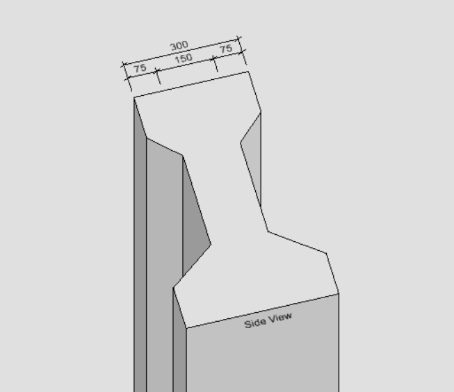
图29 生成结果展示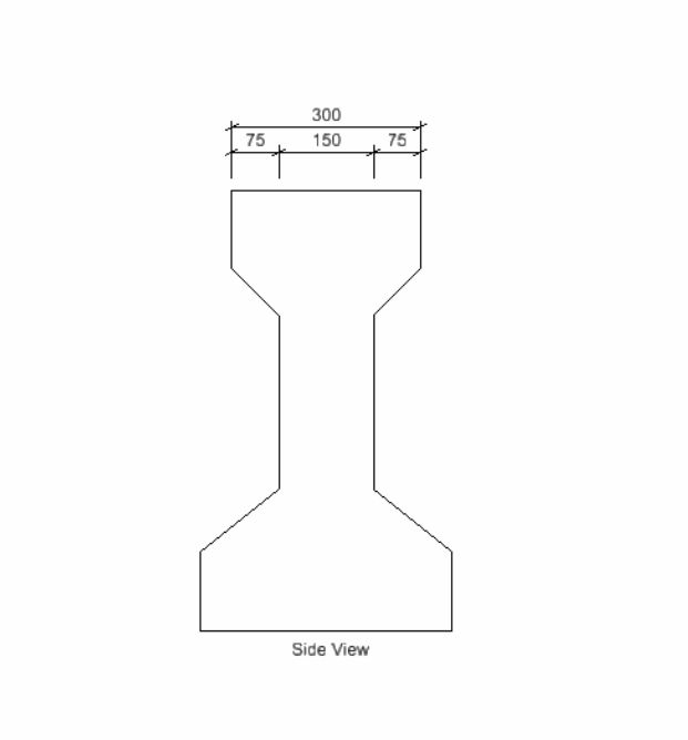
图30 生成结果展示

若有收获,就点个赞吧
0 人点赞
