1.采用模拟电路方式测量IGBT模块NTC温度传感器温度:
这个基本的方法是基于一个分压器作为热敏装置,如下图所示: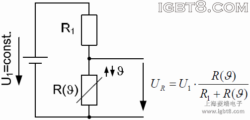
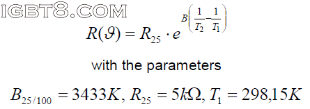
NTC的特性在数据手册中有两种不同的格式,一种图形方式R=f(θ),该函数可近似解析描述该图形的全部参数。有效的数学表达式如下:为了更精确地计算,如果集中在一个较小的温度范围,规格书也提供了B25/50及B25/80的值。文章来源:http://www.igbt8.com/sr/162.html
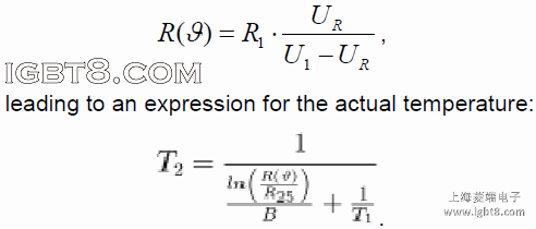
根据已知测量的UR,实际电阻R(θ)的值可由下式计算:如果有一个温度期待值,该方程可以很容易地通过微处理器处理,采用数字化的UR作为输入。
如果只是需要一个最高温度作为阈值信号,采用一个比较器触发预定值就足够了。
分压器电阻R1的规定:
Choosing R1 needs to be done carefully to achieve a proper reading. If chosen too small, the flowing current inside the NTC will lead to losses that in turn heat up the device thereby falsifying the measured results. If, on the other hand, R1 is chosen too large, the measured voltage gets too small and in turn the measurement looses accuracy again.
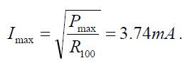
To minimize the influence of the current, a thermal view is helpful. The thermal conductivity for the NTC is 145K/W. If a 1K influence is tolerable, the power dissipation inside the NTC may not exceed Pmax=6.9mW.
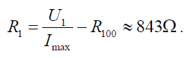
Assuming that a measurement up to 100°C needs to be done, the NTC will reach a value of R100=493. From this, the maximum current can be calculated to beWith a supply voltage U1=5V and a current limit of 3mA, the resistor R1 becomesAs there is no such resistor, 910can be chosen, leading to Imax=3.56mA; any value that limits the current to I<4mA can be considered as long as 1K difference is tolerable.
2.采用数字方式测量IGBT模块NTC温度传感器温度:
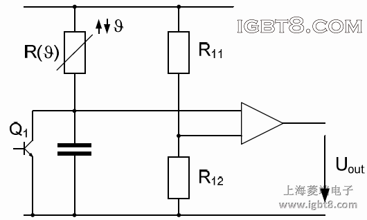
除了用一个电压分压器,NTC电阻随温度的变化可用来影响一个RC网络的时间常数,如下图所示:Figure 7 Basic schematic to get a digital temperature information
电阻R11、R12决定了比较器改变输出状态的阈值,输出信号电压Uout被用来触发晶体管Q1以使电容器放电。电容通过NTC电阻R(θ)充电,Uout以一定的频率fout=g(θ)工作在脉冲模式。
为了根据Uout重建实际温度,采用一个规定的时间段内的脉冲计数是足够的。脉冲数代表了温度值,脉冲数与温度的映射可以通过解析描述或者两个最接近的值之间的插值查表。

若有收获,就点个赞吧
0 人点赞
