1 实验名称
2 实验目的和要求
目的:
理解VLAN如何跨交换机实现。
实现功能:
使在同一VLAN里的计算机系统能跨交换机进行相互通信,而在不同VLAN里的计算机系统不能进行相互通信。
3 实验原理
Tag Vlan是基于交换机端口的另外一种类型,主要用于实现跨交换机的相同VLAN内可以直接访问,同时对于不同VLAN的主机进行隔离。Tag Vlan遵循IEEE802.1q协议标准。在利用配置了Tag Vlan的接口进行数据传输是,需要在数据帧内添加4个字节的802.1q标签信息,用于标识该数据帧属于哪个VLAN,以便于对端交换机接收到数据帧后进行准确的过虑。
4 实验步骤和结果
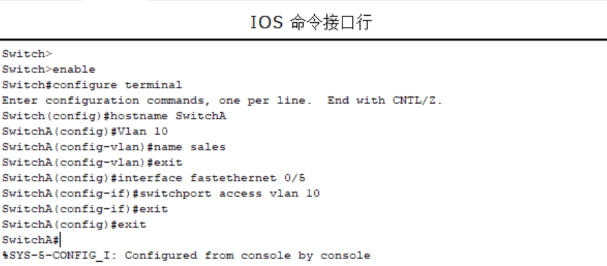
第一步:在第一台交换机上把交换机命名为SwitchA并创建Vlan 10,并将0/5端口划分到Vlan 10中。
Switch>Switch>enableSwitch#configure terminalEnter configuration commands, one per line. End with CNTL/Z.Switch(config)#hostname SwitchASwitchA(config)#Vlan 10SwitchA(config-vlan)#name salesSwitchA(config-vlan)#exitSwitchA(config)#interface fastethernet 0/5SwitchA(config-if)#switchport access vlan 10SwitchA(config-if)#exitSwitchA(config)#exitSwitchA#%SYS-5-CONFIG_I: Configured from console by console
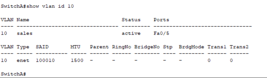
验证测试:验证已创建了Vlan 10,并将0/5端口已划分到Vlan 10中。
SwitchA#show vlan id 10
SwitchA#show vlan id 10VLAN Name Status Ports---- -------------------------------- --------- -------------------------------10 sales active Fa0/5VLAN Type SAID MTU Parent RingNo BridgeNo Stp BrdgMode Trans1 Trans2---- ----- ---------- ----- ------ ------ -------- ---- -------- ------ ------10 enet 100010 1500 - - - - - 0 0SwitchA#
第二步:在交换机SwitchA上创建Vlan 20,并将0/15端口划分到Vlan 20中。
SwitchA#configure terminalEnter configuration commands, one per line. End with CNTL/Z.SwitchA(config)#vlan 20SwitchA(config-vlan)#name technicalSwitchA(config-vlan)#exitSwitchA(config)#interface fastethernet 0/15SwitchA(config-if)#switchport access vlan 20SwitchA(config-if)#exitSwitchA(config)#exitSwitchA#%SYS-5-CONFIG_I: Configured from console by console

验证测试:验证已创建了Vlan 20,并将0/15端口已划分到Vlan 20中。
SwitchA#show vlan id 20
SwitchA#show vlan id 20VLAN Name Status Ports---- -------------------------------- --------- -------------------------------20 technical active Fa0/15VLAN Type SAID MTU Parent RingNo BridgeNo Stp BrdgMode Trans1 Trans2---- ----- ---------- ----- ------ ------ -------- ---- -------- ------ ------20 enet 100020 1500 - - - - - 0 0SwitchA#

第三步:在交换机SwitchA上将与SwitchB相连的端口(假设为0/24端口)定义为tag vlan模式。
SwitchA#configure terminalEnter configuration commands, one per line. End with CNTL/Z.SwitchA(config)#interface fastethernet 0/24SwitchA(config-if)#switchport mode trunkSwitchA(config-if)#exitSwitchA(config)#exitSwitchA#%SYS-5-CONFIG_I: Configured from console by consoleSwitchA#

验证测试:验证fastethernet 0/24端口已被设置为tag vlan模式。
show interfaces fastethernet 0/24 switchport
SwitchA#show interfaces fastethernet 0/24 switchportName: Fa0/24Switchport: EnabledAdministrative Mode: trunkOperational Mode: downAdministrative Trunking Encapsulation: dot1qOperational Trunking Encapsulation: dot1qNegotiation of Trunking: OnAccess Mode VLAN: 1 (default)Trunking Native Mode VLAN: 1 (default)Voice VLAN: noneAdministrative private-vlan host-association: noneAdministrative private-vlan mapping: noneAdministrative private-vlan trunk native VLAN: noneAdministrative private-vlan trunk encapsulation: dot1qAdministrative private-vlan trunk normal VLANs: noneAdministrative private-vlan trunk private VLANs: noneOperational private-vlan: noneTrunking VLANs Enabled: ALLPruning VLANs Enabled: 2-1001Capture Mode DisabledCapture VLANs Allowed: ALLProtected: falseAppliance trust: noneSwitchA#

第四步:在第二台交换机上把交换机命名为SwitchB并在交换机上创建Vlan 10,并将0/5端口划分到Vlan 10中。
SwitchB#enableSwitchB#configure terminalEnter configuration commands, one per line. End with CNTL/Z.SwitchB(config)#hostname SwitchBSwitchB(config)#vlan 10SwitchB(config-vlan)#name salesSwitchB(config-vlan)#exitSwitchB(config)#interface fastethernet 0/5SwitchB(config-if)#switchport access vlan 10SwitchB(config-if)#exitSwitchB(config)#exitSwitchB#%SYS-5-CONFIG_I: Configured from console by consoleSwitchB#

验证测试:验证已在SwitchB上创建了Vlan 10,并将0/5端口已划分到Vlan 10中。
SwitchB#show vlan id 10
SwitchB#show vlan id 10VLAN Name Status Ports---- -------------------------------- --------- -------------------------------10 sales active Fa0/5VLAN Type SAID MTU Parent RingNo BridgeNo Stp BrdgMode Trans1 Trans2---- ----- ---------- ----- ------ ------ -------- ---- -------- ------ ------10 enet 100010 1500 - - - - - 0 0SwitchB#

第五步:在交换机SwitchB上将与SwitchA相连的端口(假设为0/24端口)定义为tag vlan模式。
SwitchB#configure terminalEnter configuration commands, one per line. End with CNTL/Z.SwitchB(config)#interface fastethernet 0/24SwitchB(config-if)#switchport mode trunkSwitchB(config-if)#exitSwitchB(config)#exitSwitchB#%SYS-5-CONFIG_I: Configured from console by consoleSwitchB#

验证测试:验证fastethernet 0/24端口已被设置为tag vlan模式。
SwitchB#show interfaces fastEthernet 0/24 switchport
SwitchB#show interfaces fastethernet 0/24 switchportName: Fa0/24Switchport: EnabledAdministrative Mode: trunkOperational Mode: downAdministrative Trunking Encapsulation: dot1qOperational Trunking Encapsulation: dot1qNegotiation of Trunking: OnAccess Mode VLAN: 1 (default)Trunking Native Mode VLAN: 1 (default)Voice VLAN: noneAdministrative private-vlan host-association: noneAdministrative private-vlan mapping: noneAdministrative private-vlan trunk native VLAN: noneAdministrative private-vlan trunk encapsulation: dot1qAdministrative private-vlan trunk normal VLANs: noneAdministrative private-vlan trunk private VLANs: noneOperational private-vlan: noneTrunking VLANs Enabled: ALLPruning VLANs Enabled: 2-1001Capture Mode DisabledCapture VLANs Allowed: ALLProtected: falseAppliance trust: noneSwitchB#

第六步:验证PC1与PC3能互相通信,但PC2与PC3不能互相通信。
SwitchA>enableSwitchA#configure terminalEnter configuration commands, one per line. End with CNTL/Z.SwitchA(config)#interface FastEthernet0/4SwitchA(config-if)#SwitchA(config-if)#exitSwitchA(config)#interface FastEthernet0/5SwitchA(config-if)#exitSwitchA(config)#int vlan 10SwitchA(config-if)#ip address 192.168.10.254 255.255.255.0SwitchA(config-if)#exitSwitchA(config)#int vlan 20SwitchA(config-if)#ip address 192.168.20.254 255.255.255.0SwitchA(config-if)#exitSwitchA(config)#exitSwitchA#%SYS-5-CONFIG_I: Configured from console by consoleSwitchA#

第八步:将PC1和PC3的默认网关设置为192.168.10.254,IP分别为:192.168.10.11、192.168.10.33,将PC2的默认网关设置为192.168.20.254,IP为192.168.20.22。
PC1

PC3

PC2

第九步:测试结果
不同VLAN内的主机可以互相PING通
PC>ping 192.168.10.33 !在PC1的命令行方式下验证能Ping通PC3 。Pinging 192.168.10.33 with 32 bytes of data:Reply from 192.168.10.33: bytes=32 time<10ms TTL=128Reply from 192.168.10.33: bytes=32 time<10ms TTL=128Reply from 192.168.10.33: bytes=32 time<10ms TTL=128Reply from 192.168.10.33: bytes=32 time<10ms TTL=128Ping statistics for 192.168.10.33:Packets: Sent = 4, Received = 4, Lost = 0 (0% loss),Approximate round trip times in milli-seconds:Minimum = 0ms, Maximum = 0ms, Average = 0msPC>ping 192.168.10.33 !在PC2的命令行方式下验证不能Ping通PC3 。Pinging 192.168.10.33 with 32 bytes of data:Request timed out.Request timed out.Request timed out.Request timed out.Ping statistics for 192.168.10.33:Packets: Sent = 4, Received = 0, Lost = 4 (100% loss),Approximate round trip times in milli-seconds:Minimum = 0ms, Maximum = 0ms, Average = 0ms

若有收获,就点个赞吧
0 人点赞
