Timing diagrams are UML interaction diagrams used to show interactions when a primary purpose of the diagram is to reason about time. Timing diagrams focus on conditions changing within and among lifelines along a linear time axis. Timing diagrams describe behavior of both individual classifiers and interactions of classifiers, focusing attention on time of events causing changes in the modeled conditions of the lifelines.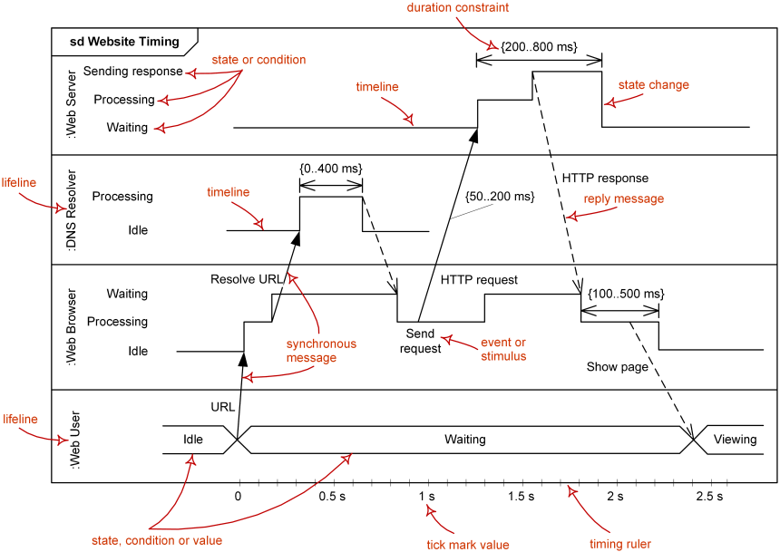
Major elements of timing UML diagram - lifeline, timeline, state or condition, message, duration constraint, timing ruler.
You can find some timing diagram examples here:
- Medical domain - Stages of Alzheimer’s Disease
- User Experience - Website Latency
Lifeline
Lifeline is a named element which represents an individual participant in the interaction. While parts and structural features may have multiplicity greater than 1, lifelines represent only one interacting entity. See lifeline from sequence diagrams for details.
Lifeline on the timing diagrams is represented by the name of classifier or the instance it represents. It could be placed inside diagram frame or a “swimlane”.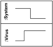
Lifelines representing instances of System and VirusState or Condition Timeline
Timing diagram could show states of the participating classifier or attribute, or some testable conditions, such as a discrete or enumerable value of an attribute.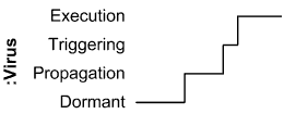
Timeline shows Virus changing its state between Dormant, Propagation, Triggering and Execution state
UML also allows the state/condition dimension be continuous. It could be used in scenarios where entities undergo continuous state changes, such as temperature or density.Duration Constraint
Duration constraint is an interval constraint that refers to a duration interval. The duration interval is duration used to determine whether the constraint is satisfied.
The semantics of a duration constraint is inherited from constraints. If constraints are violated, traces become negative which means that system is considered as failed.
Duration constraint is shown as some graphical association between a duration interval and the constructs that it constrains.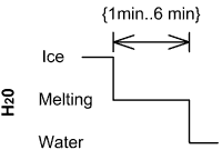
Ice should melt into water in 1 to 6 minutesTime Constraint
Time constraint is an interval constraint that refers to a time interval. The time interval is time expression used to determine whether the constraint is satisfied.
The semantics of a time constraint is inherited from constraints. All traces where the constraints are violated are negative traces, i.e., if they occur, the system is considered as failed.
Time constraint is shown as graphical association between a time interval and the construct that it constrains. Typically this graphical association is a small line, e.g., between an occurrence specification and a time interval.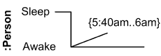
Person should wake up between 5:40 am and 6 amDestruction Occurrence
Destruction occurrence is a message occurrence which represents the destruction of the instance described by the lifeline. It may result in the subsequent destruction of other objects that this object owns by composition. No other occurrence may appear after the destruction event on a given lifeline.Notation
The destruction event is depicted by a cross in the form of an X at the end of a timeline.
Virus lifeline is terminatedHistory
Complete UML name of the occurrence is destruction occurrence specification. Until UML 2.4 it was called destruction event, and earlier - stop.

若有收获,就点个赞吧
0 人点赞
