UML Deployment Diagrams
Deployment diagram shows execution architecture of systems that represent the assignment (deployment) of software artifacts to deployment targets (usually nodes).
Nodes represent either hardware devices or software execution environments. They could be connected through communication paths to create network systems of arbitrary complexity. Artifacts represent concrete elements in the physical world that are the result of a development process and are deployed on nodes.
Note, that components were directly deployed to nodes in UML 1.x deployment diagrams. In UML 2.x artifacts are deployed to nodes, and artifacts could manifest (implement) components. So components are now deployed to nodes indirectly through artifacts.
The following nodes and edges are typically drawn in a UML deployment diagram: deployment, artifact, association between artifacts, dependency between artifacts, component, manifestation, node, device, execution environment, composition of nodes, communication path, deployment specification, deployment specification dependency, deployment specification association.
You can find some deployment diagrams examples here:
- Web application deployment
- Web application manifestation
- Multilayered load balancing
- Clustered deployment of J2EE web application
- Apple iTunes deployment
Android application deployment
Manifestation
Manifestation is an abstraction relationship which represents concrete physical rendering (implementation) of one or more model elements by an artifact or utilization of the model elements in the construction or generation of the artifact. An artifact manifests one or more model elements.
Note, that since UML 2.0 artifacts can manifest any packageable elements, not just components as it was in previous versions of UML.
The artifact owns the manifestations, each representing the utilization of a packageable element.
Specific profiles are expected to stereotype the manifestation relationship to indicate particular forms of manifestation. For example, «tool generated» and «custom code» might be two manifestations for different classes embodied in an artifact.
A manifestation is notated in the same way as abstraction, i.e. as a dashed line with an open arrow head directed from artifact to packageable element, (e.g. to component or package) and is labeled with the keyword «manifest».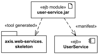
EJB component UserService and skeleton of web services
are manifested (implemented) by EJB module user-service.jar artifact
In UML 1.x, the concept of manifestation was referred to as implementation and annotated as «implement». Since this was one of the many uses of the word “implementation” this has been replaced in UML 2.x by «manifest».Deployment Target
Artifacts are deployed to deployment targets. Deployment target is the location for a deployed artifact.
UML 2.4 definition of deployment target
Instance specification was extended in UML 2.0 to allow instance of a node to be deployment target in a deployment relationship.
Property was also extended in UML 2.0 with the capability of being a deployment target in a deployment relationship. This enables modeling the deployment to hierarchical nodes that have properties functioning as internal parts.
Deployment target owns the set of deployments that target it.
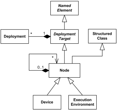
Deployment target has no specific notation by itself, see notations for subclasses.Node
Node is a deployment target which represents computational resource upon which artifacts may be deployed for execution.
Node is shown as a perspective, 3-dimensional view of a cube.

Application Server Node
Node is associated with deployments of artifacts and indirectly with packageable elements that are involved in the manifestations by the artifact that is deployed on the node.
Nodes can be interconnected with communication paths. Communication paths can be defined between nodes such as application server and database server to define the possible communication paths between the nodes. Specific network topologies can then be defined through links between node instances.
Node is specialized by:-
Hierarchical Node
Hierarchical nodes can be modeled using composition or by defining an internal structure. Internal structure of the node is defined in terms of parts and connectors. Parts of the node could be only nodes.

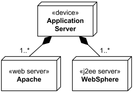
Application server box runs several web servers and J2EE servers
Execution environment is usually part of a general node or «device» which represents the physical hardware environment on which this execution environment resides. Execution environments can be nested (e.g., a database execution environment may be nested in an operating system execution environment).
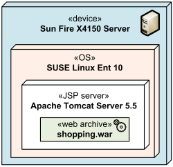
Several execution environments nested into server device
Execution environment instances are assigned to node instances by using composite associations between nodes and execution environments, where the execution environment plays the role of the part.Device
A device is a node which represents a physical computational resource with processing capability upon which artifacts may be deployed for execution.
A device is rendered as a node (perspective, 3-dimensional view of a cube) annotated with keyword «device».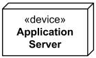
Application Server device
UML provides no standard stereotypes for devices. Examples of non-normative stereotypes for devices are: «application server»
- «client workstation»
- «mobile device»
- «embedded device»
Device may be depicted using custom icon. Profiles, stereotypes, and tagged values could be used to provide custom icons and properties for the devices.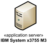
Application Server device depicted using custom icon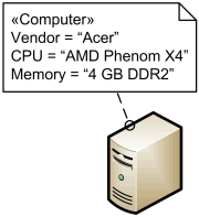
Computer stereotype with tags applied to Device class.
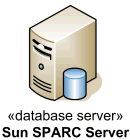
Database Server device depicted using custom icon

Mobile smartphone device depicted using custom icon
Devices may be complex (i.e., they may consist of other devices) where a physical machine is decomposed into its elements, either through namespace ownership or through attributes that are typed by devices.
Execution Environment
An execution environment is a (software) node that offers an execution environment for specific types of components that are deployed on it in the form of executable artifacts. Components of the appropriate type are deployed to specific execution environments.
Execution environment implements a standard set of services that components require at execution time (at the modeling level these services are usually implicit). For each deployment of component, aspects of these services may be determined by properties in a deployment specification for a particular kind of execution environment.
Execution environment is notated the same way as a node (perspective, 3-dimensional view of a cube), annotated with the standard UML stereotype «executionEnvironment».
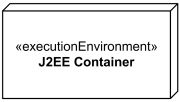
Execution environment - J2EE Container
This «executionEnvironment» is pesky sesquipedalian to use. UML provides no other standard stereotypes for execution environments. Examples of reasonable non-normative stereotypes are:
- «OS»
- «workflow engine»
- «database system»
- «J2EE container»
- «web server»
- «web browser»
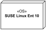
Linux Operating System Execution Environment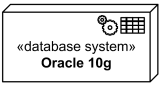
Oracle 10g DBMS Execution Environment
An execution environment can optionally have an explicit interface of system level services that can be used by the deployed elements, in those cases where the modeler wants to make the execution environment software execution environment services explicit.
Communication Path
A communication path is association between two deployment targets, through which they are able to exchange signals and messages.
Communication path is notated as association, and it has no additional notation compared to association.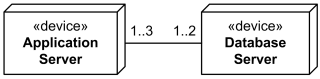
Communication path between several application servers and database servers.
Note, that when deployment targets are some physical devices, communication path will typically represent a physical connection between the nodes.
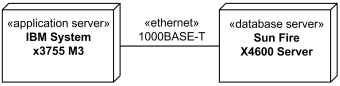
Gigabit Ethernet as communication path between application and database servers.
When deployment targets are execution environments, communication path will typically represent some protocol.
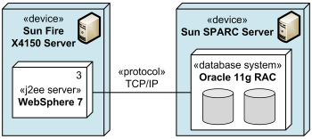
TCP/IP protocol as communication path between J2EE server and database system.
Deployment
A deployment is a dependency relationship which describes allocation (deployment) of an artifact to a deployment target. Deployment could be also defined at instance level - as allocation of specific artifact instance to the specific instance of deployment target.
A component deployment is deployment of one or more artifacts or artifact instances, optionally parameterized by a deployment specification.
It is not very clear why UML defines deployment as a dependency, and not as an association or just a directed relationship. The major contradiction is that dependency in UML does not have any runtime implications, and is defined in terms of the model elements, not in terms of their instances. At the same time UML 2.4 allows and shows examples of instances of artifacts deployed to instances of nodes.
Deployment could be shown as a dependency that is drawn from the artifact (supplier) to the deployment target (client) and is labeled with «deploy». Note, that dependency usually points from the client to the supplier, i.e. in the direction opposite to what is recommended by UML 2.4 for deployment. On the other hand, UML specification allows to change direction for a dependency based on user’s stipulations.
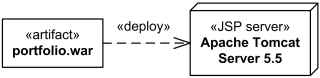
J2EE web application archive portfolio.war
deployed on Apache Tomcat JSP server.
At the “instance level” instances of artifacts could be deployed to specific instances of the deployment target. The underlining of the name of artifact instance may be omitted.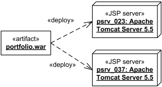
J2EE web application archive portfolio.war deployed
on two instances of Apache Tomcat JSP server - psrv_023 and psrv_037.
For modeling complex deployment target models consisting of nodes with a composite structure defined through “parts,” a property (that functions as a part) may also be the target of a deployment.
Deployment could be shown with deployed artifacts contained by a deployment target.
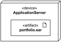
The portfolio.ear artifact deployed on application server.
Deployment could be shown using textual list of deployed artifacts within a deployment target.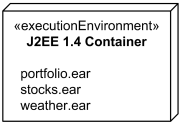
The portfolio.ear, stocks.ear, weather.ear artifacts deployed in J2EE 1.4 container.
Deployment could be shown within a rectangular frame with deployment name in a compartment in the upper left corner. The long form name for the diagram heading is deployment and abbreviated form is dep.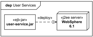
User Services deployment shown in the diagram frame.
Deployment Specification
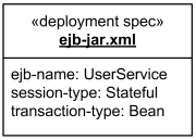
A deployment specification is an artifact that specifies a set of deployment properties that determine execution parameters of a component artifact that is deployed on a node. A deployment specification can be aimed at a specific type of container for components.
A deployment specification is a general mechanism to parameterize a deployment relationship, as is common in various hardware and software technologies. The deployment specification element is expected to be extended in specific component profiles. Non-normative examples of the standard stereotypes that a profile might add to deployment specification are, for example, «concurrencyMode» with tagged values {thread, process, none}, or «transactionMode» with tagged values {transaction, nestedTransaction, none}.
A deployment specification at specification level is rendered as a classifier rectangle with optional deployment properties in a compartment.
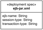
The ejb-jar.xml deployment specification
An artifact that reifies or implements deployment specification properties at instance level is a deployment descriptor. A deployment descriptor is rendered as a classifier rectangle with the name underlined and with deployment properties having specific values in a compartment.
The ejb-jar.xml deployment descriptor
An instance of a deployment specification with specific values for deployment properties may be contained in a complex artifact.
Deployment Specification Dependency
A deployment specification could be displayed as a classifier rectangle attached to a component artifact using a regular dependency arrow pointing to deployed artifact.
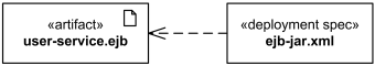
The ejb-jar.xml deployment specification for user-service.ejb artifact.
Deployment Specification Association
Deployment specification could be associated with the deployment of a component artifact on a node. In this case deployment specification could be shown as a classifier rectangle attached to the deployment.
Note, that UML 2.4 specification shows this association as a dashed line (while association is normally displayed as solid line.)
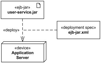
The ejb-jar.xml deployment specification attached to deployment.

若有收获,就点个赞吧
0 人点赞
