UML Component Diagrams
Component diagram shows components, provided and required interfaces, ports, and relationships between them. This type of diagrams is used in Component-Based Development (CBD) to describe systems with Service-Oriented Architecture (SOA).
Component-based development is based on assumptions that previously constructed components could be reused and that components could be replaced by some other “equivalent” or “conformant” components, if needed.
The artifacts that implement component are intended to be capable of being deployed and re-deployed independently, for instance to update an existing system.
Components in UML could represent
- logical components (e.g., business components, process components), and
- physical components (e.g., CORBA components, EJB components, COM+ and .NET components, WSDL components, etc.),
along with the artifacts that implement them and the nodes on which they are deployed and executed. It is anticipated that profiles based around components will be developed for specific component technologies and associated hardware and software environments.
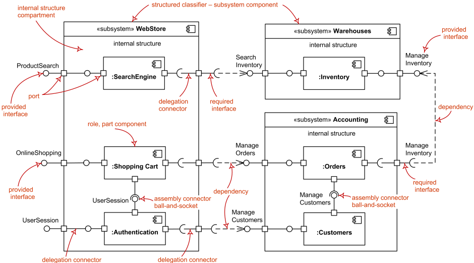
The following nodes and edges are typically drawn in a component diagram: component, interface, provided interface, required interface, class, port, connector, artifact, component realization, dependency, usage. These major elements are shown on the picture below.
The major elements of UML component diagram - component, provided interface, required interface, port, connectors.

