All robots, and our Bionic robot dog in particular, are complex electromechanical systems, comprised of multiple different components working all together. Just by looking at it, it’s hard to say how it can perform advanced movement functions. In this lesson we’re going to have an in-depth look at the modules that Bittle is made of and how they’re all interconnected.
Main components
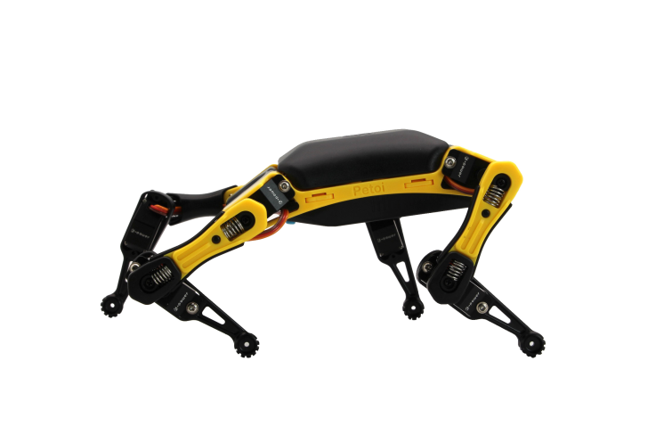
Here are the main components you can see when you look at Bittle:
- servos in every joint, that needs to be moved, namely shoulder and hip joints and head pan joint
- battery installed under the belly
- mainboard with control chip and some modules under black cover
Servos are motors, that can be precisely controlled to be turned to a certain angle. A servo is very similar to electric motor - in fact it IS an electric motor with a controller chip, a potentiometer and gears for reducing speed all packed inside of plastic casing.
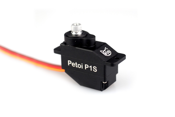
Potentiometer can be used to measure the angle of rotation of the shaft - and using control circuit we can move servo shaft to precise degree, unlike with simple DC motor, where we can only control the direction and speed. All that makes servos uniquely useful in robots applications.
Battery
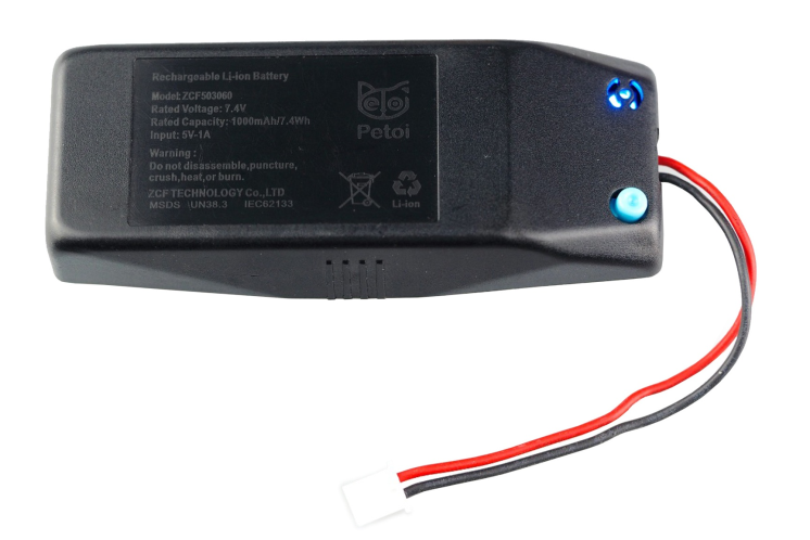
The battery used in Bittle is a lithium-ion battery. A lithium-ion battery is a lightweight, high-power battery used in computers and mobile phones. That makes it useful for devices that should be lightweight. Lithium-ion batteries work by the movement of lithium ions through a membrane (thin sheet that allows some substances to pass through).
Mainboard
After you lift the back cover, you will be able to see the top of the mainboard.
Due to the update and iteration of the product, there are two different versions of the mainboard of the Bittle kit. You can judge which model your Bittle motherboard is based on the silkscreen on the upper left corner of the front of the mainboard.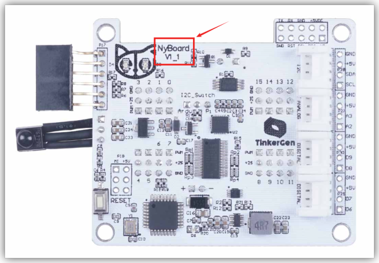
The picture shows the new board NyBoard V1_1
Front of the old board NyBoard V1_0: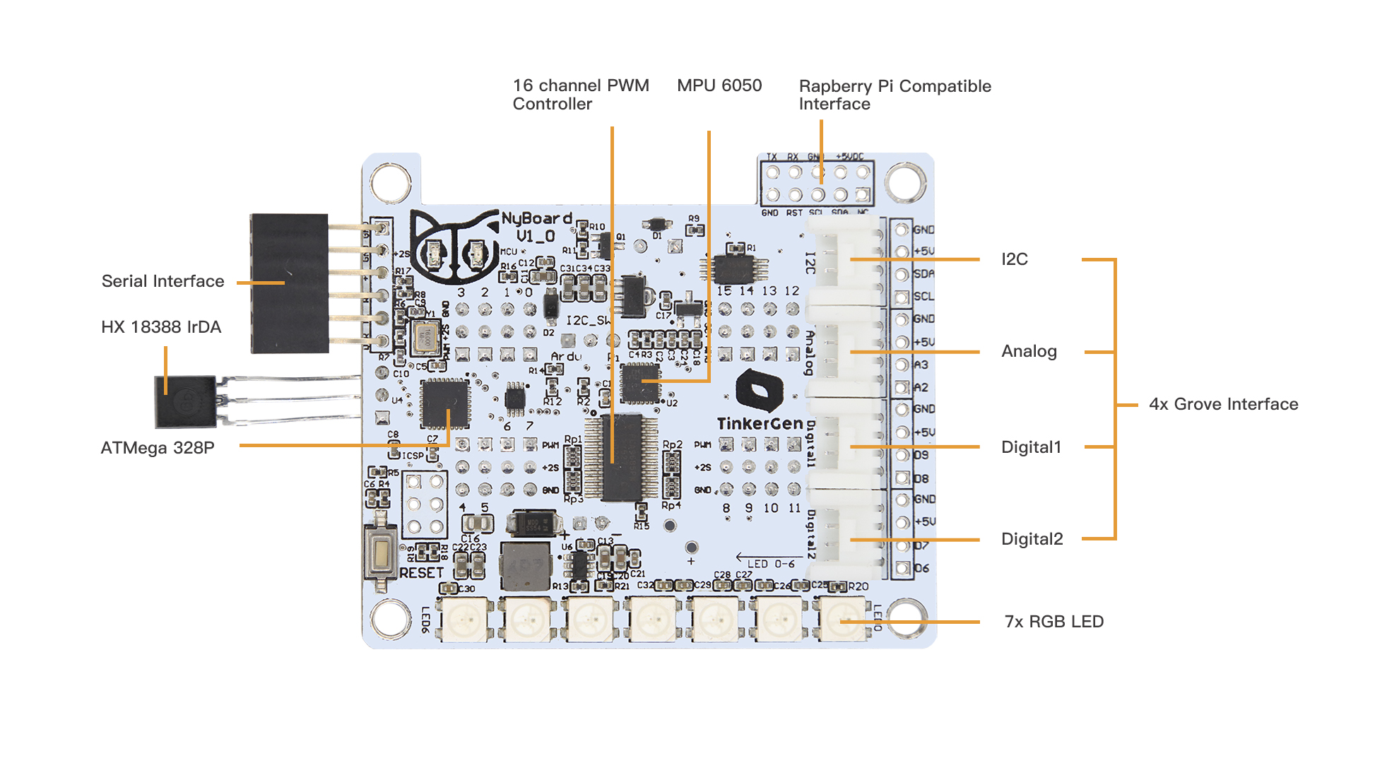
Back of the old board NyBoard V1_0: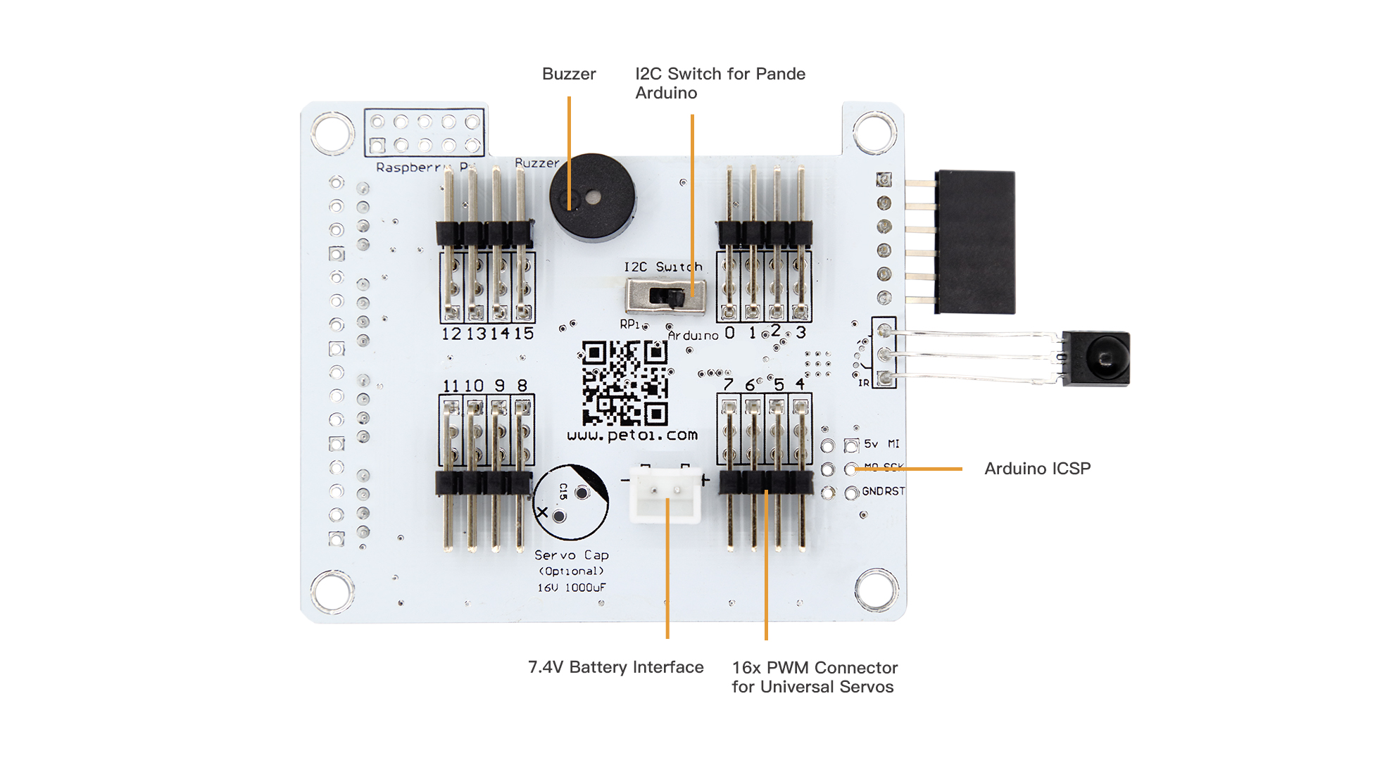
Front of the new board NyBoard V1_1: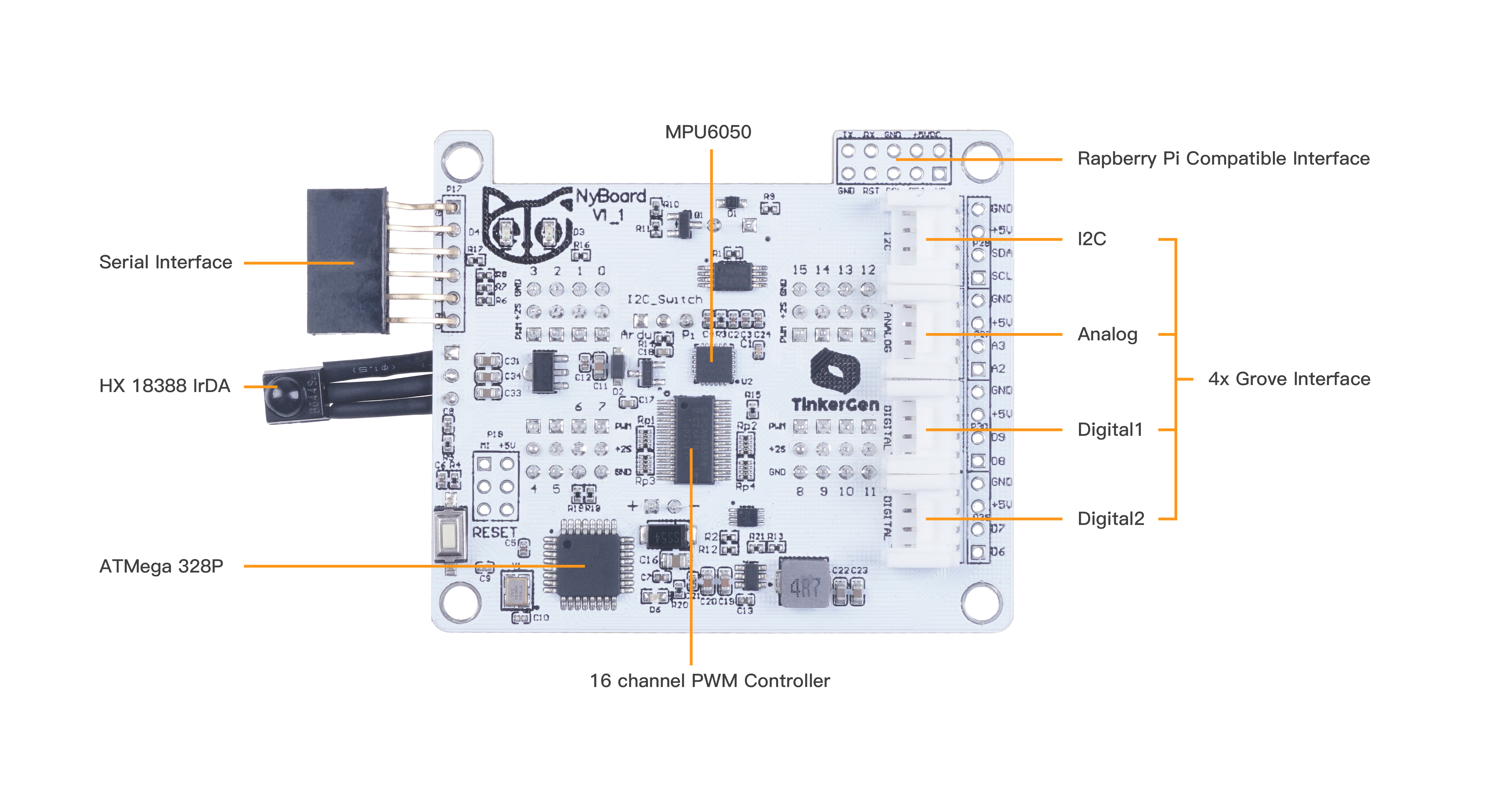
The back of the new board NyBoard V1_1: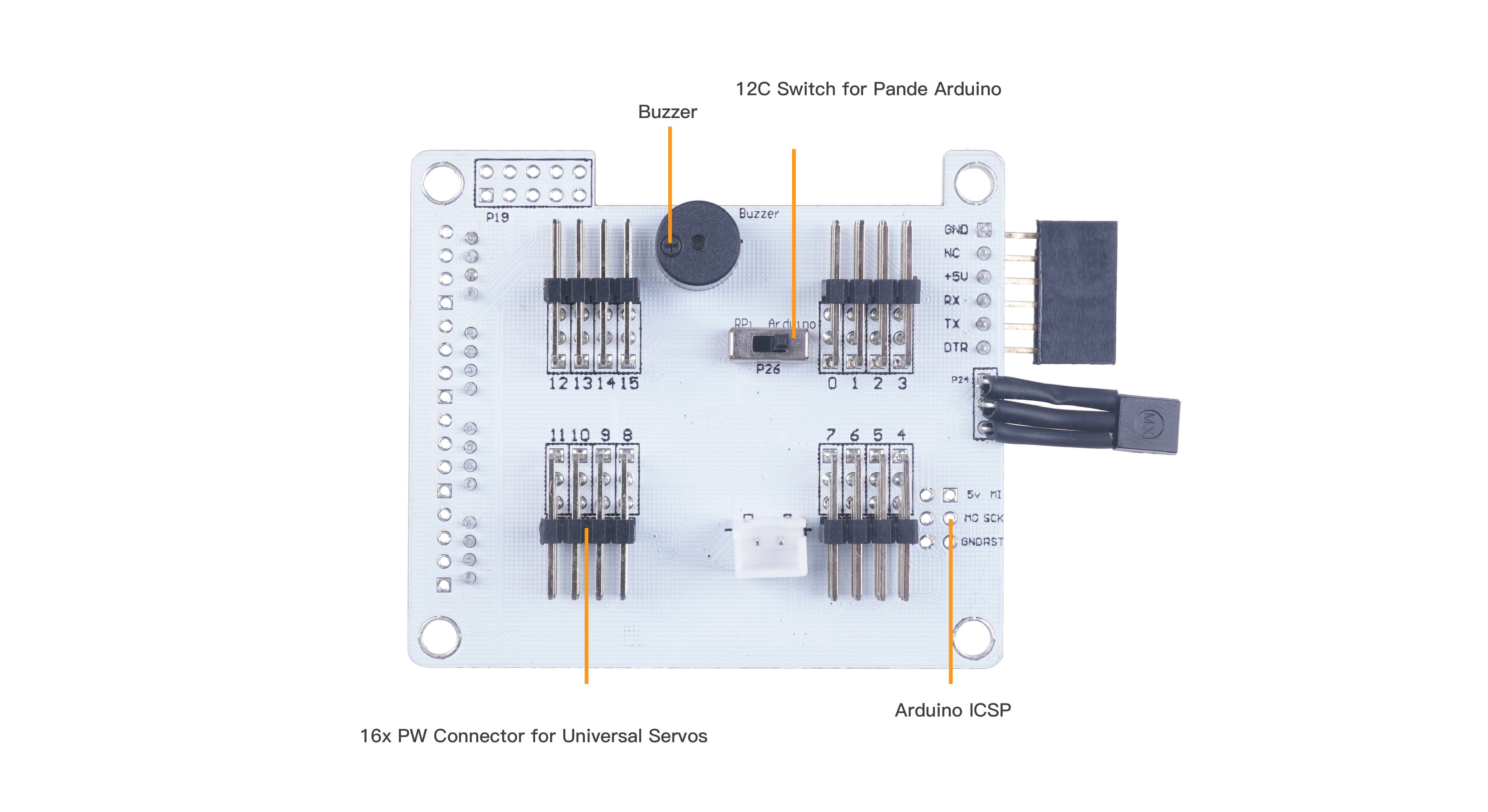
In the center of the board you can see another chip, PCA9685, which is used for controlling the servos. You can think of main control chip as the brain and servo driver chip as a spinal cord in mammals, responsible for motor coordination.
Grove connectors
Additionally, on top of the board you can see four Grove connectors: two digital, one analog, and one I2C bus connector. Digital signal can only be 0 or 1, signifying the presence of absence of voltage in the circuit. Examples of digital modules include, but not limited to:
Button
Infrared Line Follower
Ultrasonic Ranger
Electromagnet
RGB LED
Analog signal on the other hand can be a voltage ranging from 0 to operating voltage of the board. Examples of analog modules include, but not limited to:
Temperature sensor
Sound sensor
Water level sensor
Soil humidity sensor
Finally an I2C bus connector allows us to connect a wide range of I2C devices to Bittle. I2C is a serial communication protocol, that can be described as similar to USB (which stands Universal Serial Bus). Multiple modules can be connected to I2C bus in parallel, since it employs addressing system. Examples of analog modules include, but not limited to:
I2C Color Sensor
Accelerometer
Barometer
EMG Detector
Grove connectors have four pins - two for power(ground and voltage)and two for signal. Most of Grove modules however use just one wire for signal, so when connecting modules that use just one wire, choose the upper pin number For example when connecting to Grove port D6-D7, you should choose D6.
Neopixel RGB LED
Finally, you also can see seven LEDs on top of the board.These are Neopixel RGB LEDs, each one of them can be addressed individually and its color can be changed. They are very useful for debugging and just look shiny!

若有收获,就点个赞吧
0 人点赞
