实例

基本配置
首先进入系统视图,进入系统视图之后就可以配置路由器了system-view 回车Enter system view, return user view with Ctrl+Z.修改路由器的名称[Huawei]sysname R2[R2]配置接口[R2]interface Vlanif 1[R2-Vlanif1][R2-Vlanif1]ip address 192.168.1.1 24或者[R2-Vlanif1]ip address 192.168.1.1 255.255.255.0[R2-Vlanif1]删除IP地址undo ip address查看接口地址[R2-Vlanif1]display this[V200R003C00]#interface Vlanif1ip address 192.168.1.1 255.255.255.0#return[R2-Vlanif1]退出接口继续其他的配置[R2-Vlanif1]quit[R2]配置GigabitEthernet接口进入GigabitEthernet接口[R2]interface GigabitEthernet 0/0/0[R2-GigabitEthernet0/0/0]配置ip地址[R2-GigabitEthernet0/0/0]ip address 20.1.1.1 24Apr 19 2022 20:26:18-08:00 R2 %%01IFNET/4/LINK_STATE(l)[4]:The line protocol IPon the interface GigabitEthernet0/0/0 has entered the UP state.[R2-GigabitEthernet0/0/0]
配置路由器R1
<Huawei>system-viewEnter system view, return user view with Ctrl+Z.[Huawei]sys[Huawei]sysname R1[R1][R1]interface GigabitEthernet 0/0/0[R1-GigabitEthernet0/0/0]ip add[R1-GigabitEthernet0/0/0]ip address 20.1.1.2 24Apr 19 2022 20:28:53-08:00 R1 %%01IFNET/4/LINK_STATE(l)[0]:The line protocol IPon the interface GigabitEthernet0/0/0 has entered the UP state.[R1-GigabitEthernet0/0/0][R1-GigabitEthernet0/0/0]ping 20.1.1.1PING 20.1.1.1: 56 data bytes, press CTRL_C to breakReply from 20.1.1.1: bytes=56 Sequence=1 ttl=255 time=90 msReply from 20.1.1.1: bytes=56 Sequence=2 ttl=255 time=20 msReply from 20.1.1.1: bytes=56 Sequence=3 ttl=255 time=20 msReply from 20.1.1.1: bytes=56 Sequence=4 ttl=255 time=30 msReply from 20.1.1.1: bytes=56 Sequence=5 ttl=255 time=20 ms--- 20.1.1.1 ping statistics ---5 packet(s) transmitted5 packet(s) received0.00% packet lossround-trip min/avg/max = 20/36/90 ms[R1-GigabitEthernet0/0/0][R1-GigabitEthernet0/0/0]quit[R1]inter[R1]interface g[R1]interface GigabitEthernet 0/0/1[R1-GigabitEthernet0/0/1][R1-GigabitEthernet0/0/1]ip address 20.1.2.2 24Apr 19 2022 20:31:35-08:00 R1 %%01IFNET/4/LINK_STATE(l)[1]:The line protocol IPon the interface GigabitEthernet0/0/1 has entered the UP state.[R1-GigabitEthernet0/0/1]
配置路由器R3
<Huawei>system-viewEnter system view, return user view with Ctrl+Z.[Huawei]sys[Huawei]sysname R3[R3][R3]interface GigabitEthernet 0/0/0[R3-GigabitEthernet0/0/0]ip address 20.1.2.1 24[R3-GigabitEthernet0/0/0]Apr 19 2022 20:32:56-08:00 R3 %%01IFNET/4/LINK_STATE(l)[0]:The line protocol IPon the interface GigabitEthernet0/0/0 has entered the UP state.[R3-GigabitEthernet0/0/0][R3-GigabitEthernet0/0/0]ping 20.1.2.2PING 20.1.2.2: 56 data bytes, press CTRL_C to breakReply from 20.1.2.2: bytes=56 Sequence=1 ttl=255 time=140 msReply from 20.1.2.2: bytes=56 Sequence=2 ttl=255 time=40 msReply from 20.1.2.2: bytes=56 Sequence=3 ttl=255 time=20 msReply from 20.1.2.2: bytes=56 Sequence=4 ttl=255 time=50 msReply from 20.1.2.2: bytes=56 Sequence=5 ttl=255 time=40 ms--- 20.1.2.2 ping statistics ---5 packet(s) transmitted5 packet(s) received0.00% packet lossround-trip min/avg/max = 20/58/140 ms[R3-GigabitEthernet0/0/0][R3]interface Vlanif 1Apr 19 2022 20:34:06-08:00 R3 %%01IFNET/4/IF_STATE(l)[1]:Interface Vlanif1 has turned into UP state.[R3-Vlanif1]ip address 192.168.2.1 2Error: The specified IP address is invalid.[R3-Vlanif1]ip address 192.168.2.1 24Apr 19 2022 20:34:46-08:00 R3 %%01IFNET/4/LINK_STATE(l)[2]:The line protocol IPon the interface Vlanif1 has entered the UP state.[R3-Vlanif1]ping 192.168.2.2PING 192.168.2.2: 56 data bytes, press CTRL_C to breakReply from 192.168.2.2: bytes=56 Sequence=1 ttl=128 time=110 msReply from 192.168.2.2: bytes=56 Sequence=2 ttl=128 time=20 msReply from 192.168.2.2: bytes=56 Sequence=3 ttl=128 time=10 msReply from 192.168.2.2: bytes=56 Sequence=4 ttl=128 time=20 msReply from 192.168.2.2: bytes=56 Sequence=5 ttl=128 time=30 ms--- 192.168.2.2 ping statistics ---5 packet(s) transmitted5 packet(s) received0.00% packet lossround-trip min/avg/max = 10/38/110 ms[R3-Vlanif1]
查看配置:
<R1>display current-configuration
保存配置:
<R1>saveThe current configuration will be written to the device.Are you sure to continue? (y/n)[n]:yIt will take several minutes to save configuration file, please wait.......Configuration file had been saved successfullyNote: The configuration file will take effect after being activated
确认是否保存:
<R1>dirDirectory of flash:/Idx Attr Size(Byte) Date Time(LMT) FileName0 drw- - Apr 19 2022 12:00:41 dhcp1 -rw- 121,802 May 26 2014 09:20:58 portalpage.zip2 -rw- 2,263 Apr 19 2022 12:21:01 statemach.efs3 -rw- 828,482 May 26 2014 09:20:58 sslvpn.zip4 -rw- 352 Apr 19 2022 12:39:21 private-data.txt5 -rw- 583 Apr 19 2022 12:39:21 vrpcfg.zip1,090,732 KB total (784,448 KB free)<R1> 看到 vrpcfg.zip 说明保存成功
设置静态路由
网络畅通的前提是:有去有回
路由器默认只知道直连的网段:没有直连的需要哦管理员添加静态路由
配置R2路由
查看路由<R2>display ip routing-tableRoute Flags: R - relay, D - download to fib------------------------------------------------------------------------------Routing Tables: PublicDestinations : 10 Routes : 10Destination/Mask Proto Pre Cost Flags NextHop Interface20.1.1.0/24 Direct 0 0 D 20.1.1.1 GigabitEthernet0/0/020.1.1.1/32 Direct 0 0 D 127.0.0.1 GigabitEthernet0/0/020.1.1.255/32 Direct 0 0 D 127.0.0.1 GigabitEthernet0/0/0127.0.0.0/8 Direct 0 0 D 127.0.0.1 InLoopBack0127.0.0.1/32 Direct 0 0 D 127.0.0.1 InLoopBack0127.255.255.255/32 Direct 0 0 D 127.0.0.1 InLoopBack0192.168.1.0/24 Direct 0 0 D 192.168.1.1 Vlanif1192.168.1.1/32 Direct 0 0 D 127.0.0.1 Vlanif1192.168.1.255/32 Direct 0 0 D 127.0.0.1 Vlanif1255.255.255.255/32 Direct 0 0 D 127.0.0.1 InLoopBack0Direct:直连<R2>添加网络20.1.2.0 24的静态路由<R2>ip route-static 20.1.2.0 24 20.1.1.2添加网络192.168.2.0 24的静态路由[R2]ip route-static 192.168.2.0 24 20.1.1.2
配置R1路由
添加网络192.168.1.0 24的静态路由<R2>ip route-static 192.168.1.0 24 20.1.1.1添加网络192.168.2.0 24的静态路由[R2]ip route-static 192.168.2.0 24 20.1.2.1
配置R3路由
添加网络192.168.1.0 24的静态路由<R2>ip route-static 192.168.1.0 24 20.1.2.2添加网络20.1.1.0 24的静态路由[R2]ip route-static 20.1.1.0 24 20.1.2.2<R3>system-viewEnter system view, return user view with Ctrl+Z.[R3]ip route-static 20.1.1.0 24 20.1.2.2[R3]ip route-static 192.168.1.0 24 20.1.2.2
结果验证
Ping 192.168.2.2: 32 data bytes, Press Ctrl_C to breakRequest timeout!From 192.168.2.2: bytes=32 seq=2 ttl=125 time=47 msFrom 192.168.2.2: bytes=32 seq=3 ttl=125 time=15 msFrom 192.168.2.2: bytes=32 seq=4 ttl=125 time=31 msFrom 192.168.2.2: bytes=32 seq=5 ttl=125 time=31 ms--- 192.168.2.2 ping statistics ---5 packet(s) transmitted4 packet(s) received20.00% packet lossround-trip min/avg/max = 0/31/47 ms
PC>tracert 192.168.2.2traceroute to 192.168.2.2, 8 hops max(ICMP), press Ctrl+C to stop1 192.168.1.1 47 ms <1 ms 15 ms2 20.1.1.2 63 ms 31 ms 31 ms3 20.1.2.1 47 ms 31 ms 32 ms4 192.168.2.2 46 ms 32 ms 47 msPC>
实例
实例01
如下图所示,新增一台公网IP电脑
其地址分配如下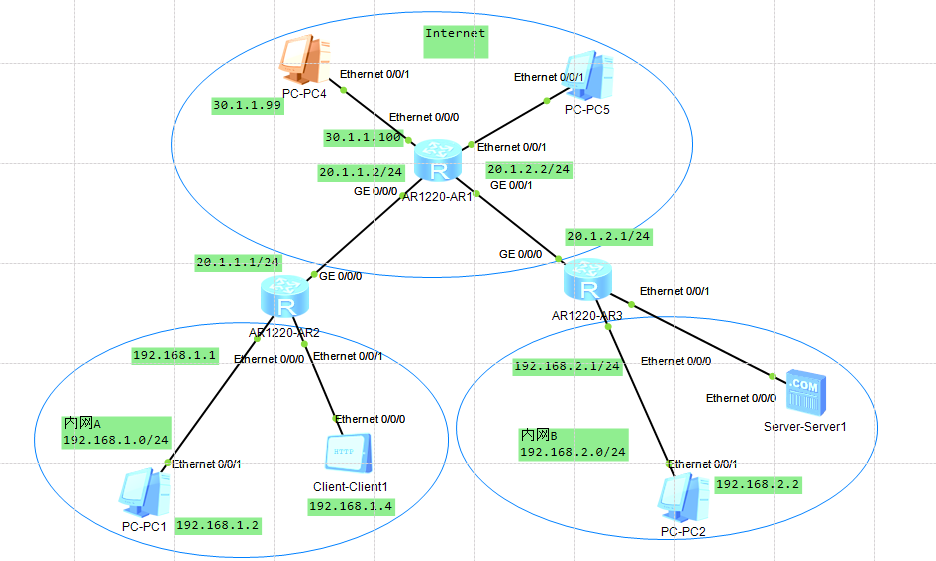
PC端设置如下: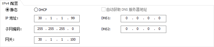
AR1设置如下:
// 进入系统<R1>system-viewEnter system view, return user view with Ctrl+Z.// 进入接口1[R1]interface Vlanif 1// 设置IP地址[R1-Vlanif1]ip address 30.1.1.100 24// 查看接口是否设置成功[R1-Vlanif1]display this[V200R003C00]#interface Vlanif1ip address 30.1.1.100 255.255.255.0#return[R1-Vlanif1]// 退出[R1]quit[R1]quit// 保存<R1>saveThe current configuration will be written to the device.Are you sure to continue? (y/n)[n]:yIt will take several minutes to save configuration file, please wait.........Configuration file had been saved successfullyNote: The configuration file will take effect after being activated
# 添加网络30.1.1.99 32的静态路由# 由于其跟路由器中的接口处于同一网段,故不用单独配置路由表
AR2设置如下:
# 添加网络30.1.1.99 32的静态路由<R2>system-viewEnter system view, return user view with Ctrl+Z.[R2]ip route-static 30.1.1.99 32 20.1.1.2// 测试[R2]ping 30.1.1.99PING 30.1.1.99: 56 data bytes, press CTRL_C to breakReply from 30.1.1.99: bytes=56 Sequence=1 ttl=127 time=30 msReply from 30.1.1.99: bytes=56 Sequence=2 ttl=127 time=30 msReply from 30.1.1.99: bytes=56 Sequence=3 ttl=127 time=30 msReply from 30.1.1.99: bytes=56 Sequence=4 ttl=127 time=30 msReply from 30.1.1.99: bytes=56 Sequence=5 ttl=127 time=40 ms--- 30.1.1.99 ping statistics ---5 packet(s) transmitted5 packet(s) received0.00% packet lossround-trip min/avg/max = 30/32/40 ms[R2]
实例02
新增一个公网IP,为期配置防火墙,如下所示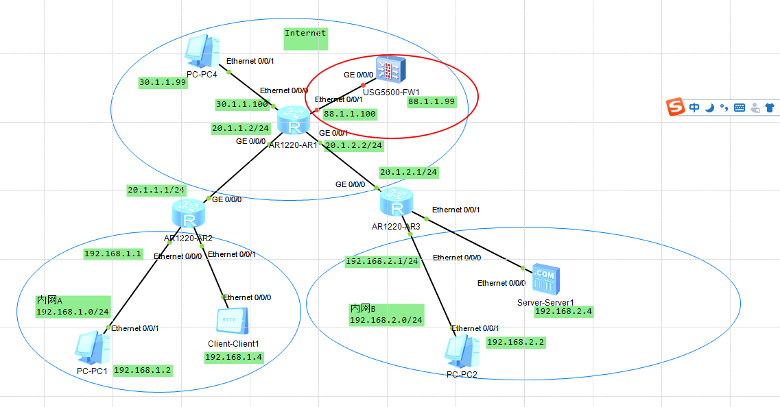

AR1设置如下:
[Huawei]vlan 2[Huawei-vlan10]int vlanif 2[Huawei-Vlanif10]ip address 88.1.1.1 24[Huawei-Vlanif10]int e0/0/0[Huawei-Ethernet0/0/0]port link-type access[Huawei-Ethernet0/0/0]port default vlan 2//查看R1]interface Vlanif 10[R1-Vlanif10]displ[R1-Vlanif10]display this[V200R003C00]#interface Vlanif10ip address 88.1.1.1 24#return[R1-Vlanif10]
防火墙设置
[SRG]int g0/0/0[SRG-GigabitEthernet0/0/0]ip address 88.1.1.2 24

若有收获,就点个赞吧
0 人点赞
