一、模型建立
根据单摆模型,建立以下模型,如下图:
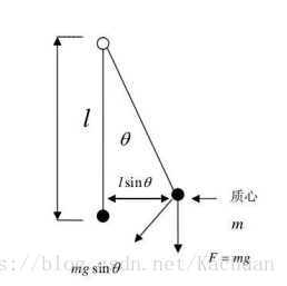
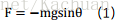
忽略空气阻力的情况下,当物体离开平衡位置后,物体会受到竖直向下的重力和沿着悬挂线向上方向的拉力的合力作用,使得物体在平衡位置做往返运动。该合力又称为恢复力,如下:
其中,悬线与竖直方向夹角为θ,与物体运动方向夹角为 π- θ,F方向与物体运动方向相切,指向平衡位置。
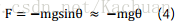
又由极限,可知,当θ较小时,有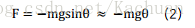实际中,物体除了受到回复力F的作用外,还受到空气阻力F阻的作用,从而最终会静止在平衡位置。而运动中空气阻力的大小与物体运动速度大小成正比,该比例由阻尼系数k表示,而阻力方向与运动速度方向相反。此时物体在运动方向上所受合力如下: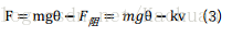因此,对于单摆模型,其保持平衡需耀具备以下条件:受到与偏移方向相反的回复力的作用<br /> 受到与物体运动方向相反的阻尼力的作用<br />对于两轮平衡车,可以简化为倒立摆模型,如下:<br />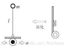
而对于倒立摆模型,其受力如下: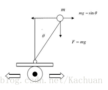
如单摆模型,可知物体受到回复力为:
 <br />但由于此时回复力方向与物体平衡位置方向相反,因此物体反而会加速离开平衡位置。为了让物体回到平衡位置,即保持与竖直方向平行,可以让倒立摆向与物体偏离方向相反的方向做加速运动,加速度为a。此时倒立摆受力如图: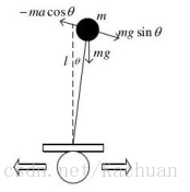倒立摆将受到惯性力: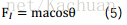不计空气阻力时,倒立摆运动方向上所受合力为: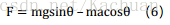当偏移角较小时,有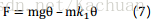
其中,取近似 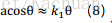
当k1>g时,物体在运动方向上受到与回复力方向相反的力。此时,在空气阻力作用下,物体将在平衡位置往返,最终回到平衡位置。而为了让物体尽快回到平衡位置,可以通过外加阻尼力,其大小与物体偏离平衡位置的速度成正比,比例系数为k2,方向相反,则有: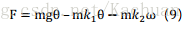因此,可以通过外力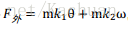,来使小车保持平衡。而外力的来源即是通过控制小车车轮的加速度,使得小车获得相应的惯性力。其中k1会使得小车向物体倾倒的相反方向做加速运动,k1过大过小将导致小车直接偏离品平衡位置的方向而倾倒;k2使得小车能够尽快回到平衡位置,k2过大过小时,都会影响小车回到平衡位置的调节时间。
二、系统分析
第一部分从建立物理模型的角度出发,通过物理定律推导得到物理等式。
但光有理论,没有结合实际也会觉得难以下手,因此第二部分结合实践,从系统的角度出发,结合物理等式对系统的控制做进一步分析。
首先,还是从物理定律出发,得到物理等式。如图,考虑一个可移动小车上的倒立摆模型,其中杆的长度为L,不计杆的质量,杆的末端有一个质量为m的小球,θ(t)该摆偏离垂直位置的角度,g是重力加速度,s(t)是小车相对于某个参考点的位置,a(t)是小车的加速度,x(t)代表由任何扰引起的角加速度。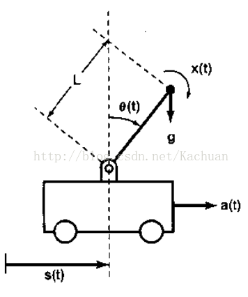
对杆上小球受力分析,有

此时,Fθ(t)方向为垂直于杆,沿着倾倒方向。
根据运动学知识,有
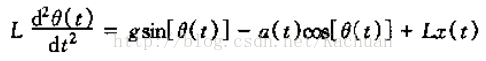
注意,角速度要转为线速度
反馈就是利用一个系统的输出去控制或改变系统的输入。反馈除了能提供一个误差校正的机理而减小系统对扰动以及系统数学模型误差的灵敏度以外,反馈的另一个重要特性在于使一个固有的不稳定系统稳定的能力上。考虑以上倒立摆模型,如果小车保持静止不动的话,倒立摆一定会倒下来。但通过移动小车,让小车根据倒立摆偏离竖直方向的角度来回移动,最终可也让倒立摆达到动态平衡,即与竖直方向角度为0。显然,稳定倒立摆问题也就是设计一个反馈系统。该反馈系统使小车移动以保持倒立摆成垂直状态。
对于连续时间LTI反馈系统的一般结构可以通过上图表示,此时系统函数为
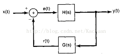 假定θ(t)很小,即对于该模型,考虑该模型是在接近垂直位置的时候的动态特性,此时可以做如下近似
sin[ θ(t) ]≈θ(t) ,cos[ θ(t) ]≈1
当小车静止时,即a(t)=0。求拉普拉斯变换,可得系统函数为
由上式可知,有极点s=g/l 或s=-g/l ,即系统在右半平面有一个极点,意味着该系统是不稳定的。(稳定:系统的单位冲激相应绝对可和。)因此,在不进行反馈控制时,该系统为一个LTI因果不稳定系统。也就是说,在小车静止不动时,任何由x(t)所造成的微小角扰动都将导致偏离垂直方向的角度进一步增大。
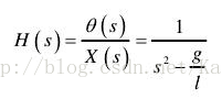
为了让小车以适当的方式移动,以摆在垂直位置,设想采用比例反馈,即 a(t) = Kθ(t)
同样假定θ(t)很小,使得该系统可以近似满足LTI的特性。
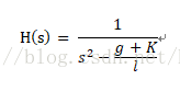
观察发现,此时对于系统函数H(s),其在s平面的右半平面至少存在一个极点,因此系统依旧不稳定。考虑加入比例加微分反馈 ,此时该系统函数变为二阶函数,如下
可得系统的两个极点 。根据奈奎斯特稳定判断依据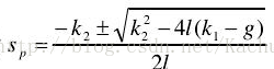 ,要使得系统稳定,则两个极点都必须位于s平面的左半平面,此时有k1>g,k2>0。
综上所述,平衡车控制核心是一个角度PD控制器,有

三、改进
实际上,由于结构设计或组装上的不合理,小车物理重心总与竖直方向总存在一个夹角(或者说与地面不是保持垂直关系),小车在这一倾角作用下,在水平方向上受到一重力分量而会进行加速运动,最终倾倒而无法保持平衡。因此,需要在原先角度PD控制的基础上,加入速度PI控制,控制小车的速度。至于为什么是速度PI控制?阅读资料,仍然无法完全理解,其中讲到速度计算中存在着噪声影响,如果对该速度信号做微分计算时,会放大噪声的影响。(或者讲到小车为非最小相位系统,速度调节的时间常数要选取比较大??不是很理解,如果有更好的见解,也请多多指教哈)
速度PI控制如下:

总而言之,小车的控制可以归结为两个PID控制,一个为角度PD控制,一个为速度PI控制,为了保证系统的实时显示,两个PID控制必须放在中断程序中执行,而角度PD控制的频率要比速度PI控制的频率高。(具体还不是很清楚??)
#include "Wire.h"const uint8_t IMUAddress = 0x68; // AD0 is logic low on the PCBconst uint16_t I2C_TIMEOUT = 100; // Used to check for errors in I2C communicationint p;int receive_x;uint8_t i2cWrite(uint8_t registerAddress, uint8_t data, bool sendStop) {return i2cWrite(registerAddress, &data, 1, sendStop); // Returns 0 on success}uint8_t i2cWrite(uint8_t registerAddress, uint8_t *data, uint8_t length, bool sendStop) {Wire.beginTransmission(IMUAddress);Wire.write(registerAddress);Wire.write(data, length);uint8_t rcode = Wire.endTransmission(sendStop); // Returns 0 on successif (rcode) {Serial.print(F("i2cWrite failed: "));Serial.println(rcode);}return rcode; // See: http://arduino.cc/en/Reference/WireEndTransmission}uint8_t i2cRead(uint8_t registerAddress, uint8_t *data, uint8_t nbytes) {uint32_t timeOutTimer;Wire.beginTransmission(IMUAddress);Wire.write(registerAddress);uint8_t rcode = Wire.endTransmission(false); // Don't release the busif (rcode) {Serial.print(F("i2cRead failed: "));Serial.println(rcode);return rcode; // See: http://arduino.cc/en/Reference/WireEndTransmission}Wire.requestFrom(IMUAddress, nbytes, (uint8_t)true); // Send a repeated start and then release the bus after readingfor (uint8_t i = 0; i < nbytes; i++) {if (Wire.available())data[i] = Wire.read();else {timeOutTimer = micros();while (((micros() - timeOutTimer) < I2C_TIMEOUT) && !Wire.available());if (Wire.available())data[i] = Wire.read();else {Serial.println(F("i2cRead timeout"));return 5; // This error value is not already taken by endTransmission}}}return 0; // Success}/******************************************************///2560 pin map 引脚定义好即可,然后改变一下PID的几个值(kp,kd,ksp,ksi)即可,剩下的全部都是固定的程序,//可能小车会有一点重心不在中点的现象,加一下角度值或者减一点即可//至于每个MPU6050的误差,自己调节一下即可,不是很难//调试时先将速度环的ksp,ksi=0,调到基本可以站起来,然后可能会出现倒,或者自动跑起来的时候加上速度环//这时就会很稳定的站起来,然后用小力气的手推不会倒。int ENA=9;int ENB=10;int IN1=7;int IN2=4;int IN3=5;int IN4=6;int MAS,MBS;int KEY = 2;/* IMU Data */double accX, accY, accZ;double gyroX, gyroY, gyroZ;int16_t tempRaw;double gyroXangle, gyroYangle; // Angle calculate using the gyro onlydouble compAngleX, compAngleY; // Calculated angle using a complementary filterdouble kalAngleX, kalAngleY; // Calculated angle using a Kalman filteruint8_t i2cData[14]; // Buffer for I2C datauint32_t timer;unsigned long lastTime;/***************************************/double P[2][2] = {{ 1, 0 },{ 0, 1 }};double Pdot[4] ={ 0,0,0,0};static const double Q_angle=0.001, Q_gyro=0.003, R_angle=0.5,dtt=0.005,C_0 = 1;double q_bias, angle_err, PCt_0, PCt_1, E, K_0, K_1, t_0, t_1;double angle,angle_dot,aaxdot,aax;double position_dot,position_dot_filter,positiono;/*-------------Encoder---------------*/#define LF 0#define RT 1//The balance PIDfloat kp,kd,ksp,ksi;int Lduration,Rduration;boolean LcoderDir,RcoderDir;const byte encoder0pinA = 2;const byte encoder0pinB = 12;//7;byte encoder0PinALast;const byte encoder1pinA = 3;const byte encoder1pinB = 13;//8;byte encoder1PinALast;int RotationCoder[2];int turn_flag=0;float move_flag=0;float right_need = 0, left_need = 0;;int pwm;int pwm_R,pwm_L;float range;float range_error_all;float wheel_speed;float last_wheel;float error_a=0;void Kalman_Filter(double angle_m,double gyro_m){angle+=(gyro_m-q_bias) * dtt;Pdot[0]=Q_angle - P[0][1] - P[1][0];Pdot[1]=- P[1][1];Pdot[2]=- P[1][1];Pdot[3]=Q_gyro;P[0][0] += Pdot[0] * dtt;P[0][1] += Pdot[1] * dtt;P[1][0] += Pdot[2] * dtt;P[1][1] += Pdot[3] * dtt;angle_err = angle_m - angle;PCt_0 = C_0 * P[0][0];PCt_1 = C_0 * P[1][0];E = R_angle + C_0 * PCt_0;K_0 = PCt_0 / E;K_1 = PCt_1 / E;t_0 = PCt_0;t_1 = C_0 * P[0][1];P[0][0] -= K_0 * t_0;P[0][1] -= K_0 * t_1;P[1][0] -= K_1 * t_0;P[1][1] -= K_1 * t_1;angle+= K_0 * angle_err;q_bias += K_1 * angle_err;angle_dot = gyro_m-q_bias;//也许应该用last_angle-angle}void setup() {Wire.begin();Serial.begin(9600);pinMode(KEY, INPUT);pinMode(IN1, OUTPUT);pinMode(IN2, OUTPUT);pinMode(IN3, OUTPUT);pinMode(IN4, OUTPUT);pinMode(ENA, OUTPUT);pinMode(ENB, OUTPUT);TWBR = ((F_CPU / 400000L) - 16) / 2; // Set I2C frequency to 400kHzi2cData[0] = 7; // Set the sample rate to 1000Hz - 8kHz/(7+1) = 1000Hzi2cData[1] = 0x00; // Disable FSYNC and set 260 Hz Acc filtering, 256 Hz Gyro filtering, 8 KHz samplingi2cData[2] = 0x00; // Set Gyro Full Scale Range to ±250deg/si2cData[3] = 0x00; // Set Accelerometer Full Scale Range to ±2gwhile (i2cWrite(0x19, i2cData, 4, false)); // Write to all four registers at oncewhile (i2cWrite(0x6B, 0x01, true)); // PLL with X axis gyroscope reference and disable sleep modewhile (i2cRead(0x75, i2cData, 1));if (i2cData[0] != 0x68) { // Read "WHO_AM_I" registerSerial.println(F("Error reading sensor"));while (1);}else {Serial.println(F("success reading sensor"));}delay(20); // Wait for sensor to stabilizewhile (i2cRead(0x3B, i2cData, 6));accX = (i2cData[0] << 8) | i2cData[1];accY = (i2cData[2] << 8) | i2cData[3];accZ = (i2cData[4] << 8) | i2cData[5];double roll = atan2(accX, accZ) * RAD_TO_DEG;EnCoderInit();timer = micros();//The balance PID*************************************************************************kp= 33;//24.80;43kd= 2.1 ; //9.66;1.4ksp= 0;//4.14;8.5ksi= 0;//0.99; 0.55;2.1}void EnCoderInit(){//pinMode(8,INPUT);///pinMode(9,INPUT);attachInterrupt(LF, LwheelSpeed, RISING);attachInterrupt(RT, RwheelSpeed, RISING);}void pwm_calculate(){unsigned long now = millis(); // 当前时间(ms)int Time = now - lastTime;int range_error;range += (Lduration + Rduration) * 0.5;range *= 0.9;range_error = Lduration - Rduration;range_error_all += range_error;wheel_speed = range - last_wheel;//wheel_speed = constrain(wheel_speed,-800,800);//Serial.println(wheel_speed);last_wheel = range;pwm = (angle + 0.825) * kp + angle_dot * kd + range * ksp + wheel_speed * ksi;if(pwm > 255)pwm = 255;if(pwm < -255)pwm = -255;if(turn_flag == 0){pwm_R = pwm + range_error_all;pwm_L = pwm - range_error_all;}else if(turn_flag == 1) //左转{pwm_R = pwm ; //Direction PID controlpwm_L = pwm + left_need * 68;range_error_all = 0; //clean}else if(turn_flag == 2){pwm_R = pwm + right_need * 68; //Direction PID controlpwm_L = pwm ;range_error_all = 0; //clean}Lduration = 0;//cleanRduration = 0;lastTime = now;}void PWMD(){if(pwm>0){digitalWrite(IN1, HIGH);digitalWrite(IN2, LOW);digitalWrite(IN3, LOW);digitalWrite(IN4, HIGH);}else if(pwm<0){digitalWrite(IN1, LOW);digitalWrite(IN2, HIGH);digitalWrite(IN3, HIGH);digitalWrite(IN4, LOW);}int PWMr = abs(pwm);int PWMl = abs(pwm);analogWrite(ENB, max(PWMl,60)); //PWM调速a==0-255 51analogWrite(ENA, max(PWMr,60)); //PWM调速a==0-255 54}void LwheelSpeed(){if(digitalRead(encoder0pinB))Lduration++;else Lduration--;}void RwheelSpeed(){if(digitalRead(encoder1pinB))Rduration--;else Rduration++;}void control(){if(Serial.available()){int val;val=Serial.read();switch(val){case 'w':if(move_flag<5)move_flag += 0.5;else move_flag = 0;break;case 's':if(move_flag<5)move_flag -= 0.5;else move_flag = 0;Serial.println("back");break;case 'a':turn_flag = 1;left_need = 0.6;Serial.println("zuo");break;case 'd':turn_flag = 2;right_need = 0.6;Serial.println("you");break;case 't':move_flag=0;turn_flag=0;right_need = left_need = 0;Serial.println("stop");break;default:break;}}}//调试时先将速度环的ksp,ksi=0,调到基本可以站起来,然后可能会出现倒,或者自动跑起来的时候加上速度环//这时就会很稳定的站起来,然后用小力气的手推不会倒。void change(){while (Serial.available() > 0) {receive_x = Serial.parseInt();char ccc = Serial.read();if (ccc == 'P') {kp=receive_x/100.0;Serial.print("kp:");Serial.println(kp);}else if(ccc == 'D') {kd=receive_x/100.0;Serial.print("kd:");Serial.println(kd);}else if(ccc == 'K') {ksp=receive_x/100.0;Serial.print("ksp:");Serial.println(ksp);}else if(ccc == 'S') {ksi=receive_x/100.0;Serial.print("ksi:");Serial.println(ksi);}//kp= 200; P //24.80;43//kd= 2.0 ; D //9.66;1.4//ksp= 0; K //4.14;8.5//ksi= 0;S //0.99; 0.550,2.1}}void loop(){//control();change();while (i2cRead(0x3B, i2cData, 14));accX = ((i2cData[0] << 8) | i2cData[1]);//accY = ((i2cData[2] << 8) | i2cData[3]);accZ = ((i2cData[4] << 8) | i2cData[5]);//gyroX = (i2cData[8] << 8) | i2cData[9];gyroY = (i2cData[10] << 8) | i2cData[11];//gyroZ = (i2cData[12] << 8) | i2cData[13];//Serial.print(accX);Serial.print(" ");//Serial.print(accZ);Serial.print(" ");//Serial.println(gyroY);double dt = (double)(micros() - timer) / 1000000; // Calculate delta timetimer = micros();double roll = atan2(accX, accZ) * RAD_TO_DEG - move_flag;//double gyroXrate = gyroX / 131.0; // Convert to deg/sdouble gyroYrate = -gyroY / 131.0; // Convert to deg/s//gyroXangle += gyroXrate * dt; // Calculate gyro angle without any filter//gyroYangle += gyroYrate * dt;Kalman_Filter(roll,gyroYrate);if(abs(angle)<35){//Serial.println(angle); while (Serial.available() > 0) { // 串口收到字符数大于零。pwm_calculate();PWMD();}else{analogWrite(ENB, 0); //PWM调速a==0-255analogWrite(ENA, 0); //PWM调速a==0-255}delay(2);}

若有收获,就点个赞吧
0 人点赞
