STM32L151低功耗模式
默认情况下,系统复位后,控制器运行在RUN模式,此模式下CPU时钟为HCLK
若CPU不需要一直处于运行状态,可设置为其他几种低功耗模式
低功耗模式共有5种:
1低功耗运行 适配器低电压 时钟频率受限 部分外围受限
2睡眠 内核停止 外围保持运行
3低功耗睡眠 内核停止 时钟频率受限 部分外围受限 电源适配器处于低功耗模式 RAM断电 Flash停止
4停止模式 所有时钟停止,电源低功耗运行
5待机模式 内核断电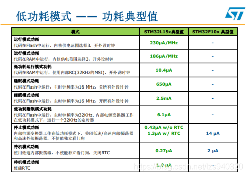
低功耗模式下时钟的特点
APB外设和DMA时钟是可以通过软件关闭的
Low Power modes configuration
低功耗运行模式
=====================================
[..]
The device features 5 low-power modes:
(+) Low power run mode: regulator in low power mode, limited clock frequency,
limited number of peripherals running.
低功耗运行模式:以调节器低功耗模式运行,受限制的时钟频率,受限制的外设运行数
(+) Sleep mode: Cortex-M3 core stopped, peripherals kept running.
睡眠模式:M3内核停止,外围设备保持运行
(+) Low power sleep mode: Cortex-M3 core stopped, limited clock frequency,
limited number of peripherals running, regulator in low power mode.
低功耗运行模式:M3内核停止,受限制的时钟频率,受限制的外设运行数目,调节器低功耗运行
(+) Stop mode: All clocks are stopped, regulator running, regulator in low power mode.
停止模式:全时钟停止,调节器运行,调节器处于低功耗模式
(+) Standby mode: VCORE domain powered off
待机模式:VCORE决定断电
Sleep mode
睡眠模式
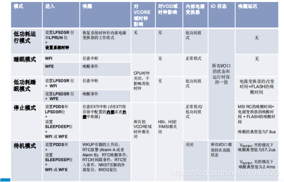
[..](+) Entry:The Sleep mode is entered by using the HAL_PWR_EnterSLEEPMode(PWR_MAINREGULATOR_ON, PWR_SLEEPENTRY_WFx)functions with(++) PWR_SLEEPENTRY_WFI: enter SLEEP mode with WFI instruction(++) PWR_SLEEPENTRY_WFE: enter SLEEP mode with WFE instruction(+) Exit:(++) Any peripheral interrupt acknowledged by the nested vectored interruptcontroller (NVIC) can wake up the device from Sleep mode.
由嵌套向量中断控制器(NVIC)确认的任何外围中断都可以从休眠模式唤醒设备
若通过WFI指令进入睡眠模式,任何外围设备的中断都能唤醒设备
若通过WFE指令进入睡眠模式,MCU通过事件唤醒:
/*** @brief Enters Sleep mode.* @note In Sleep mode, all I/O pins keep the same state as in Run mode.睡眠模式下,全部的IO保持与运行状态相同的状态* @param Regulator: Specifies the regulator state in SLEEP mode.指定休眠状态下的调节器状态* This parameter can be one of the following values:* @arg PWR_MAINREGULATOR_ON: SLEEP mode with regulator ON休眠并且调节器开* @arg PWR_LOWPOWERREGULATOR_ON: SLEEP mode with low power regulator ON休眠并且低功耗调节器开* @param SLEEPEntry: Specifies if SLEEP mode is entered with WFI or WFE instruction.* When WFI entry is used, tick interrupt have to be disabled if not desired as* the interrupt wake up source.* This parameter can be one of the following values:* @arg PWR_SLEEPENTRY_WFI: enter SLEEP mode with WFI instruction* @arg PWR_SLEEPENTRY_WFE: enter SLEEP mode with WFE instruction* @retval None*/
void HAL_PWR_EnterSLEEPMode(uint32_t Regulator, uint8_t SLEEPEntry)
睡眠和低功耗睡眠模式下,CPU内核停止。睡眠模式下,内存接口时钟与其他外围时钟均可以通过软件设定停止。
低功耗睡眠模式下,内存接口模式停止,而且RAM处于掉电模式下,AHB-APB总线被硬件停止
Low power sleep mode
低功耗休眠模式
[..](+) Entry:The Low power sleep mode is entered by using the HAL_PWR_EnterSLEEPMode(PWR_LOWPOWERREGULATOR_ON, PWR_SLEEPENTRY_WFx)functions with() PWR_SLEEPENTRY_WFI: enter SLEEP mode with WFI instruction//以WFI进入休眠() PWR_SLEEPENTRY_WFE: enter SLEEP mode with WFE instruction//以WFE进入休眠(+) The Flash memory can be switched off by using the control bits (SLEEP_PD in the FLASH_ACR register.This reduces power consumption but increases the wake-up time.Flash//内存能通过控制位替换(+) Exit:(++) If the WFI instruction was used to enter Low power sleep mode, any peripheral interruptacknowledged by the nested vectored interrupt controller (NVIC) can wake up the devicefrom Low power sleep mode. If the WFE instruction was used to enter Low power sleep mode,the MCU exits Sleep mode as soon as an event occurs.//若为WFI进入休眠,任意外设中断能够从低功耗休眠模式唤醒设备。如果WFE被用于进入低功耗休眠模式,MCU在一个事件发生后立刻退出休眠。
(1)进入低功耗睡眠模式
进入低功耗睡眠模式,需要配置电压适配器到低功耗模式,同时配合WFI或WFE指令,在这种模式下,Flash存储无效,但是RAM有效。
在这种模式下,系统频率不能超过f_MSI range1
低功耗睡眠模式只有在Vcore在电压范围2(range=1.5V)才能进入
有两种方式进入低功耗睡眠模式:
1、立刻睡眠:若SLEEPONEXIT位清零,一旦执行WFI或WFE,MCU立刻进入低功耗睡眠模式
2、通过事件睡眠:如果SLEEPONEXIT位置1,只有事件的优先级最低,MCU才进入低功耗模式:
①通过FLASH_ACR寄存器的SLEEP_PD位,关闭Flash,这可以降低功耗,不过也会增加唤醒时间
②IP Clock必须通过RCC_APBxENR和RCC_AHBENR寄存器使能或禁止
③系统时钟频率必须降低
④通过软件(LPSDSR bit位设定)强制电压适配器处于低功耗模式
⑤执行WFI/WFE执行,进入睡眠模式
Stop mode
停止模式
[..]The Stop mode is based on the Cortex-M3 deepsleep mode combined with peripheral clock gating. The voltage regulator can be configured either in normal or low-power mode.In Stop mode, all clocks in the VCORE domain are stopped, the PLL, the MSI, the HSI and the HSE RC oscillators are disabled. Internal SRAM and register contents are preserved.To get the lowest consumption in Stop mode, the internal Flash memory also enters low power mode. When the Flash memory is in power-down mode, an additional startup delay is incurred when waking up from Stop mode. To minimize the consumption In Stop mode, VREFINT, the BOR, PVD, and temperature sensor can be switched off before entering Stop mode. They can be switched on again by software after exiting Stop mode using the ULP bit in the PWR_CR register. In Stop mode, all I/O pins keep the same state as in Run mode.(+) Entry:The Stop mode is entered using the HAL_PWR_EnterSTOPMode(PWR_MAINREGULATOR_ON, PWR_SLEEPENTRY_WFI )function with:() Main regulator ON.主调节器开() Low Power regulator ON.断电调节器开() PWR_SLEEPENTRY_WFI: enter SLEEP mode with WFI instruction以WFI进入休眠模式() PWR_SLEEPENTRY_WFE: enter SLEEP mode with WFE instruction以WFE进入休眠模式(+) Exit:(++) By issuing an interrupt or a wakeup event, the MSI RC oscillator is selected as system clock.通过产生一个中断或唤醒事件,MSI RC振荡器会被选择为系统时钟
停止模式基于M3深度睡眠模式与外围时钟门控。电压适配器能够被配置为正常或低功率模式。在停止模式下,所有处于VCORE的时钟都会被停止,PLL,MSI,HSE RC振荡器被禁止。内部SRAM和寄存器被保留。
为了得到停止模式下的最低功耗,内部Flash内存也进入低功耗模式,当闪存处于断电状态下从停止模式启动,会有一个额外的启动延时。VREFINT,BOR,PVD和温度传感器可以在进入停止模式前关闭来最小化停止模式的耗电。它们可以通过使用PWR_CR寄存器的ULP位来再次打开。在停止模式下,全部的IO引脚保持与运行状态相同。
当stop模式被中断打断跳出,或待机模式被reset打断跳出时,MSI会被自动选择为系统时钟。
当设备从stop模式跳出后,MSI信息保持不变,当设备从待机模式跳出后,定时值会被复位为默认的2MHz
停止模式是一种深度睡眠,配合外围时钟选通。电压适配器可以配置为正常或低功耗模式。
停止模式下,Vcore时钟是停止的,PLL、MSI、HSI、HSE RC是停止的,内部的SRAM和寄存器目录是保持的。
若要在stop模式下得到最低功耗,内部flash也要进入低功耗模式,当flash在power down模式,当从stop模式下唤醒后,会有启动延时。闲置状态为低电平时,设置为下拉输入,闲置状态为高电平时,设置为上拉输入。
为了实现功耗最小化,进入stop模式前,Vrefint、BOR、PVD、温度传感器可以关闭,这些外围也是可以再打开的,当从stop模式退出后,通过PWR_CR寄存器中ULP bit位。
在stop模式下,以下外围可以独立编程:IWDG、RTC、LSI RC振荡器、外部32.768k振荡器
STOP模式下:
从stop模式下退出可以通过中断或wakeup事件,退出后,MSI RC振荡器会被选为系统时钟。
需要重新配置系统时钟
Standby mode
待机模式
[..]The Standby mode allows to achieve the lowest power consumption. It is based on the Cortex-M3 deepsleep mode, with the voltage regulator disabled. The VCORE domain is consequently powered off. The PLL, the MSI, the HSI oscillator and the HSE oscillator are also switched off. SRAM and register contents are lost except for the RTC registers, RTC backup registers and Standby circuitry.To minimize the consumption In Standby mode, VREFINT, the BOR, PVD, and temperature sensor can be switched off before entering the Standby mode. They can be switched on again by software after exiting the Standby mode.function.(+) Entry:() The Standby mode is entered using the HAL_PWR_EnterSTANDBYMode() function.(+) Exit:() WKUP pin rising edge, RTC alarm (Alarm A and Alarm B), RTC wakeup,tamper event, time-stamp event, external reset in NRST pin, IWDG reset.唤醒引脚上升沿RTC报警,RTC唤醒,纂改事件,NRST引脚的外部复位信号,IWDG复位
待机模式允许获取最少的电力消耗,它基于M3深度睡眠模式,并且电压调节器禁能。PLL,MSI,HSI振荡器和HSE振荡器也会被关闭。SRAM和寄存器内容会被丢失,除了RTC寄存器、RTC备用寄存器和待机电路。
为了最小化待机电路的消耗,VREFINT,BOR,PVD和温度传感器可以在进入待机模式前关闭。它们可以在退出待机模式后再次打开。

若有收获,就点个赞吧
0 人点赞
