2.1 INTRODUCTION
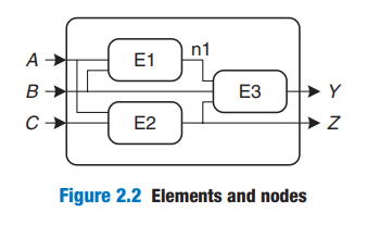
Figure 2.2 illustrates a circuit with three elements, E1, E2, and E3, and six nodes. Nodes A, B, and C are inputs. Y and Z are outputs. n1 is an internal node between E1 and E3.
- Digital circuits
- combinational
- depends only on current inputsmemoryless
- sequential
- ~ on current & previous inputshas memory
Figure 2.3 The symbol
 inside the box indicates that it is implemented using only combinational logic. In this example, the function F is specified to be OR: Y = F(A, B) = A + B. In words, we say that the output Y is a function of the two inputs, A and B—namely, Y = A OR B.
- ~ on current & previous inputshas memory
- combinational
Figure 2.5 full adder, 2 equations specify the function of the outputs
Figure 2.6 A single line with a slash through it and a number next to it to indicate a bus, a bundle of multiple signals.The number specifies how many signals are in the bus. Figure 2.6(a) represents a block of combinational logic with three inputs
and two outputs.

A circuit is combinational if it consists of interconnected circuit elements such that
▸ Every circuit element is itself combinational.
▸ Every node of the circuit is either designated as an input to the circuit or connects to exactly one output terminal of a circuit element.
▸ The circuit contains no cyclic paths: every path through the circuit visits each circuit node at most once.
Example 2.1 COMBINATIONAL CIRCUITS
Which of the circuits in Figure 2.7 are combinational circuits according to the
rules of combinational composition? 
(a) is combinational. It is constructed from two combinational circuit elements (inverters I1 and I2). It has three nodes: n1, n2, and n3. n1 is an input to the circuit and to I1; n2 is an internal node, which is the output of I1 and the input to I2; n3 is the output of the circuit and of I2. (b) is not combinational, because there is a cyclic path: the output of the XOR feeds back to one of its inputs. Hence, a cyclic path starting at n4 passes through the XOR to n5, which returns to n4. (c) is combinational. (d) is not combinational, because node n6 connects to the output terminals of both I3 and I4. (e) is combinational, illustrating two combinational circuits connected to form a larger combinational circuit. (f) does not obey the rules of combinational composition because it has
a cyclic path through the two elements. Depending on the functions of the elements, it may or may not be a combinational circuit.
2.2 BOOLEAN EQUATIONS
2 . 2 . 1 Terminology
Assuming function of 3 variables A, B, C
Literal : e.g.: (\overline:the complementary _form)
_True form : 
Complementary form : 
Product/Implicant : AND of  literals e.g.:
Minterm : A product involving all inputs to a function, e.g.:

Sum : OR of  literals e.g. : A + B
Maxterm : A sum involving all of the inputs to the function. e.g. : 
2 . 2 . 2 Sum-of-Products Form
Truth table of N inputs contains 2N rows. Each row in a truth table is associated with a minterm that is TRUE for that row.

We can write Boolean equation for any truth table by summing each of the minterm for which the output, Y, is TRUE. Called sum-of-products(SOP) canonical form __范式
It is the sum(OR) of product(AND)
e.g.:
Figure 2.8:
Figure 2.9: 
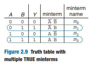
The sum-of-products canonical form can also be written in sigma notation using the summation symbol, Σ
Figure 2.9: or
or
2 . 2 . 3 Product-of-Sums Form
Expressing Boolean Function -> product-of-sums canonical form POS
e.g.:
POS for truth table in Figure 2.13

2.3 BOOLEAN ALGEBRA
Simplify your boolean equations.
Axioms and theorems of Boolean algebra obey the principle of duality 对偶原则. If the symbols 0 and 1 and the operators • (AND) and + (OR) are interchanged, the statement will still be correct. We use the prime symbol (′) to denote the dual of a statement.
2 . 3 . 1 Axioms

Table 2.1 states the axioms of Boolean algebra. These five axioms and their duals define Boolean variables and the meanings of NOT, AND, and OR.
2 . 3 . 2 Theorems of One Variable
‘
2 . 3 . 3 Theorems of Several Variables
2 . 3 . 4 The Truth Behind It All
2 . 3 . 5 Simplifying Equations
2.4 FROM LOGIC TO GATES

若有收获,就点个赞吧
0 人点赞
