Model:
“A Model is an abstraction of the system being studied”
The purpose of building models:
(Existing systme)
- Help clarify what the existing system does
Form discussions on system’s strengths and weaknesses
(New systme)
Help explain the proposed requirements
- Form discussions on design proposals
- Help document the system for implementation
System Modelling Perspectives
System modeling is the process of developing abstract models of a system, with each model presenting a different view or perspective of that system.
External
The context or environment of the system.
Context Model
- Created at the early stage of the requirements engineering
- To know and to decide the boundary of the system being developed
- To establish a high-level view on the interactions between the system and its operational environment without details.
- Use simple block diagrams or empty class diagrams
The elements

Example


Stereotype
A stereotype is UML’s way of attaching extra classifications to model items; it’s one of the ways that UML is made extensible.
- It is used to describe model element
- It is placed close to the element in the diagram
- It uses a pair of << >> to enclose a type, e.g., <
Business Process Model
- Depict how systems are involved in a particular business process
- Use activity diagrams or dedicated Business Process Model and Notation


Interaction
The interactions between a system and its environment/user, or between the components of a system
- User interaction
- Involves user inputs and outputs
- Helps to identify user requirements
- System interaction
- Interactions between the software system being developed and the systems in its environment
- Highlights the communication problems that may arise.
- Component interaction

- If there are some additional behaviors that should be added (maybe conditionally)
- Extended UseCase is defined independently of the extending UseCase
- Extending UseCase may not be meaningful by itself
-
Use Case Dependency — Include
Include is intended to be used:
The including use case may depend on the changes produce by executing the included use cases(s).
- The included use case(s) must be available for the behaviors of the including use case to be completed.
- It can also be used when there are common parts of the behaviors of the two or more use case(s).
Brainstorming
Use Case Dependency — Generalization


Interaction Modelling
Interaction Overview Diagram
Defines interactions through a variant of Activity diagrams; it focuses on the overview of the flow of control.
Communication Diagram
Focuses on interaction between entities of the internal structure and how this corresponds with the message flow.
Sequence Diagram
Describes how message interexchange between several lifelines; the functionalities of sequence diagram and communication diagram are largely the same
Sequence Diagram-Example-Login

Behavioral
The runtime behavior of the system and how it responds to events
Structural
The organization of the system or the structure of the data processed by the system
- Model the organization of a system in terms of functional components and their relationships
- The organization of the system design (static structure)
- The organization of the system when it is executing (dynamic structure)
- Used for discussing and designing the system architecture
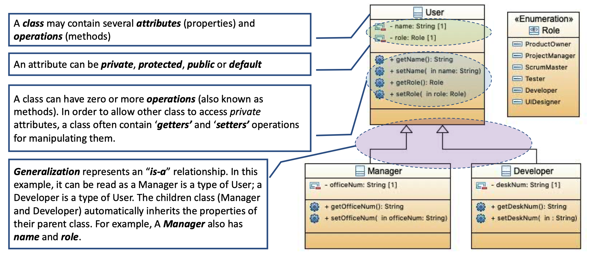
Class diagrams are used for modeling the static structure of a system
Class Diagram
Generalization
Dependency
Realization
Package Diagrams
A Package is considered as a namespace for its members
- When performing analysis, package diagrams are used to organize the artifacts of the development
- Provides encapsulation and containment and supports modularity
- Provides clarity and neat organization in a complex systems development
- Support version control


Example

Deployment Diagrams
Deployment diagram show the relationships between logical and/or physical elements of systems and assets assigned to them.


若有收获,就点个赞吧
0 人点赞
