schema of TCP server
Why does one NGINX worker take all the load?
Attention: Use mulitple address/port is not considered here.
one socket, one worker processone socket, socket sharing,all worker wathes the same fd- use blocking
accept- In older version, exists herd problem. ie: all worker gets waken up but only a portion of them can be succesfull accepted.(In case there are multiple ESTABLISED socket, otherwise only one worker can accept successfully)
- Linux will do proper
FIFO-like round robinload balancing. Each process waiting onaccept()is added to a queue and they will be served connections in order.
- use
epollnone blocking accept- A
LIFObehavior - Problems: Connection are
not evenlybalanced.
- A
- use blocking
multiple socket, multiple worker processes useSO_REUSEPORTbind to the same port.- Cons: more variant and higher latency,and need newer kernel version。
- Pros:simple load balancing。
scoket sharing:
child processes can get acopyof the parent socket(add up the reference counting of a given fd), and can do accept independantly. Under the hood, each bloked process was added to a FIFO queue.
Example:
Nginxusessocket sharingin multiple workers and supportSO_REUSEPORT.Uvicornusessocket sharingin multiple workers mode.
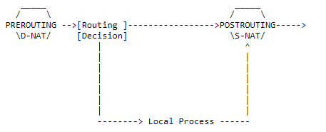
iptables
https://help.ubuntu.com/community/IptablesHowTo
3 tables and 5 chains
- filter
- INPUT/OUTPUT/FORWARD
- nat
- PREROUTING/POSTROUTING
- mangle
iptables -L -nv --line-numbers -t filter/nat/mangle
- receive messages: PREROUTING -> INPUT
- send messages: OUTPUT -> POSTROUTING
- gateway: PREROUTING -> FORWARD -> POSTROUTING
iptables [-t table] COMMAND chain# chan manipulatingCOMMAND-N new chain-X delte chain-E rename chain-P set default policy ACCEPT/DROP/REJECTiptables [-t table] COMMAND chain MAPPING -j ACCEPT/REJECT...# rule manipulatingCOMMAND-A append rule-I insert-D delete-R replace-F flush-Z zero# show-L list rules-n/-v/-x show more info# rule mapping-s source ip-d destination ip-p protocoltcp--sport/--dport/--tcp-flagsudp--sport/--dporticmp--icmp-type-i input interface-o outout interface-m extension mapping rules, man iptables-extensions for detailsmultiport configure at most 15 portsiprangestring use kmp/bm pattern matching algorithm to match packetstime configure time mappingconnlimit set the connection number limits for each client ipstate NEW/ESTABLISHED/INVALID...# action-j/--jumpy set actionDNAT/SNAT/REJECT/MASQUERADE/ACCEPT/DROP
NAT
Network address translation
https://netfilter.org/documentation/HOWTO
SNATSource NAT- MASQUERADE, A specialized SNAT, the —to-source will be set to the ip of the outcoming interface.
DNATDestination NAT- REDIRECT, A specialized DNAT, the —to-destination will be set to the ip of the incoming interface.
- How it works
- Make sure both requests and replies of a certain connection passes the NAT box, thus the NAT box can change the destination address of the response back to the initial source address of the SNATed packets from innernet. This is done by maintaining a mapping that maps
sender ip:porttochanged ip:port.
- Make sure both requests and replies of a certain connection passes the NAT box, thus the NAT box can change the destination address of the response back to the initial source address of the SNATed packets from innernet. This is done by maintaining a mapping that maps
- Tips
- When multiple ip is specified for —to, the least currently used known ip will be choosed. ie: like load-balancing
- SNAT is prefered in the outermost router. As shown below, in router2, SNAT is opened and router1 is set as the gateway for innernet. Thus only router2 will bear the burdon of handling map tables. The point is the router2 knows everything in the innernet while the outernet only knows router2.
- outerner — router2 — router1(gateway) — multiple client in innernet.
- Use -j ACCEPT to create null NAT.
- Implicit source port mapping when masquerading(see link for details). ```bash iptables -t nat // specify chain -A/—append // append rule at the back -I/—insert // insert rule at the front
packet matching rules
-s/—source 192.168.1.1 / node2 / 192.168.1.0/24 -d/—destination 192.168.1.1 / node2 / 192.168.1.0/24 -i/—in-interface / -o/—out-interface // -i for DNAT, vice versa -p/—protocol TCP/UDP —sport/—source-port —dport/—destination-port
extension match rules
man iptables-extensions // check all extensions -m/—match addrtype/ah/bpf/… -m addrtype —src-type LOCAL mactch all packets send by local
ACCEPT
Skip follow up rules if matched
SNAT
-A POSTROUTING -j/—jump SNAT —to/—to-source ip -A POSTROUTING -o eth0 -j SNAT —to 1.2.3.4-1.2.3.6 // change srcip to to 1.2.3.1 or 1.2.3.6 -A POSTROUTING -p tcp -o eth0 -j SNAT —to 1.2.3.4:1-1023 // change srcport 1 or 2 … 1023
Masquerading
-A POSTROUTING -o eth0 -j MASQUERADE // packet routed to eth0 will change src ip to the ip of eth0
DNAT
-A PREROUTING -j/—jump DNAT —to/—to-destination ip -A PREROUTING -i eth0 -j DNAT —to 5.6.7.8 -A PREROUTING -i eth0 -j DNAT —to 5.6.7.8-1.2.3.4 -A PREROUTING -p tcp —dport 80 -i eth0 -j DNAT —to 5.6.7.8:8080
Redirect
commands below do the same thing
-A PREROUTING -i eth1 -p tcp —dport 80 -j REDIRECT —to-port 8080 -A PREROUTING -i eth1 -p tcp —dport 80 -j DNAT —to-destination :8080 -A PREROUTING -i eth1 -p tcp —dport 80 -j DNAT —to-destination ipofeth1:8080
<a name="kR2hW"></a>## NAT types[https://blog.csdn.net/eydwyz/article/details/87364157](https://blog.csdn.net/eydwyz/article/details/87364157)<br />[http://www.cppblog.com/fwxjj/archive/2008/08/14/58823.html](http://www.cppblog.com/fwxjj/archive/2008/08/14/58823.html)- **local tuple**. source address and port of the ip packet sended by innernet client.- outer tuple. altered source address and port by SNAT- target tuple. target address and port of the packet.Whenever a local tuple tries to send packets to a different target tuple.- symmetric NAT will create another map for each unique local-target pair.- cone nat will **reuse** the afore-established local-outer map.Who can communicate with the local tuple?- full cone,- As long as a local-outer map is established before, **all hosts** can send messages to the local tuple through the outer tuple.- address restricted cone.- Only the **address** that has received messages from the local tuple can communicate with local tuple through the outer tuple.- port restricted cone.- Not only the **address** is restricted to be formerly connected, the **port** needs the same requirement.- symmetric- The same as port restricted cone.<a name="O2m7a"></a>#### Checking NAT types1. If the local client is reacheable by udp(if behind a firewall).1. If the lcoal client is behind a NAT: check if local tuple equals to outer tuple.1. If the NAT is a full cone NAT?1. Symmetric or cone NAT? Check if outer tuples of ip packets with different ip address are the same.1. Address restricted or port restricted.<a name="1wenS"></a>### p2p[https://www.jianshu.com/p/06f957b9ed7c](https://www.jianshu.com/p/06f957b9ed7c)<br />[https://www.jianshu.com/p/23a53ade51aa](https://www.jianshu.com/p/23a53ade51aa)<br />即让两个位于NAT网关内网的机器直接通信,可以免去服务器资源浪费- UDP和TCP都可以进行穿透,但UDP相对于TCP要简单些,且在使用UDP打洞完成后,可以通过该隧道新建TCP连接。- UDP打洞- 由于UDP本支持多对一的消息传输,所以可以直接打洞- TCP打洞- TCP需要建立连接,在使用TCP建立NAT隐射后,如果内网服务器B接收到的IP包与连接的ip对应不上的话会直接丢弃。采用的方法可以是使用REUSEPORT在同样的内网地址端口 创建个监听的socket,这样其他的A就可以直接使用connect通过通道与A建立连接- 由于NAT建立的映射不区分UDP和TCP,也可以在使用UDP建立隐射,之后再与上面一样建立TCP连接,相比于上一种情况,建立映射少了TCP的握手。<a name="tpvie"></a>## NAT vs proxy- nat works in kernel and ip or tcp/udp layer.- proxy works in user space and tcp/udp layer, needs 2 sockets.<a name="9P3IX"></a>## save```bash# 1 /etc/network/interfacesauto eth0iface eth0 inet dhcppre-up iptables-restore < /etc/iptables.rulespost-down iptables-save > /etc/iptables.rules# 2 iptables-persistent
SSH tunneling
Neither in local port forward mode or remote port forward mode, the initiator is always the local side. Because the router between local and remote can only forward the message initially, and then resend message from remote to local after the mapping of (port-innet) are establised.
Tunnelling with local port forward
- ssh client send tunnuling request to ssh server. tunnel established.
- ssh client create a socket bind(listen) on local port. Listen for connection, send message through tunnel.
- When ssh server received the message, create a socket connect to server.
- when the sender soket received response than send back to ssh client through tunnel.
- Send message back through accpted connection.
ssh -N -L 0.0.0.0:1080:google.com:80 serverlocal -------router--------remote sereverlisten_s:1080 client_s <--en--> server_s sender_s <--> google:80
Reverse tunnelling with remote port forward
- ssh client send reverse tunnuling request to ssh server. tunnel established.
- ssh server create a socket bind(listen) on remote port. Listen for connection from user, send message through tunnel to local.
- When ssh client received the message, create a sender socket connect to local web server and forward request from user.
- When local web server’s response received, ssh client send response back to user first through tunnel then the accepted connction.
ssh -N -R 127.0.0.1:80:0.0.0.0:8080 serverlocal -------router--------remote userlocalweb:8080 <--> sender_s client_s <--en--> server_s listen_s:80 <--> user
dynamic local port forwarding
No need to specify the desired targeting remote port. The remote ssh server can create sockets connect to any website.
ssh -N -D 1080 serverlisten_s:1080 client_s <--en--> server_s sender_s <--> google:80listen_s:1080 client_s <--en--> server_s sender_s <--> baidu:443
summary
As we can see, these so-called tunneling methods are all based on PAT(NAT). ie. Make the outer website accessible to inet computers. And there is no way to directly connect a inet computer.
- To make a inet web site accessiable by public, a computer with public ip is needed to make a reverse tunneling.
- To make forward works, need add
-Notherwise will be logined to the remote host. - Use
-fto make the forward run in background.
Wake on lan
https://www.jianshu.com/p/22cbb5e9036a
需要主板和网卡支持
当网卡的Wake on lan开启后,向该网卡发送一个magic packet就可以控制主板开机
该magic packet是一个广播包,可以使用udp进行传输
- 6 bytes 0xFF
- 16x MAC address
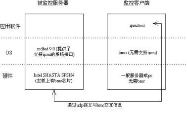
IPMI
https://www.ibm.com/developerworks/cn/linux/l-ipmi/index.html
IPMI通常需要BMC的支持,但是现今一般的主板包含BMC芯片
两种方式与bmc进行通信

- over kernel

- over lan
IPMI over lan,可以通过lan接口传输bmc消息,即每个主机都可以设置bmc中ipmi地址(不会列在ip addr中, 因为其是在bmc芯片中的,但是可以被其他主机arp)
客户端(控制端)可以不需要有bmc芯片,只需要有ipmitool程序就可,相应的需要在客户端配置路由(一般是直接配置一个被控制端ipmi网段的随机ip地址就行,会自动添加路由),总之需要让arp 被控制端ipmi地址的时候通过正确的路由到达被控制端服务器
- 由上可知,在客户端可以不设置ip地址,只要有正确的路由就行,但实验结果不行,猜测是数据返回时的问题?
- 注意
- 有些主板只有第一个网卡与BMC相连,所以要确保客户端路由可以与被控制端第一个网卡相连的网络接口相连
- 有些主板需要在bios中设置开启IPMI OVER lan
- 一般主机都会有个管理网口,默认设置为只能该管理口才能接受bmc信号(dedicate模式),需要连接该接口,使用ipmi地址登录web控制端,或者在主板启动时设置,修改bmc为share模式才可使得其他网口也可接受bmc信号,或者修改为failover模式,管理接口未被占用时才允许其他网口接受信号。
- dell的bmc控制器,叫做idrac,开启启动后按F10进入管理界面,idrac中设置ip over lan后使用的协议为lanplus
- lan和lanplus是传输的协议,下层协议都是udp,上层协议lan使用rmcp协议传输而lanplus使用rmcp+协议传输
# enable ipmimodprobe ipmi_simodprobe ipmi_devintfecho ipmi_si >> /etc/modprobeecho ipmi_devintf >> /etc/modprobeipmitool -I open channel info 1 // channel 1 type, normally is 802.3 LAN# server bmc settingipmitool lan set 1 ipsrc staticipmitool lan set 1 ipaddr 192.168.100.2ipmitool lan set 1 netmask 255.255.255.0ipmitool lan set 1 defgw ipaddr 192.168.100.254ipmitool lan set 1 defgw macaddr 00:0e:0c:aa:8e:13ipmitool lan set 1 arp respond onipmitool lan set 1 auth ADMIN MD5ipmitool lan set 1 access onipmitool lan print 1# server user settingipmitool user list 1ipmitool user set name 2 adminipmitool user set password 2ipmitool channel setaccess 1 2 link=on ipmi=on callin=on privilege=4ipmitool channel getaccess 1ipmitool user enable 2ipmitool channel --helpPossible privilege levels are:1 Callback level2 User level3 Operator level4 Administrator level5 OEM Proprietary level15 No access# client control# over lanset correct routeipmitool -I lan -H 192.168.100.3 -U admin -P admin power reset/on/off# over kernel(local system call)ipmitool -I open lan print 1
BitTorrent
.torrent
通常包含tracker信息,tracker就是公网服务器,使用同一文件下载的用户信息会被上传到服务器并被告知给其他客户
也可以不包含tracker,这样会通过DHT网络获取同一时间内在下载的用户
磁力链接
.torrent文件中的info block(不包含tracker信息?)的hash码,bt软件通过该链接下载时会通过DHT网络获取该磁力链所对应的info信息,之后再通过DHT网络获取其他在线用户

若有收获,就点个赞吧
0 人点赞
