Ch1: Computer Abstractions and Technology
考古题
1. Performance and CPU Frequency
Power Trends
Power = Capacitive load Voltage(电压)^2 Frequency(频率)
BUT
the power wll
- we cannot reduce voltage further
- we cannot remove more heat
- how can we improve performance?

- how can measure execution time?
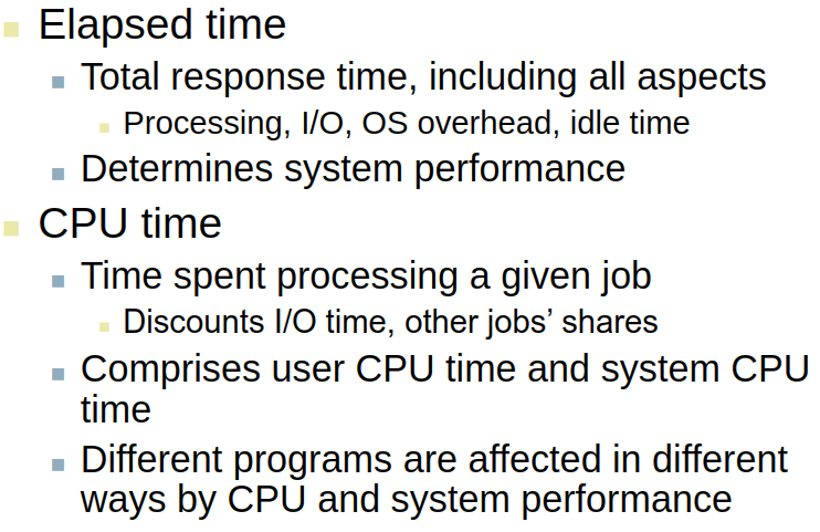
- CPU Time

- Performance improved by
- Reduce number of clock cycles
- increase clock rate
- hardware designer must often trade off clock rate against cycle count
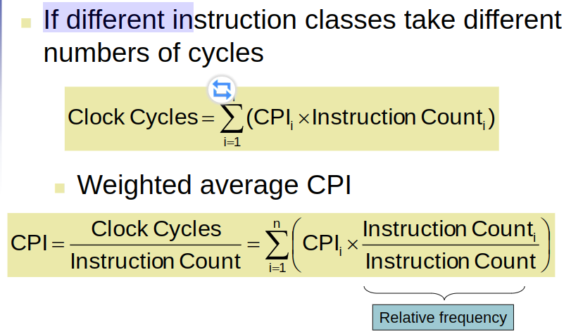
- Different numbers of cycles for different instructions

- Multiplication takes more time than addition
- Floating point operations take longer than integer ones
- Access memory takes more time than access registers
- important point: changing the cycle time often changes the number of cycles required for various instructions(more later)
2. Performance and CPI
- Instruction Count and CPI


- Instruction Count for a program
- determined by program, ISA and compiler
- Average cycles per instruction
- Determined by CPU hardware
- if different instructions have different CPI
- Average CPI affected by instruction mix
3. Performance Summary

Performance depends on
Does not account for
- differences in ISAs between computers
- differences in complexity between instructions

- CPI varies between programs on a given CPU
Ch2: Instructions:Language of the Computer
考古题
1. Design Principle
- Simplicity favours regularity
- Small is faster
- Make the common case fast
- Good Design demands good compromises
2. Procedure call
3. Instruction Format and Addressing Mode
4. Synchronization and Linkage
Instruction set:
- the repertoire of the instructions of a computer
- Different computers have different instruction sets(But with many aspects in common)
- Early computers had very simple Instruction sets(and simplified implementation)
- Many modern computers also have simple instruction sets
MIPS Instruction Set
MIPS Instructions
Arithmetic Operations
Add and subtract three operands
- Two sources and one destination
add a,b,c # a gets b+c
- Two sources and one destination
All arithmetic operations have this form
- Design Principle 1: Simplicity favours regularity
- regularity makes implementation simpler
- Simplicity enables higher performance at low cost
C Code
f = (g + h) - (i + j);
Compiled MIPS Code
add t0, g, h # temp t0 = g + hadd t1, i, j # temp t1 = i + jsub f ,t0,t1 # f = t0 - t1
Register Operands
- Arithmetic Operation use register Operands
- MIPS has a 32 * 32-bit register file
- Use for frequently accessed data
- Numbered 0 to 31
- 32-bit data called a “word”
- Assembler names
- $t0, $t1, …, $t9 for temporary values
- $s0,$s1, …, $s7 for saved variables
- Design Principle 2: Small is faster
C Code
f = (g + h) - (i + j);
Compiled MIPS Code
add $t0, $s1, $s2add $t1, $s3, $s4sub $s0, $t0, $t1
Memory Operands
- Main memory used for composite data
- Arrays, Structures, dynamic data
- To apple arithmetic operations
- load values from memory into registers(lw $t0, ,,,)
- store values from register to memory(sw $t0,…)
- Memory is byte addressed
- each address identifies an 8-bit byte
- Words are aligned in memory
- Address must be multiple of 4
- MIPS is Big Endian
- Most-significant byte at least address of a word
- Little Endian: Least-significant byte at least address
例如有数据0x01234567 (注意:左边是高字节,右边是低字节)
Big Endian:
存放的地址依次为:0x0001 0x0002 0x0003 0x0004
对应的数据依次为:0x01 0x23 0x45 0x67
示意图如下: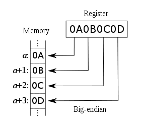
Little Endian:
存放的地址依次为:0x0001 0x0002 0x0003 0x0004
对应的数据依次为:0x67 0x45 0x23 0x01
示意图如下: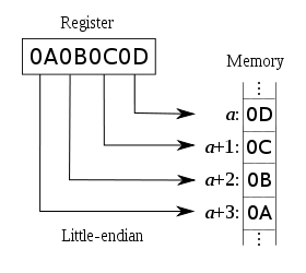
Registers vs. Memory
- registers are faster to access than memory
- Operating on memory data requires loads and stores
- More instruction to be executed
Compiler must use registers for variables as much as possible
Constant data specified in an instruction(addi $s3, $s3, 4)
- No subtract immediate instruction(addi $s2, $s1, -1)
- just use a negative constant
- Design Principle 3: Make the common case fast
- Small constants are common
- Immediate operand avoids a load instruction
Constant Zero
- MIPS register 0($zero) is the constant 0
- cannot be overwritten
- Useful for common operations
- E.g., move between registers(add $t2, $s1, $zero)
Unsigned Binary Integers
2s-Complement Signed Integers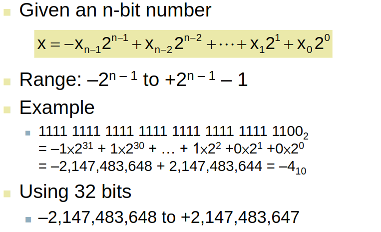
- Bit 31 is sign bit
- 1 for negative numbers
- 0 for non-negative numbers
- Signed Negation
- Complement and add 1

Sign Extension
(在不同的 bit number 中做一个转换,比如一个负数可以用 4-bit 来表示,也可以用 8-bit 来表示,需要中间去做一个转换才行)
- Representing a number using more bits(Preserve the numeric value)
- In MIPS instruction set
- addi: extend immediate value
- lb, lh: extend loaded byte/halfword
- beq, bne: extend the displacement
- Replicate the sign bit to the left
- unsigned values: extend with 0s
Examples: 8-bit to 16-bit
instructions are encoded in binary(Called machine code)
- MIPS Instructions
- Encoded as 32-bit instruction words
- Small number of formats encoding operation code(opcode), register numbers,…
- Regularity
- Register numbers
Instruction fields
- op: operation code(opcode)
- rs: first source register number
- rt: second source register number
- rd: destination register number
- shamt: shift amount (00000 for now)
- funct: function code(extends opcode)
For Example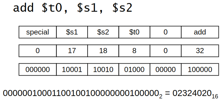
Hexadecimal(十六进制)
- base 16
- compact representation of bit strings
- 4 bits per hex digit

- Example: eca8 6420
- 1110 1100 1010 1000 0110 0100 0010 0000
MIPS I-format instructions
| op | rs | rt | constant or address |
|---|---|---|---|
| 6 bits | 5 bits | 5 bits | 16 bits |
- Immediate arithmetic and load/store instructions
- Constant: -2^15to +2^15 - 1
- Design Principle 4: Good Design demands good compromises
- different formats complicate decoding, but allow 32-bit instructions uniformly
- keep formats as similar as possible
Logical Operations
Instructions for bitwise manipulation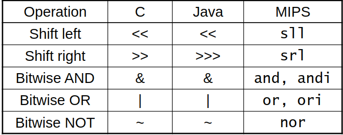
and/or $t0, $t1, $t2
NOT Operations
MIPS has NOR 3-operand instruction
a NOR b == NOT( a OR b )
nor $t0, $t1, $zero
Shift Operations
| op | rs | rt | rd | shamt | funct | | —- | —- | —- | —- | —- | —- | | 6 bits | 5 bits | 5 bits | 5 bits | 5 bits | 6 bits |
shamt: how many positions to shift
- shift left logical
- shift left and fill with 0 bits
- sll by i bits multiples by 2^i
- shift right logical
- shift right and fill with 0 bits
- srl by i bits divides by 2^i (unsigned only)
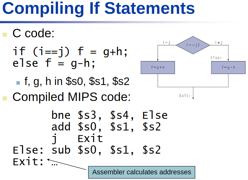
Conditional Operations
branch to a labeled instruction if a condition is true( otherwise, continue sequentially)
- beq rs, rt, L1
- if (rs == rt) branch to instruction labeled L1;
- bne rs, rt, L1
- if (rs != rt) branch to instruction labeled L1;
- j L1
- unconditional jump to instruction labeled L1;

Basic Blocks
- A basic blocks is a sequence of instructions with
- No embedded branches(except at end)
- No branch targets(except at beginning)
- A compiler identifies basic blocks for optimization
- An advanced processor can accelerate execution of basic blocks
More Conditional Operations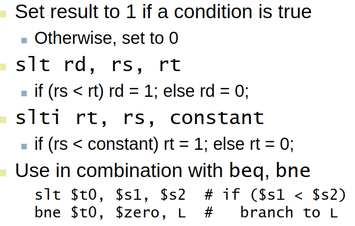
Branch Instruction Design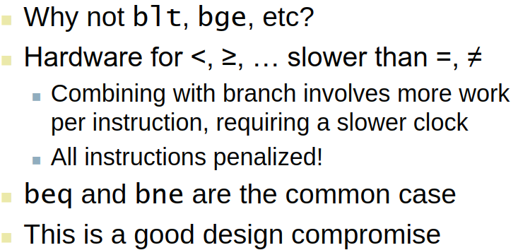 **
**

Procedure Calling
- Steps required
ch3: Arithmetic for Computers
考古题
1. Addition Overflow
2. Multiplier hardware
3. Arithmetic Division
4. Floating point operation
5. Carry lookahead adder
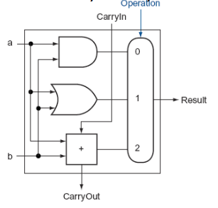
ALU
Basic Arithmetic Logic Unit
One-bit ALU that performs AND, OR, and addition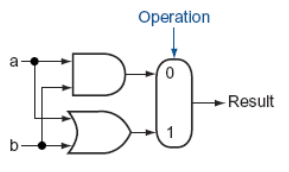
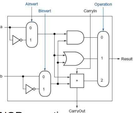
Enhanced Arithmetic Logic Unit
ALU that have NAND/NOR operation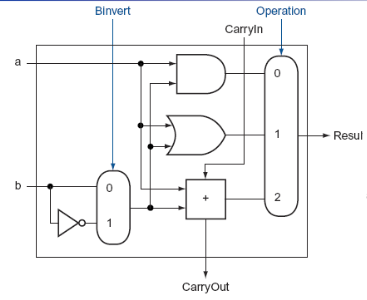
32-bit ALU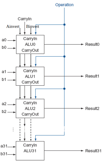
One-bit ALUs with Set Less Than
- Set less than instruction requires a subtraction and then sets all but the least significant bit to 0, with the lsb set to 1 if a < b
- Less signal line
- lsb(least significant bit) - signed bit
- all but the lsb - 0
Arithmetic for Computers
- Operations on integers
- addition and subtraction
- multiplication and division
- dealing with overflow
- Floating-point real numbers
- Representation and operations
Operations on integers
addition and subtraction
Integer Addition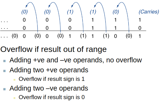
Integer Subtraction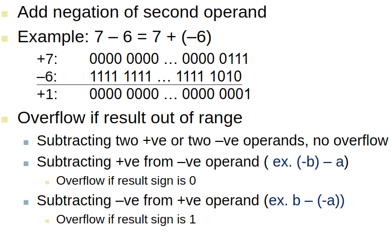
Dealing with Overflow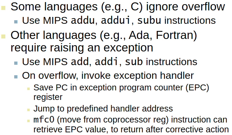 **
**
Overflow Detection for Signed & Unsigned Addition
Signed addition
addu $t0, $t1, $t2xor $t3, $t1, $t2(异或)slt $t3, $t3, $zerobne $t3, $zero, No_overflowxor $t3, $t0, $t1slt $t3, $t3, $zerobne $t3, $zero, Overflow
Unsigned addition
addu $t0, $t1, $t2nor $t3, $t1, $zerosltu $t3, $t3, $t2bne $t3, $zero, Overflow
Multiplication
ch4:The Processor
Introduction
- CPU performance factors
- instruction count
- Determined by ISA and compiler
- CPI and Cycle time
- Determined by CPU hardware
- instruction count
- We will examine two MIPS implementations
- a simplified version
- a more realistic pipelined version
Simple subset, shows most aspects
Use ALU to calculate
- Arithmetic result
- Memory address for load/store
- Branch target address
- Access data memory for load/store
- PC <- target address or PC + 4
Control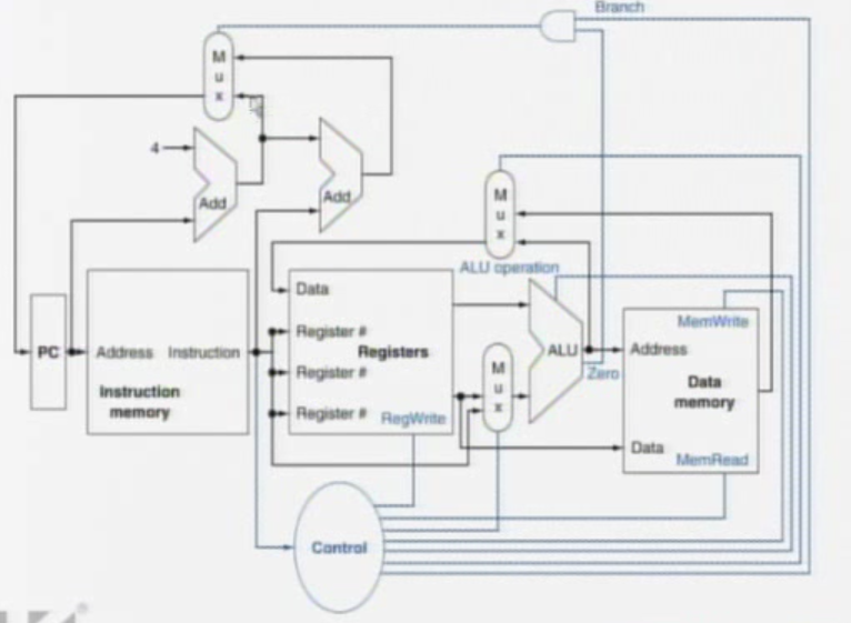
Logic Design Basics
- information encoded in
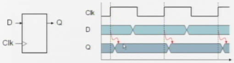
Sequential Elements
Register: stores data in a circuit
- Uses a clock signal to determine when to update the stored value
- Edge-triggered: update when Clk changes from 0 to 1
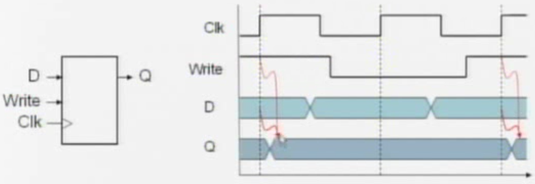
Register with write control
- only updates on clock edge when write control input is 1
- used when stored value is required later
Clocking Methodology
combinational logic transforms data during clock cycles
- between clock edges
- input from state elements, output to state element
- longest delay determines clock period
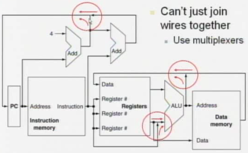
Building a Datapath
Performance Issues of Single Cycle Design
- longest delay determines clock period
- critical path: load instruction
- Instruction memory -> register file -> ALU -> data memory -> register file
- Not feasible to vary period for different instructions
- Violates design principle
- Making the common case fast
- We will improve performance by pipelining
MIPS Pipeline
five stages, one step per stage
- IF: instruction fetch from memory
- ID: instruction decode & register read
- EX: Execute operation or calculate address
- MEM: Access memory operand
- WB: Write result back to register
Hazards
Situations that prevent starting the next instruction in the next cycle

若有收获,就点个赞吧
0 人点赞
