Revision history
| Date | Version | Content |
|---|---|---|
| 2020-03-23 | V1.0 | The first version of the instructions |
Disclaimer
Welcome! Thank you for choosing Makeblock!
Before installing and operating mCreate for the first time, read all the accompanying written materials carefully for a better experience with it. Makeblock Co., Ltd. (Shenzhen) will not be liable for any loss caused by failure to operate mCreate as instructed and required in this Instruction or improper operation due to misunderstanding, except for such loss due to improper installation or operation by Makeblock professional maintenance personnel.
Makeblock Co., Ltd. (Shenzhen) has taken much care to ensure the accuracy of this Instruction, but cannot guarantee it is completely free from errors or omissions.
Makeblock Co., Ltd. (Shenzhen) is committed to continuously improving the products and services, and therefore reserves the right to change any product or software program described in the Instruction and the contents of the Instruction at any time without prior notice.
This Instruction is intended to help you use the product properly and does not include any description of the product hardware and software configuration. For product configuration, refer to the relevant contract (if any) and packing list, or consult your distributor. Pictures in the Instruction are for reference only and the actual product may vary.
Protected by copyright laws and regulations, the Instruction shall not be reproduced or transcribed in any way, or be transmitted on any wired or wireless network in any manner, or be translated into any language without the prior written authorization of Makeblock Co., Ltd. (Shenzhen).
Video tutorials
We provide video tutorials to help you quickly get started with mCreate. For more features, please visit: https://www.makeblock.com/mcreate-video
Safety First (Important)
The nozzle and the build plate of mCreate have warning labels on them. These labels indicate any potential hazard that may cause injury to you or others, or damage to the product or property. 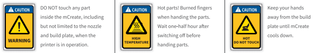
General safety
Read and get familiar with all safety protocols and procedures before operating mCreate. You shall strictly follow all safety precautions and ensure that the mCreate is properly assembled and in working order.
Please observe the following operating principles:
- Be sure to check mCreate for damage every time before use. DO NOT operate any damaged or defective mCreate in any way.
- Please keep the workspace clean, flat and stable. Any shake during operation may lead to a lower printing accuracy or even layer shifting.
- Operate mCreate in a well-ventilated area.
- Assemble mCreate as instructed in this Instruction. DO NOT disassemble or change the printer’s structure in any other way; and DO NOT modify or decompile the operating system of mCreate on your own.
- DO NOT leave mCreate unattended for a long time when the printer is in operation.
Children under 12 years old shall use the printer under adult supervision.
Electrical safety
Read the following warnings and suggestions carefully:
ONLY use mCreate with the power cables supplied by Makeblock!
- Make sure mCreate is grounded when you use it. Avoid placing the printer in a humid environment. Improper grounding or operating the mCreate in a humid environment will increase the risk of currents leakage.
- DO NOT use mCreate during a thunderstorm.
- Turn off and unplug mCreate when it is not intended to be used for a period of time.
Operational Safety
Read the following warnings and suggestions carefully:
- Keep your hands away from any moving parts when mCreate is in operation.
- When using mCreate, DO NOT wear a scarf, gloves,jewelry or other things that are easily sucked into the printer.
- Always turn off and unplug mCreate and make sure it cools down before you change any component or part.
Warnings
Read the following warnings and suggestions carefully:
- DO NOT touch the nozzle or build plate when mCreate is printing.
- DO NOT touch the nozzle or build plate immediately after a 3D print job is done because they may still be hot. View the current temperature of the nozzle and build plate shown on the touch screen. Always let them cool down completely before doing anything to them.
- Use the 3D printing materials recommended by Make block. Improper 3D printing materials may clog the nozzle.
- Unload the filament and turn off mCreate before removing the 3D printing nozzle. Be careful when removing the nozzle because it may still be hot.
- When mCreate is laser engraving a project, wear the goggles to avoid eye damage that may be caused by looking directly at the laser dot.
- mCreate may generate a small amount of smoke or smell during laser engraving. We recommend you operate the printer in a well-ventilated area.
Preparation
List of items
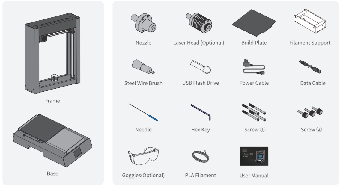
Components of mCreate
Assemble mCreate
See assembly videos at: https://www.makeblock.com/mcreate-video
Replace the toolhead
- Turn off mCreate.
Make sure mCreate is powered off and the power cable is disconnected.
- Remove the tool head.
2.1 Press down.
2.2 Take the tool head out.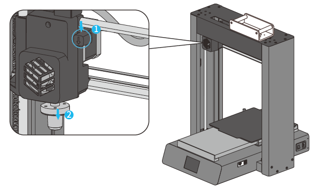
- Install another tool head.
3.1 Press down and hold.
3.2 When installing a tool head, make sure its flat side faces to the left.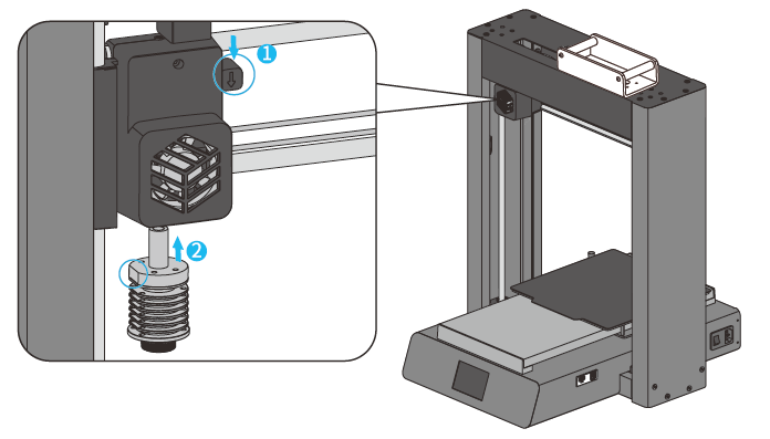
Download and install software
Download Ultimaker Cura
Ultimaker Cura is the 3D printing software designed by Ultimaker for slicing. It provides almost all the features necessary for 3D printing, aiming to be highly integrated and easy to use. Download Cura at: Download Cura at: https://ultimaker.com/software/ultimaker-cura
Install Ultimaker Cura
- Run the installer
Run the Cura installer after downloading it.
- Choose the destination location
Choose where to install your Cura. Click Next to continue.
Please remember the destination location in case you may need it when installing plugins later.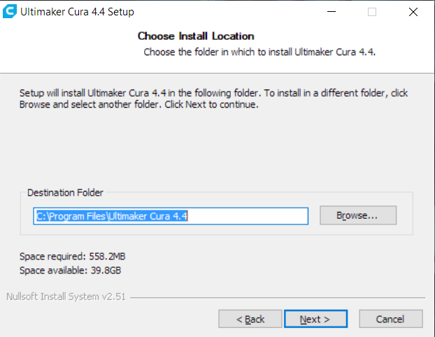
- Choose components
Decide whether to install additional software or choose to open a specific format with Cura by default. It’s recommended not to change the setting unless necessary. Click Install to get Cura installed.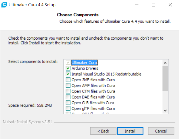
- Finish
After installation is complete, remember to uncheck Run Ultimaker Cura 4.4 (R). Don’t run it until the installation of the plugin is completed. Click Finish to exit the installer.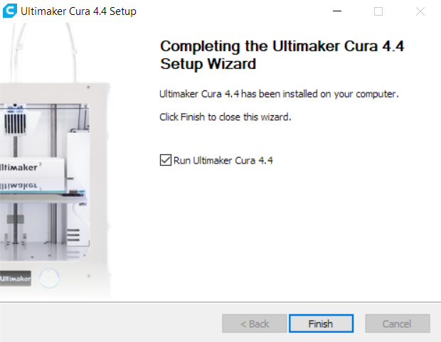
Download Cura plugin
mCreate comes with a custom slicing plugin for 3D printing. Installing this plugin can save you hassle by automatically importing mCreate related parameters and the best print settings into Cura. You don’t need to define the settings by yourself, but you still get the best print. Download plugin at: https://www.makeblock.com/mcreate-2#software
Install Cura plugin
Make sure you already installed the software Ultimaker Cura on your computer before installing the plugin. Please make sure the plugin is installed in the Cura file path.
Follow the steps to check the Cura file path: right-click the Cura icon on the desktop, click Properties, and you will see the Cura file path. 
Set up Ultimaker Cura
- Add printer
Click the printer tab at the upper left corner, and you’ll see a panel, click Add printer.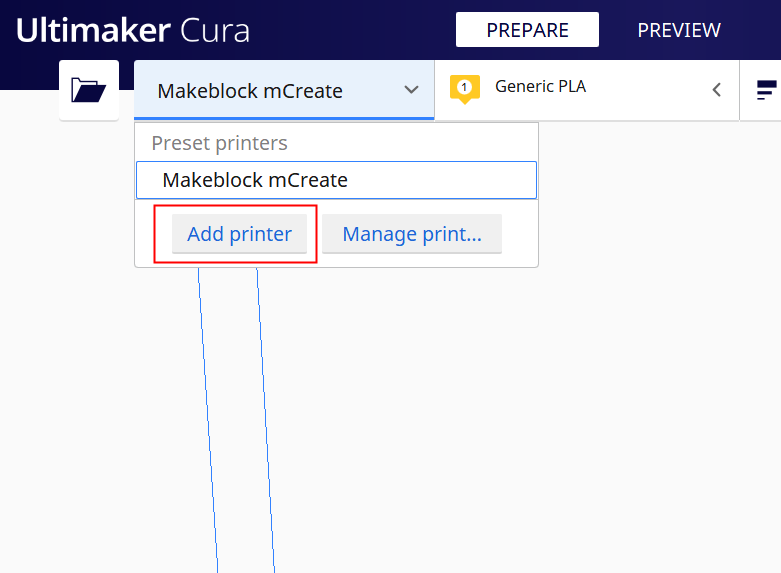
<br />Click **Add printer** Printer list<br />
- Find mCreate
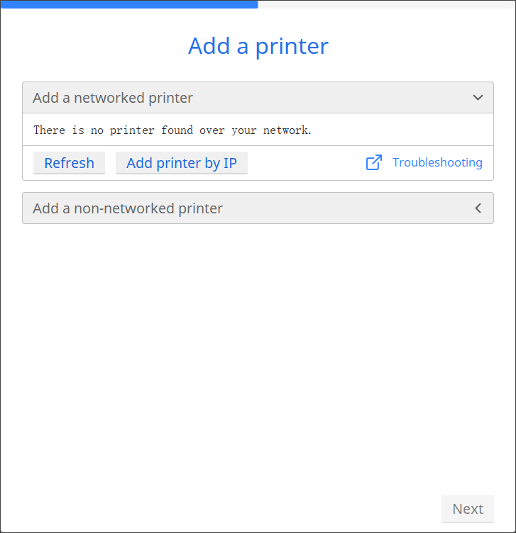
Click Add a non-networked printer, find Makeblock, and select Makeblock mCreate. Then click Next to import mCreate-related parameters into Cura. If Makeblock is not on the list, it means the plugin installation failed. Learn more about >Download and Install Software. 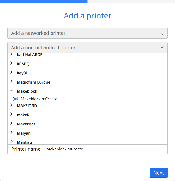
- Finish
When you see Makeblock mCreate appearing on the printer tab, it means the 3D printer is successfully added.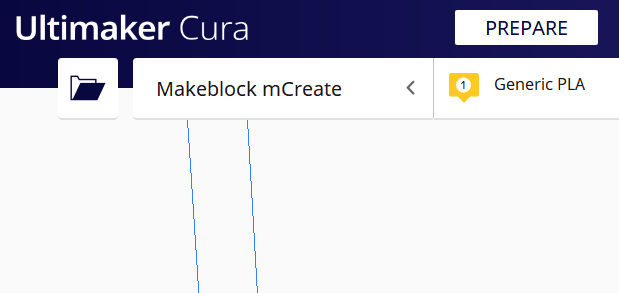
Download Laserbox for mCreate
Laserbox for mCreate is the laser engraving software designed by Makeblock for mCreate. The software offers in-built parameter settings available for engraving on commonly-used materials. It also provides essential design tools that you can depend on to create different shapes and add filters to your design. Download Laserbox for mCreate at:
https://www.makeblock.com/mcreate-2#software
Install Laserbox for mCreate
- Run installer
Run the Laserbox for mCreate installer you just downloaded.
- Choose destination location
Choose the folder into which you’re going to install Laserbox for mCreate. Click Next to continue.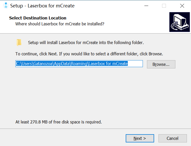
- Select additional tasks
Follow the on-screen prompts to select any of the additional tasks you want to perform, including adding a folder to the Start menu or creating a desktop shortcut. In the interface below, check through all the settings you selected in the previous steps. Click Install to execute the installation.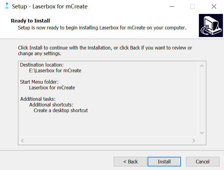
- Finish
After the installation is complete, click Finish to exit the installer.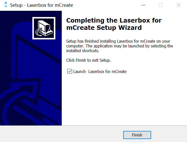
Interface overview
3D printing interface
mCreate has 2 modes: 3D Printing and Laser Engraving. When mCreate has a 3D printing nozzle installed, you will see an interface like this: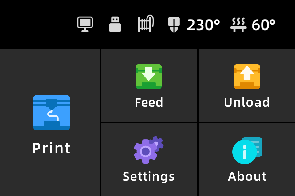
The interface includes:
- Print Display the file included in the USB flash drive and print it.
- Feed Heat up the nozzle and load the filament into the nozzle.
- Unload Heat up the nozzle and unload the filament from the nozzle.
- Settings Customize mCreate settings to fit your own purposes.
About Show device information and firmware updates.
Display status
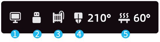
Already connected to computer
- USB flash drive already inserted
- Filament already inserted
- Nozzle temperature
-
Laser engraving interface
mCreate has 2 modes: 3D Printing and Laser Engraving. When mCreate has a laser head installed, you will see an interface like this:
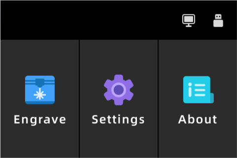
When mCreate has a laser head installed, you will see an interface like this: Engrave Display the file included in the USB flash drive and engrave it.
- Settings Customize mCreate settings to fit your own purposes.
About Show device information and firmware updates.
Display status
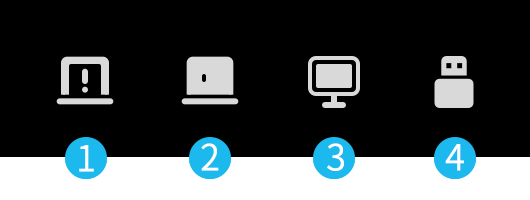
Enclosure opened (Only mCreate 2.0 support enclosure status display)
- Enclosure closed (Only mCreate 2.0 support enclosure status display)
- Already connected to computer
USB flash drive already inserted
Features
Load the filament
Feed
Tap Feed on the touch screen. Then the nozzle will start heating.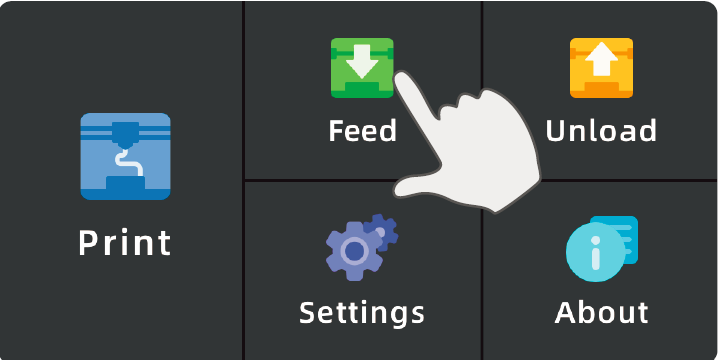
- Place the filament
When the nozzle is fully heated, the touch screen will prompt you to load the filament. Trim the end of the filament before inserting it through the hole on the Filament Support.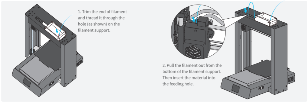
- Complete feeding
Tap Complete when you see the filament coming out of the nozzle to complete the feeding procedure. 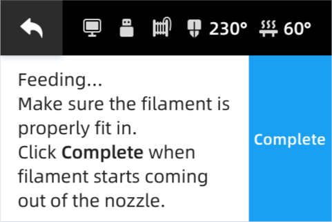
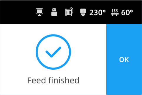<br />Feeding... Feed finished
Unload filament
- Unload
Tap Unload on the touch screen. Wait for the nozzle to finish heating up.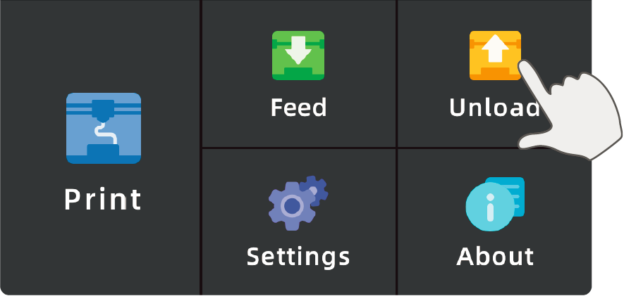
- Complete unloading
mCreate will automatically unload the filament. When the touch screen displays Unload Finished, you can pull the filament out of the feeder to finish unloading.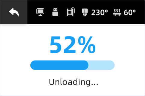
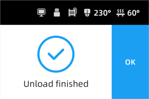<br />Unloading Unload finished<br />
3D Printing
- Process a 3D file
1.1 Run Ultimaker Cura. Click the File icon at the top left corner or drag a 3D file into Cura to import model.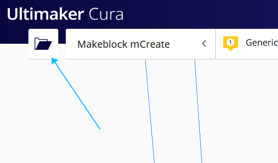
1.2 Click Slice at the bottom right corner to start slicing.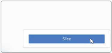
1.3 Click Save as makeblock format to save your file.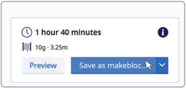
1.4 Copy the saved file to the USB flash drive.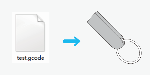
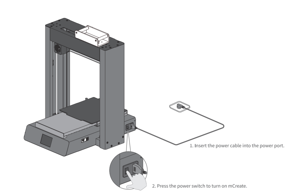
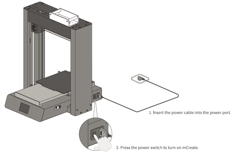
- Plug in and power on
- Start printing
3.1 Insert the USB flash drive into the USB Drive Port of mCreate.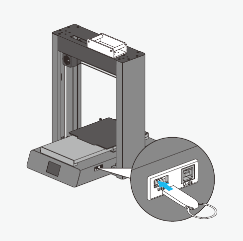
3.2 Select the file. Tap Print on the 3D printing home screen, and select the file you want to print. Tap the arrows on the right-hand side to scroll the file list.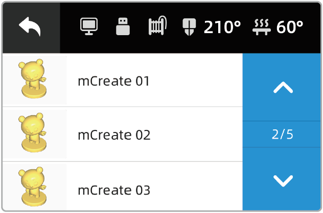
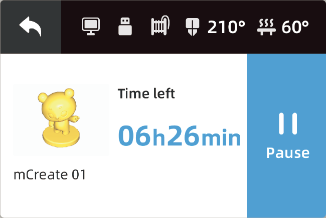
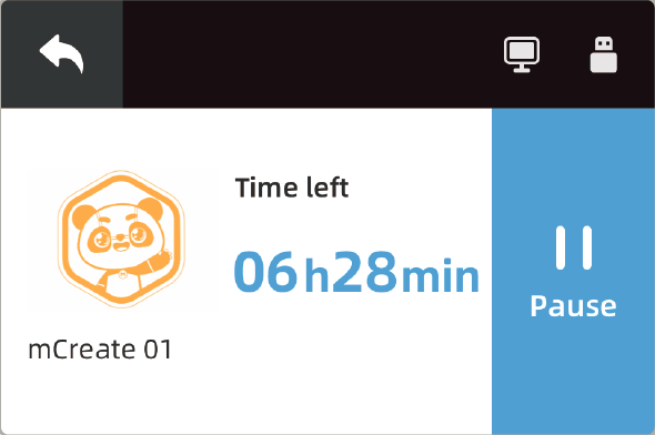
3.3 Start printing. When you select a file, its file name, model preview and estimated print time will be displayed on the touch screen.Tap Start to start printing.
3.4 Preparing for printing.Before printing, mCreate has to be prepared by:
- Resetting the nozzle;
Heating the nozzle and the build plate to the target temperature. You can view the current temperature in the status bar on the touch screen.
3.5 During printing. You can pause or cancel the task during the printing process:
- Pause – Tap Pause to stop the print task. The nozzle and build plate will remain hot so that you can resume the print task any time.
- Cancel – Tap the Back Arrow at the top left corner to cancel the current task.
- Print finished
Before taking out your print, check the temperature of the build plate. When the build plate cools down, take out both the print and the build plate. Gently twist the build plate to get your print off it.
Laser engraving
- Process a engraving file
1.1 Run Laserbox for mCreate, go to Menu -> Improt or directly drag a picture to import the file.
1.2 On the right-hand tool bar, you can define the parameters or select a filter effect.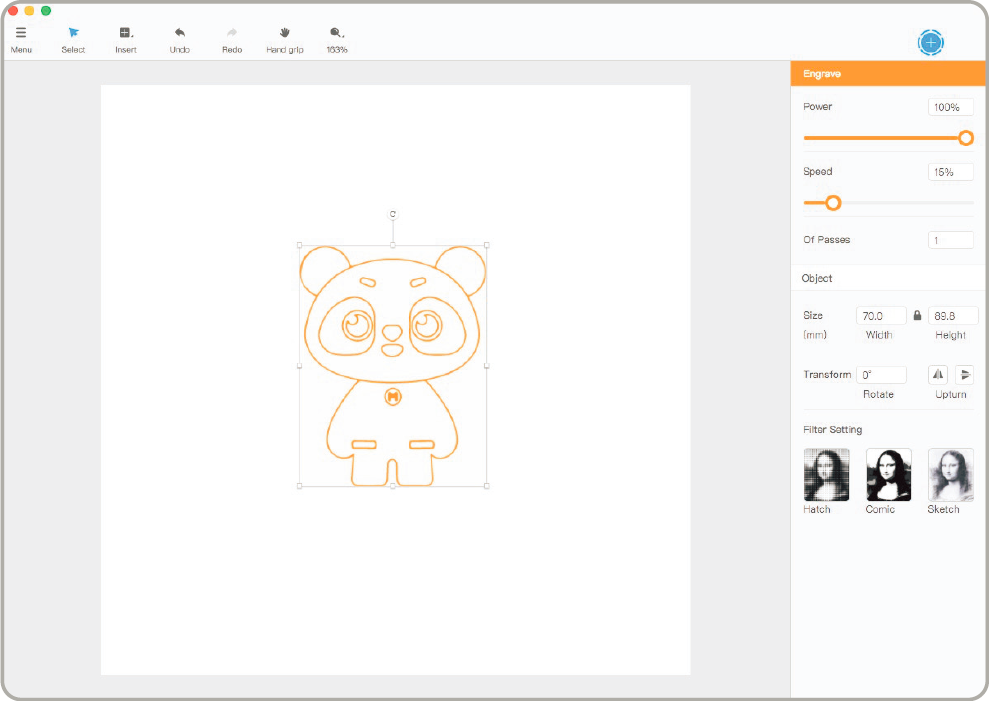
1.3 Go to Menu->Export, save your file with the suffix Ibx and copy it to the USB flash drive.
- Connect the power cable and turn on power
- Start engraving
3.1 Insert the USB flash drive into the USB drive port.
3.2 Select the file. On the operation interface, tap Engrave to select the file you want to engrave. Tap the arrows on the right-hand side to scroll the file list.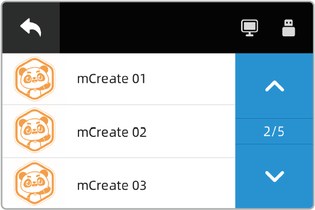
3.3 Focusing. After the file is selected, the interface will display many information, including file name, file to be engraved and estimated engrave time. Before engraving, you should put the item you want to engrave on the central area of the build plate and tap Focus.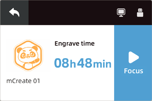
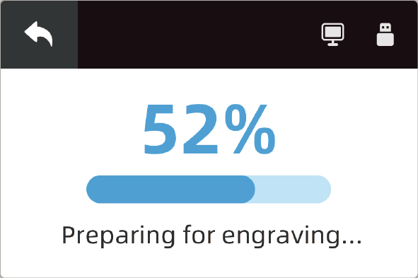
3.4 Preparing for engraving. Before engraving, mCreate has to be prepared by:
- Resetting the laser head
- Automatically focusing
3.5 Position and Bound. With these two features, you can define where to engrave on the item:
- Arrow keys – Move the laser head.
- Position – Locate the laser head and use the current position as the initial point where bounding begins.
- Bound – Indicate the area to be engraved for the current file.
After defining the position and area where you want to engrave, tap Start to begin the engraving task. 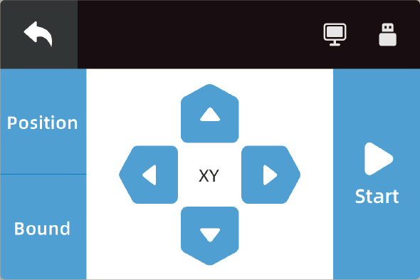
3.6 Engraving. You can pause or cancel the task during the engraving process:
- Pause – Tap Pause to stop the print task. The nozzle and build plate will remain hot so that you can resume the print task any time.
- Cancel – Tap the Back Arrow at the top left corner to cancel the current task.
- Engrave finished
mCreate will automatically reset the position of laser head and build plate, keep your hands away from any moving parts. Take the material after mCreate finished resetting.
Buzzer
What can it do?
mCreate comes with an built-in buzzer that can give a notification sound when a task or command is complete.
How to use it?
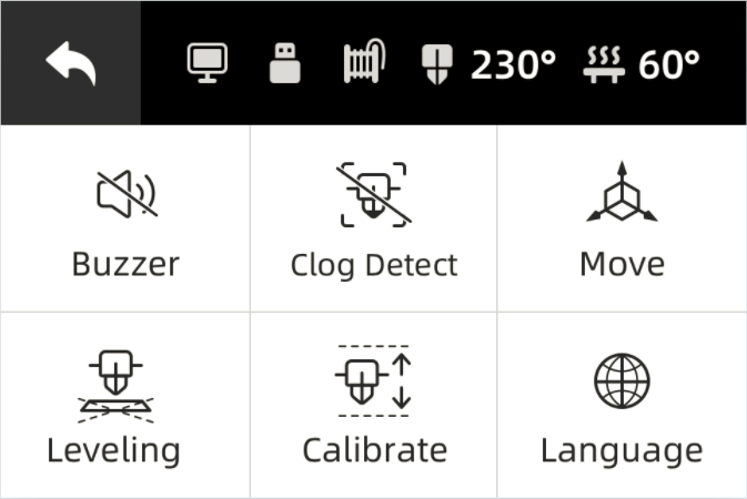
In Settings, you can see the buzzer’s on/off status. The buzzer is turned on by default, but you can still tap Buzzer to turn it off/on. 
<br />Buzzer on Buzzer off<br />
Clog detection
What can it do?
During the printing process, mCreate may detect the filament not moving (not coming out of the nozzle) for a long time, which we call Clogging. In this situation, mCreate automatically cancels the task in order to prevent damage incurred.
Clogging refers to a situation where filament fails to be extruded out of the nozzle smoothly. There’re 3 types of clogging depending on where clogging occurs:
- Spool clogging (or as entanglement): The entanglement of filament on the spool leads to the failure of the spool to rotate properly. The filament fails to enter the feeder. A long time of entanglement causes thinner filament because it’s repetitively rubbed by the gear. As a result, the filament can’t enter the nozzle properly.
- Gear clogging: Filament gets clogged at the gear due to overheating or non-uniform filament. As a result, filament fails to be melted and extruded from the nozzle.
- Nozzle clogging: Filament fails to be extruded from the nozzle due to the wrong temperature setting or particles stuck in the nozzle.
Clogging is a potential issue for almost every FDM printer. If clogging happens, filament will fail to be extruded from the nozzle when the 3D printer continues working. A long time of heating over a specific piece of filament will carbonize it and damage the nozzle. It may even destroy the 3D printer when clogging gets serious. Learn how to unclog your mCreate at: https://www.makeblock.com/support/ps-mcreate
How to use it?
In Settings, you can check whether Clog Detect is turned on or off. Clog detect is turned on by defalut. But you can tap Clog detect to turn it off/on. 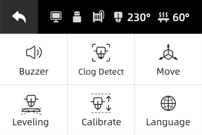
<br />Clog detect on Clog detect off<br />
Move
What can it do?
mCreate ‘s tool head or build plate moves in an X-Y-Z system. We use X coordinates to move the tool head left/right, Z coordinates to let it rise/fall. We use Y coordinates to move the build plate forward/backward.
How to use it?
In Settings, tap Move to enter the control panel.
“X axle: Tap “←” to move the tool head to the left; tap “→” to move the tool head to the right;”
“Y axle: Tap “↑” to move the build plate away from you; tap “↓” to move the build plate closer to you; “
“Z axle: Tap “↑” to lift the tool head; tap “↓” to bring down the tool head. “
Tap Reset to move the tool head to the leftmost on X axle and upmost on Z axle, the build plate to the utmost on Y axle. 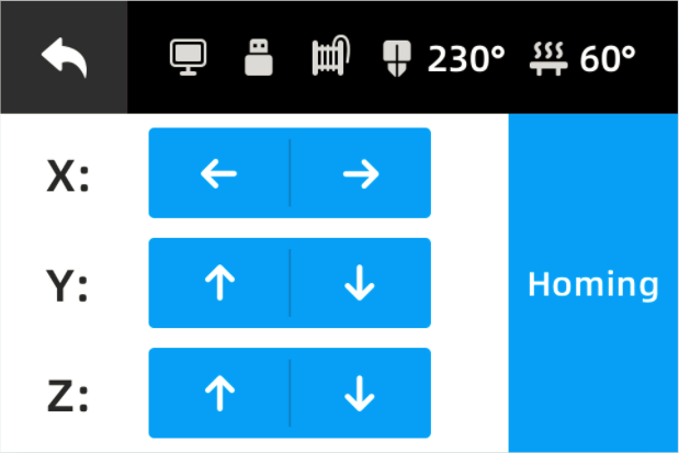
Leveling
What can it do?
Leveling refers to the process of adjusting the nozzle or the build plate to ensure the distance between them is appropriate and consistent. Doing this, you can make sure the first layers evenly adhere to the build plate. The traditional way to perform leveling is to level the build plate by adjusting the 4 screws below. However, mCreate depends on Genius smart leveling. With its built-in AI detection module, mCreate can automatically calculate the height of the build plate. Using this information, mCreate can adjust the height of the build plate to ensure a proper distance between the nozzle and the build plate, which helps with successful prints. With mCreate, precise leveling is just a button away. If filament fails to evenly adhere to the build plate when the first layer is printed, you should start the leveling procedure.
How to use it?
In Settings, tap Leveling to start the procedure. Before leveling, please make sure:
- Filament is already unloaded from the nozzle.
- The build plate is clean.
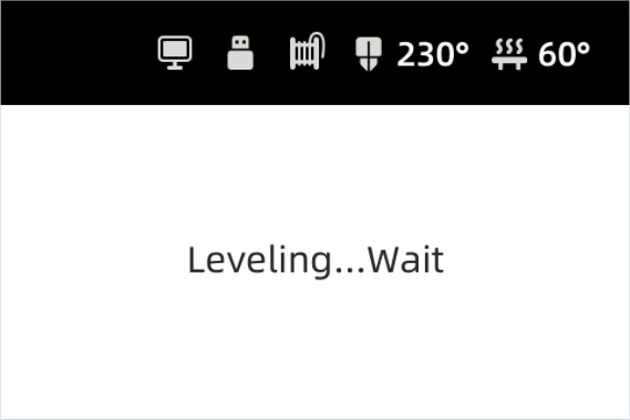<br />Tap Leveling in Settings Wait for leveling to finish<br />
Calibrate
What can it do?
Calibration refers to the process of adjusting the build plate or nozzle to ensure a proper distance between them when the first layers are being printed. 3D printing is a technique used to construct objects layer by layer. We rely on calibration to ensure a proper distance between the nozzle and the build plate so that the first layer printed firmly adheres to the build plate. This ensures the reliable adhesion of successive layers to the build plate, which is important for successful prints. If the nozzle is too far from the build plate, filament will fail to adhere to the build plate; if the nozzle is too close to the build plate, it may lead to insufficient filament extruded from the nozzle or scratches on the build plate. So you need to calibrate when these happen. 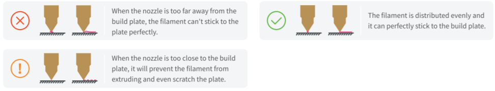
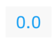
How to use it?
In Settings, tap Calibrate to enter the interface. The value displayed is the calibration value generated by auto-calibration. If the first layer failed to stick firmly to the build plate due to the nozzle being too far from the build plate, you need to decrease the value by 0.1; if filament extrusion failed or the build plate was scratched due to the nozzle being too close, you need to increase the value by 0.1.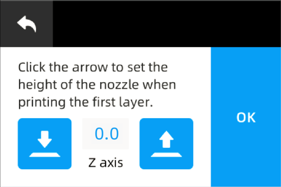
Language
What can it do?
mCreate touchn screen is multilingual. It offers users 2 language options. But the language pairs vary depending on regions. For the first time mCreate is started, language options will appear for users to select. If you need to reset the language afterwards, you can still change it in Settings.
How to use it?
In Settings, tap Language to set the language. mCreate offers 2 language options. Tap an option to switch to the language you want.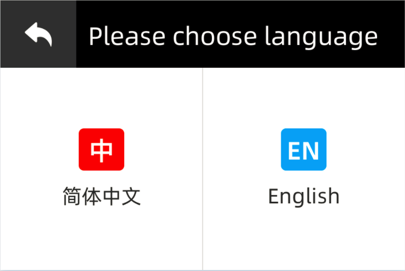
Focus setting
What can it do?
mCreate can automatically perform focusing. Put the object you’d like to engrave on the build plate, select the file, and tap Focus. The laser head will automatically go down to measure the object surface height. Then it will rise to the focus you already set. Adjusting the rising distance is a process of setting the focal length to refine your engravings.
How to use it?
In Settings, tap Focus Settings. Follow the on-screen prompt to put a piece of white paper on the center of the build plate. Tap OK to set the focal length. mCreate will engrave 5 numbers at five different focus. Observe the engravings, and select the number indicating the thinnest engraving to set the focal length.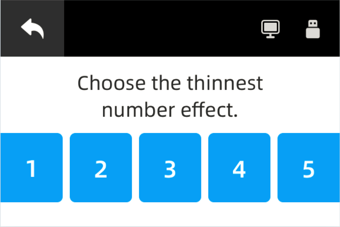
Device info
What can it offer?
mCreate allows users to view the device information so that you can quickly check the device’s operating status.
How to use it?
Tap About to see the device’s serial number, firmware version, boot time, printing time and engraving time.
Firmware updates
What can it offer?
mCreate supports firmware updates. New firmware versions usually have some bugs fixed and improve performance and reliability.
How to update?
- Get firmware ready
Download the latest firmware at Makeblock official website, or contact after-sales support to get one. Copy the firmware file to the root directory of the USB flash drive. Please note that you shouldn’t change the file name. Download the firmware at: https://www.makeblock.com/mcreate-2#software
- Insert USB flash drive
Insert the USB flash drive which has the firmware file into mCreate.
- Update firmware
Tap About. From there, and select Update. Wait for mCreate to complete the update procedure.
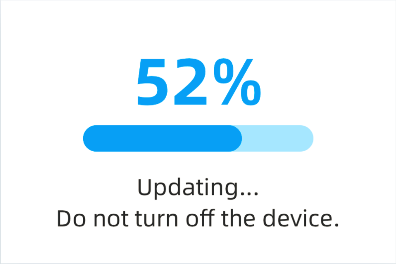<br />The About interface Updating...<br />
Factory reset
What can it do?
Factory reset will restore all the setup to its factory settings, including calibration, leveling, focusing, buzzer and clog detect.
How to use it?
Tap About, and select Reset. mCreate will redirect you to another interface where you need to confirm once again. Tap OK to let mCreate restore to its factory settings. Tap Cancel to go back to the About interface. 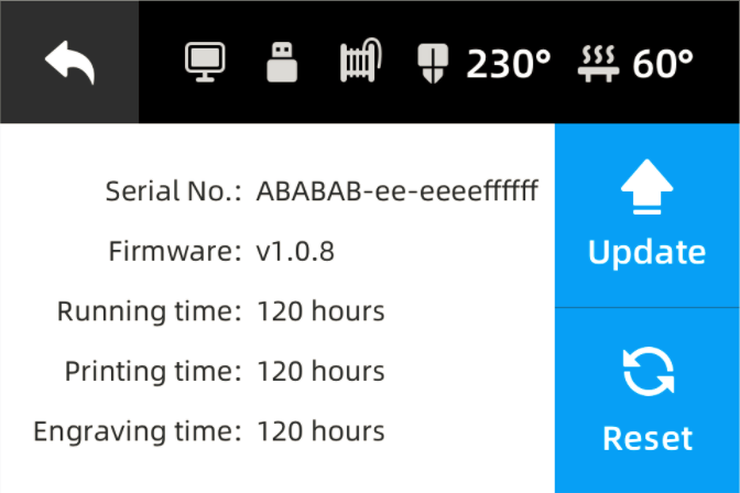
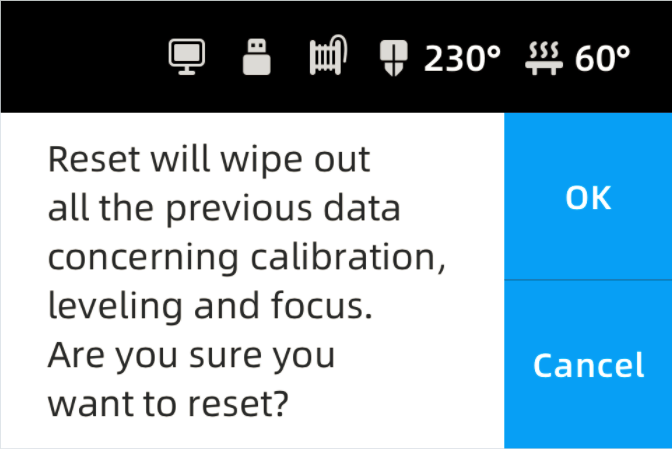
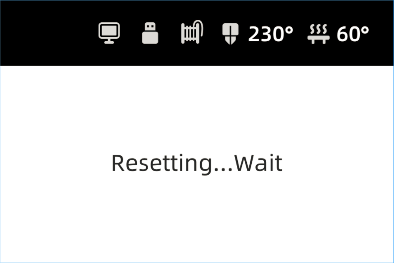<br /> The About interface Double confirm Resetting...<br />
Use Cura
3D print via computer
- Connect mCreate to your computer
Connect mCreate to your computer with the USB cable. When the connection is successful, a computer icon appears in the status bar on the touch screen.
- Model slicing
To import a model file, click the file icon at the upper left corner or directly drag the model file into Cura. Click Slice at the bottom right corner to start slicing.
- Start printing
When slicing is complete, the Slice button turns into Save as makeblock format. Click the arrow on the right side to show the drop-down list, and select print via USB on the list. If you click the button again, Cura will jump to the Print Monitor interface, and the touch screen displays “Working… “. The printer starts heating up and then prints the object automatically. During printing, you can view the nozzle temperature, build plate temperature, and task progress in Cura.
Interface overview
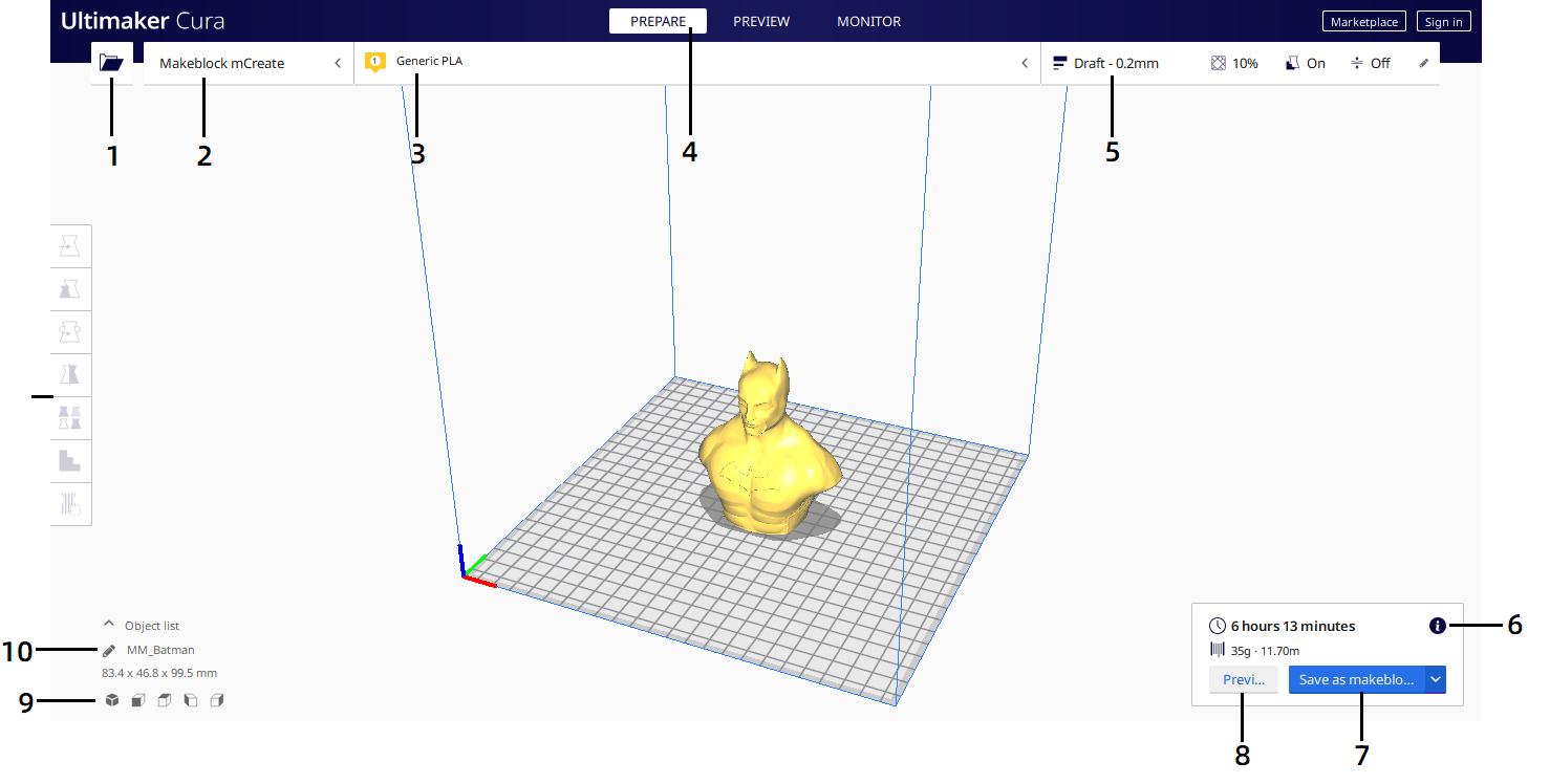
- Open file. Opens a 3D file.
- Printer selection panel. Displays the selected printer.
- Configuration panel. Contains the material and print core setup.
- Stages. The prepare. Preview and monitor stage. Each stage is arranged to efficiently go through each 3D printing step.
- Print settings panel. Contains all slice strategy parameters.
- Action panel. Contains an action button dependent on the current stage.
- Save as makeblock format. Save to removable disk or save to file.
- Preview. Proceeds to the next stage, the preview stage.
- Camera position tool. Easily positions the camera to default show default viewing angles.
- Model information. Contains the 3D model name and dimensions of all printable models on the build plate.
Adjustment tools Adjust the model before printing.
Stage 1 Prepare
The prepare stage is the first stage. The goal of this stage is to load and configure your 3D models for printing. More information on the individual configuration panels can be found in the Ultimaker Cura management section.
3D models loaded on the build plate are displayed solid, in the color corresponding to the material selected to print with. Models not fully within the printable area have a striped grey overlay.
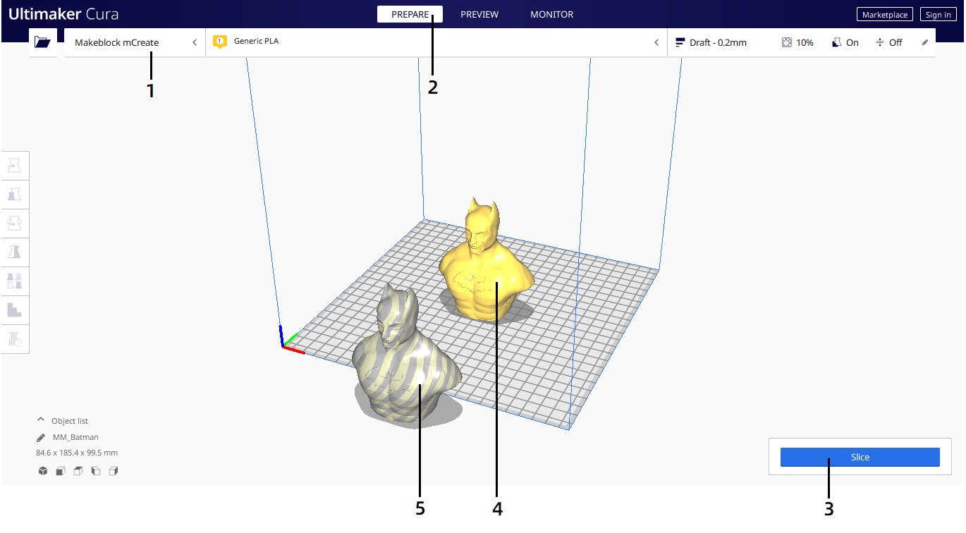
Printer. Contains the printer selection, configuration and print settings panel.
- Stage. The current stage is highlighted.
- Slice. Click to slice the model.
- Printable model. Displayed in the color corresponding to the material selected to print with.
Non-printable model. Due to parts being in non-printable areas.
Stage 2 Preview
The preview stage is the second stage. The goal of this stage is to preview and evaluate the 3D printing process. This stage can only preview the printed model when the model has been sliced with the action button in the bottom right corner. When going into this stage, the layer view opens automatically.
Layer view
When the layer view opens, your sliced 3D model is visible, represented by every print and travel path Ultimaker Cura generated. These are the actual print paths executed by the printer when the print job gets sent.
The stage menu now has options to change the current view, the color scheme panel, and the print settings panel. The right side shows the layer slider and the bottom slider control the simulation view. The action panel in the bottom left now contains the ‘Save as makeblock format.’ action.
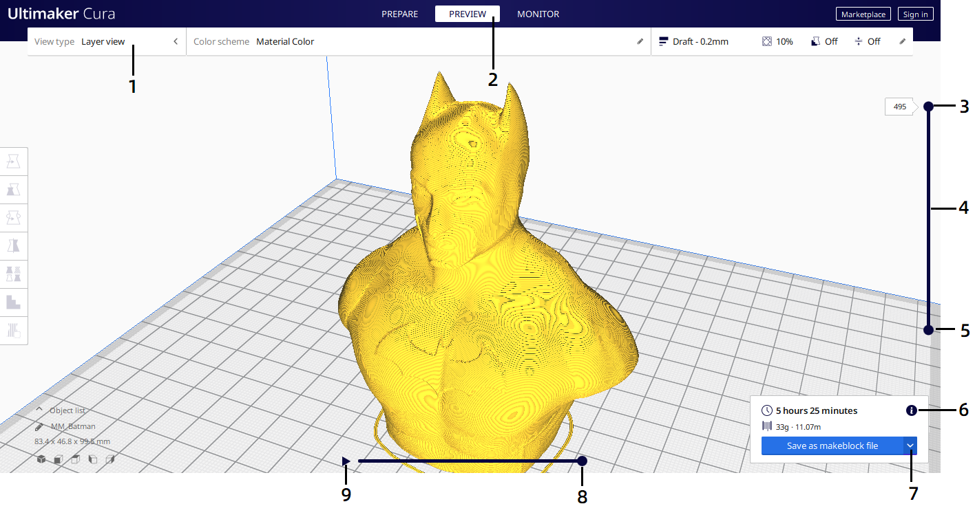
View types. This contains the view types, color scheme panel, and print settings panel.
- Stage. The current stage is highlighted.
- Layer slider input. This uses the numeric input to jump to the desired layer.
- The layer slider. This can be dragged to drag a layer range up and down.
- Layer slider handle. Both the top and bottom handle can be dragged to specify the visible layer range.
- Print information. Hover the mouse over the icon to view detailed print time information per printed feature.
- Save as makeblock format. Save to removable disk or save to file.
- Path slider. This indicates the current position of the simulation view. This handle can be dragged or moved with the ‘arrow keys’ or ‘shift + arrow keys’.
Start simulation. This starts the simulation of the currently active layer to provide visual feedback on the printing process.
Stage 3 Monitor
The monitor views 3D printer that printing via USB. The status of printer can be inspected in this stage.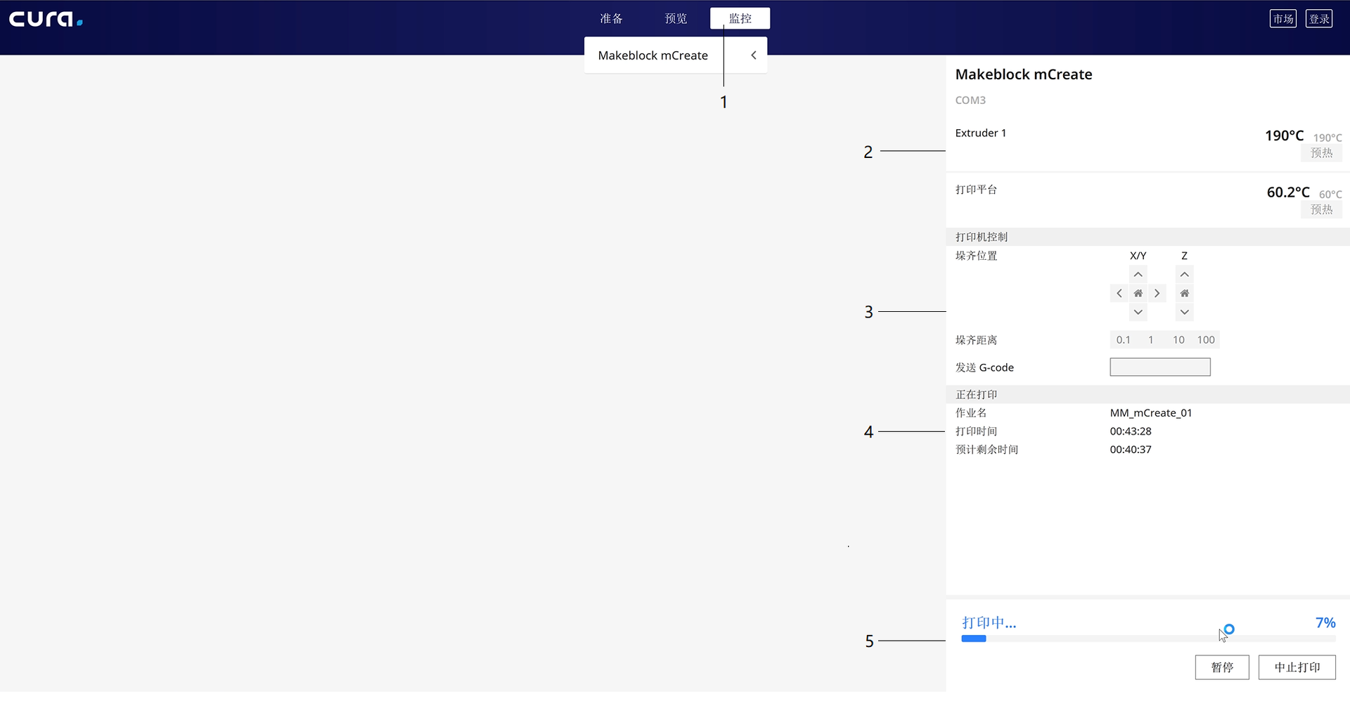
Stage. The current stage is highlighted.
- Printer information. Displays the printer name and temperatures.
- Printer control panel. Click the arrows to move the print head or build plate of the printer connected, or send G-Code to the printer.
- Active print. Displays name and print time of the print job.
- Print progess. Displays the progress of the print job.
Adjustment tools
Ultimaker Cura offers several tools to adjust the model before printing. This allows you to easily position, scale, and rotate models on the build plate in the most efficient way.
Move tool
You can position your model in any way you like using the move tool, which allows the model to be moved along its X, Y, and Z axes.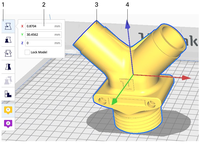
- Move tool. All selected models will be moved
- Number input field. can be used to set exact coordinates of the 3D model
- The 3D model. Once selected this can also be moved freely
Arrow handles. Drag these to move the model on any specific axis
Scale tool
The scale tool allows the model to be scaled in three different ways – in millimeters, as a percentage, and with the handles in the 3D viewer.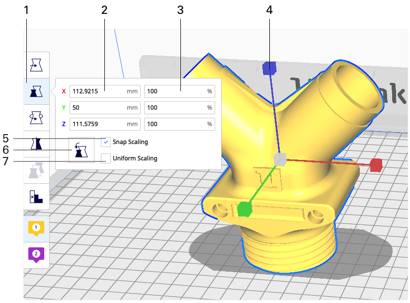
- Scale tool. All selected models will be scaled
- Number input field. Can be used to set the exact model size in millimeters
- Percentage input field. Can be used to set a percentage of the original model scale
- Scale handles. Drag these to scale the mode
- Snap scaling. This option will scale the the model by 10% at a time, when dragging the scale handles
- Reset. This will reset all scaling modifications to the selected models
Uniform scaling. This will ensure the model’s proportions are consistent while scaling
Rotate tool
The rotate tool allows the model to be rotated on all of its axes. This is particularly useful to reduce the amount of support needed or to increase the model’s footprint for better build plate adhesion.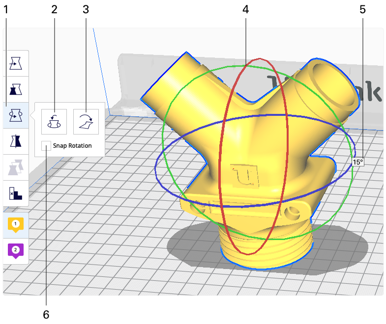
- Rotate tool. Rotate about the origin of selected models. This is different from individual rotating behavior
- Reset. Reset all rotations of the selected models
- Lay flat. This will lay the model flat on the closest flat surface of the model
- Rotate hoops. Drag these hoops to rotate the model on the selected axis
- Degree indicator. Indicates the current rotation
Snap rotation. Snaps the rotation intervals to 15°. You can hold shift to toggle snap rotation instead
Mirror tool
The mirror tool mirrors the on all 3 axes, X, Y, and Z.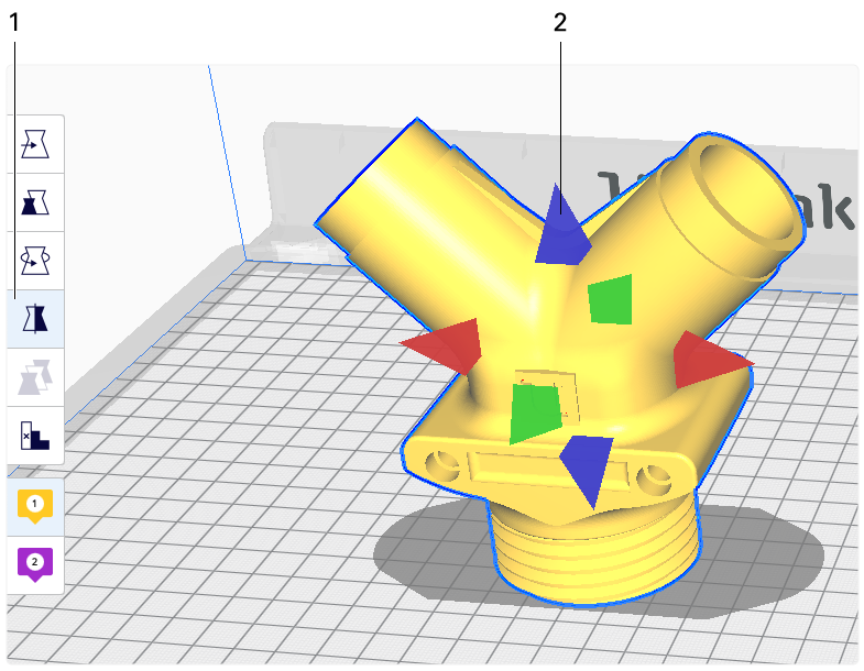
- Mirror tool. Mirror about the shared origin of the models. This is different from individual mirroring behavior
Mirror handle. Mirrors the model on the selected axis
Manage profiles
Ultimaker Cura provides the ability to save, share and manage your print profiles to keep an efficient workflow. This page explains how to work with profiles to get the most out of your 3D printing experience.
Quick menu
The easiest way to quickly create, update and save a profile is through the quick menu. It is also the easiest way to access the profile manager.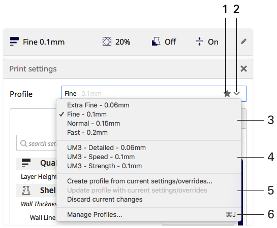
Star icon. Indicates the selected profile contains unsaved profile changes.
- Quick menu. Click here to access the quick menu.
- Default profiles. These profiles are distributed by Ultimaker.
- Custom profiles. These profiles are your user saved profiles.
- Create, update or discard current changes quickly, with the three options displayed here.
Manage profiles. Opens the profiles manager.
Print profile manager
The print profile manager contains all default and user saved profiles and allows to manage these in a convenient way.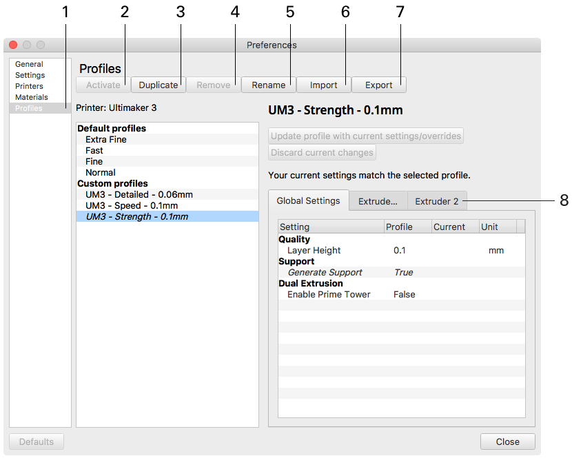
Settings
Cura provides many Settings to adjust the printing details of the model. In the preparation stage, click the Print settings panel to expand the print settings. You can change recommanded parameters in the panel. This section describes the meanings and effects of each parameter in the parameter setting panel.
Recommended settings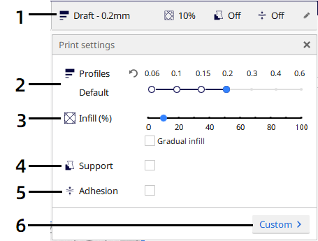
Print settings panel Displays parts of the settings.
- Profiles Displays the available profiles, Makeblock Plugin provides 4 different printing profiles.
- Density Infill density, defines the amount of material used on the inside.
- Support Print a support structure under the model
- Build plate adhesion The way how models adhere to the build plate, there three types of build plate adhesion.
Custom Click custom to go to Custom settings panel.
Custom settings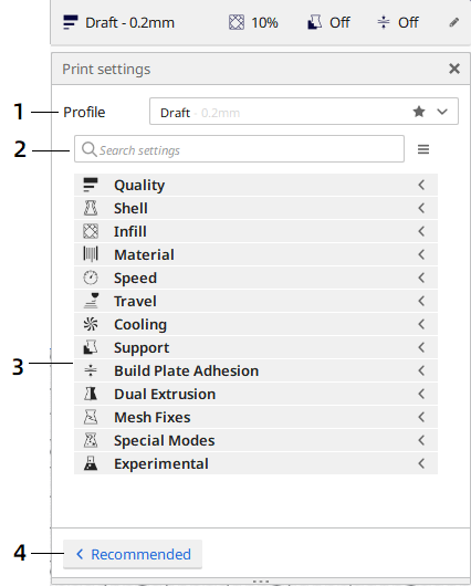
Profiles Displays the available profiles, Makeblock Plugin provides 4 different printing profiles. Click the arrow to change the profile.
- Search settings Search settings by keywords.
- Settings list You can modify settings in this list.
Recommended Click Recommended to go to Recommended settings panel.
QualityLayer height
The layer height is one of the most frequently changed settings. It is the thickness of one printed layer in millimeters. With a thinner layer height you can increase the quality of the print, leading to a smoother surface and more detail visible in the Z-direction (height) of the model. On the other hand, by using thicker layers you can decrease the print time substantially.
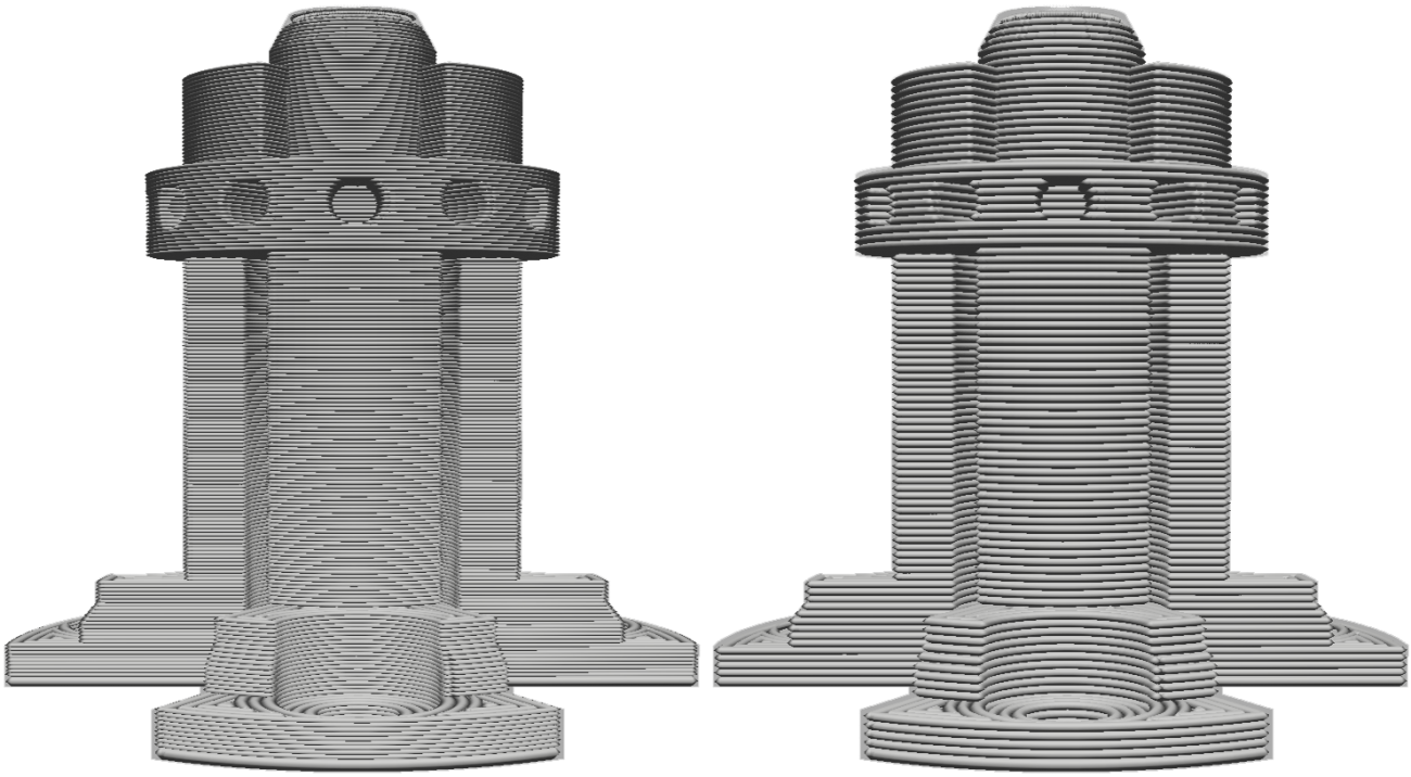
The model on the left has a bigger layer height than the model on the right.
The recommended mode allows the user to easily choose a layer height compatible with the current print core and material configuration. The number of available layer heights options differ per configuration. The custom mode allows the user to completely customize the layer height.
Note: In the custom mode, choose a layer height close to your desired custom layer height. The profile contains layer height dependent settings, like temperatures, to ensure a high-quality print.
Shell
- Wall thickness and wall line count
This setting adjusts the thickness of walls of the model. Ultimaker Cura rounds the wall thickness to a multiplication of the line width. In general, a wall thickness of two or three times the line width is sufficient. A higher value will create a sturdier model and decreases the chance of leaks, while a lower value can significantly decrease the print time and filament costs.
Instead of setting a thickness in millimeter of the walls, you can also set a number of walls. When you set the wall line count, the wall thickness is calculated and will grey out.
Example: A value of 1 mm, results in three walls of 0,35mm = 1,05mm wall. The model on the left has three walls, the model on the right has a single wall.
The model on the left has three walls, the model on the right has a single wall.
- Top/bottom thickness
With the top/bottom thickness you can set the thickness of the solidly printed top and bottom layers of the print. A higher value ensures all gaps on the top and bottom layers are closed completely. However, this can also increase the print time and amount of filament used.
It is advised to always use a multiple of the layer height for the thickness of the top and bottom. This means, for example, that with a layer height of 0.15 mm, it’s better to set the top/bottom thickness to 0.6 mm rather than 0.7 mm.
Infill
- Infill density
The infill density defines the amount of plastic used on the inside of the print. A higher infill density means that there is more plastic on the inside of your print, leading to a stronger object. An infill density around 20% is used for models with a visual purpose, higher densities can be used for end-use parts.
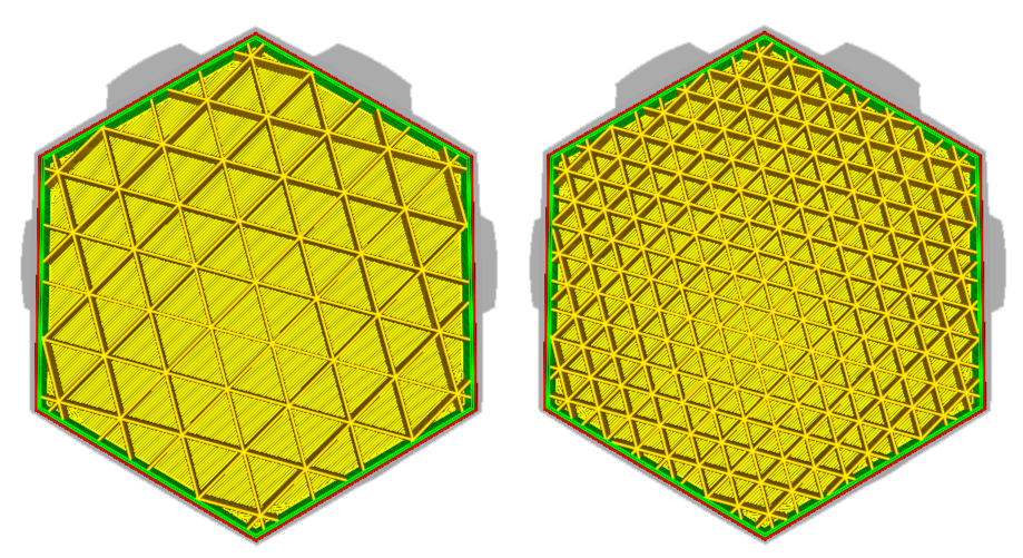
The model on the right has a higher infill density than the model on the left
- Infill pattern
Ultimaker Cura allows you to change the pattern of the printed infill structure, which is beneficial in some use cases. For example:
- Strong 2D infills are used for everyday prints
- Quick 2D infills are used for quick, but weak models
- 3D infills are used to make the object equally strong in all directions
- 3D concentric infills are used for flexible materials
The following pattern options are available:
- Grid: Strong 2D infill
- Lines: Quick 2D infill
- Triangles: Strong 2D infill
- Tri-hexagon: Strong 2D infill
- Cubic: Strong 3D infill
- Cubic (subdivision): Strong 3D infill (this saves material compared to Cubic)
- Octet: Strong 3D infill
- Quarter cubic: Strong 3D infill
- Concentric: Flexible 3D infill
- Zig-zag: A grid shaped infill, printing continuously in one diagonal direction
- Cross: Flexible 3D infill
- Cross 3D: Flexible 3D infill
- Gyroid infill: Infill with increased strength for the lowest weight.
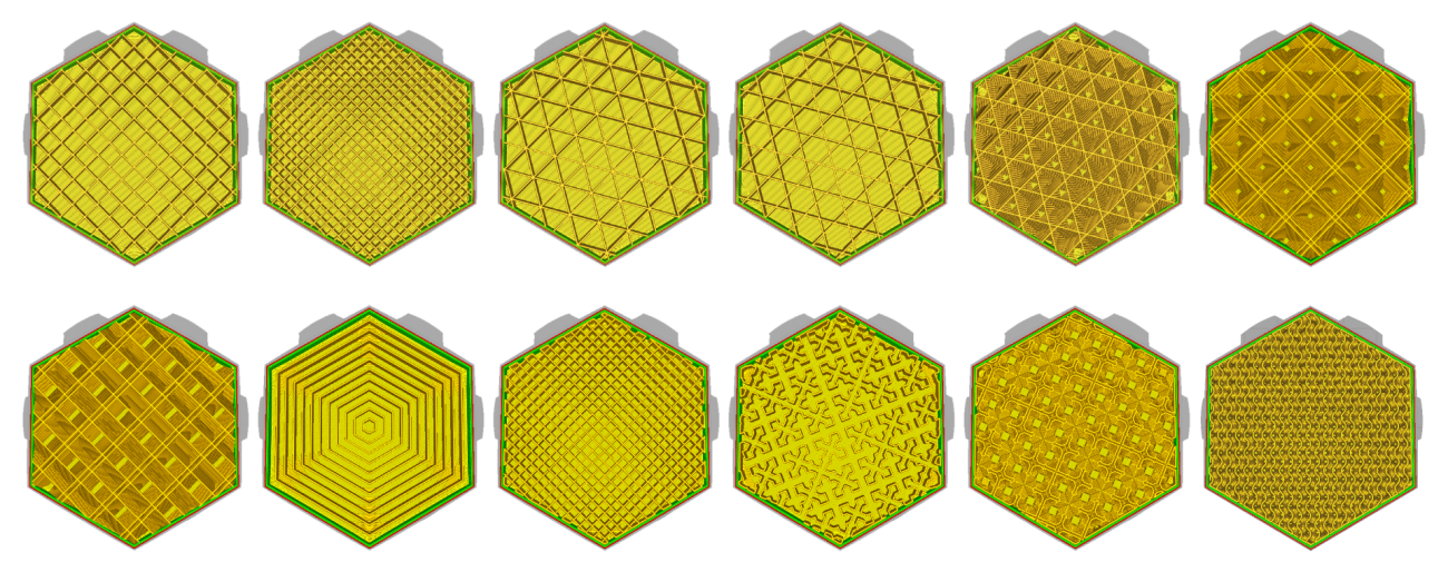
<br />The infill patterns are displayed in the order of the list above, from left to right.<br /> <br />**Material**
- Printing temperature
This refers to the temperature of the nozzle while printing, including the adapted extrusion rate. Each printing profile has a slightly different printing temperature to create the best print result.
- Build plate temperature
This setting defines the heated bed temperature during the printing process. Each material has an ideal build plate temperature, which is set here. When printing with two different materials, the temperature will be an average of the two. Changing this value is uncommon.
- Enable retraction
Retraction is used at the places in a print where the printer has to do a travel move between two printed parts. Without retraction, extruded material will hang between the parts. By using retraction, “stringing” (thin threads of plastic in between the printed parts) is prevented, resulting in a much cleaner model. Exercise caution when using flexible materials or models that require a lot of retractions as it may lead to grinding of the filament.
Speed
- Print speed
The print speed defines the speed (in mm/s) at which the print head moves while printing. Based on this setting, Ultimaker Cura calculates the extrusion flow. The print speed can be visualized per feature in the Layer view > Feedrate.
A higher print speed will lead to a shorter print time. Keep in mind that increasing the print speed means that you may have to increase the temperature as well to ensure the filament is properly melted.
Although you can choose one overall print speed for the complete print, it is also possible to use different print speeds for specific parts of the print:
Infill speed: The speed at which the infill material is printed. If the visual quality of the infill is not important, you could use a higher speed for the infill. However, keep in mind that this may affect the strength of your print.
- Outer wall speed: The speed at which the outer walls are printed. Printing the outer wall slower usually results in a better surface finish.
- Inner wall speed: The speed at which the inner walls are printed.
- Top/bottom speed: The speed at which the top and bottom layers are printed. A lower speed increases the reliability of closure on the top layers, especially for large-area prints.
- Top surface skin speed: The speed of the top surface skin layers. These have to be enabled in the shell category.
- Support infill speed: The speed at which support structures are printed. The quality of the support is not usually important, so a higher value can often be used here.
Support interface speed: The speed at which support roofs and bottoms are printed. Since these need to adhere to the model properly, they should be printed at a slower speed.
Travel
- Z-hop when retracted
With this setting, the print head will move up by the set value when a retraction is performed, allowing the print head to travel over the print without the nozzle touching it. This prevents the nozzle from hitting the object or leaving “blobs” or scratches on the print surface. Please note that for prints with lots of retractions/travel moves, this can increase the print time.
Support
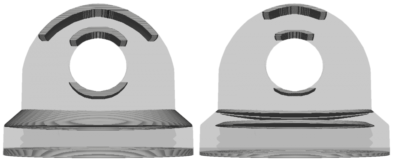
- Generate support
Some models have overhanging parts, which means that parts of the model float mid-air when you would print the model. In this case, you must print a support structure under the model to prevent the plastic from falling down. This can be achieved by enabling “Generate support”.
- Placement
This setting defines where the support structure is printed. It contains the following options:
- Touching build plate: Support material is only printed from the build plate up
Everywhere: Support material is printed below every part that needs support, which means that it can also be placed on or inside a model
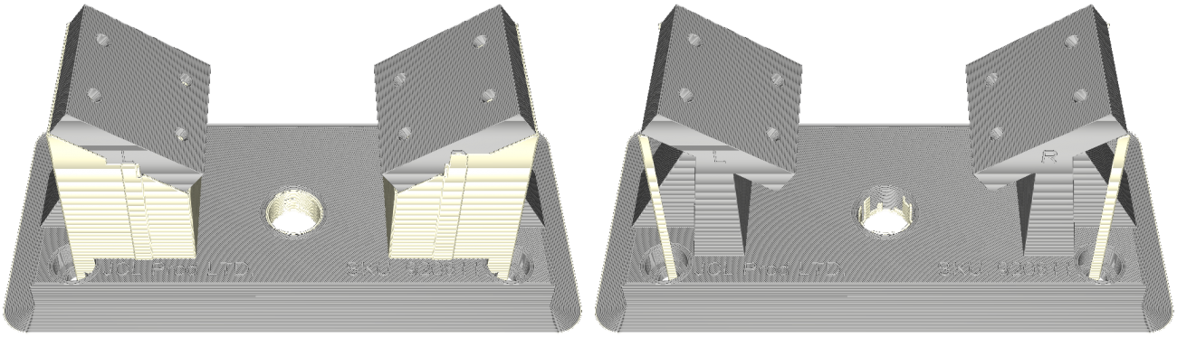 <br />This model has parts with overhangs. The model on the left has support everywhere, while the model on the right has support on the build plate only<br />
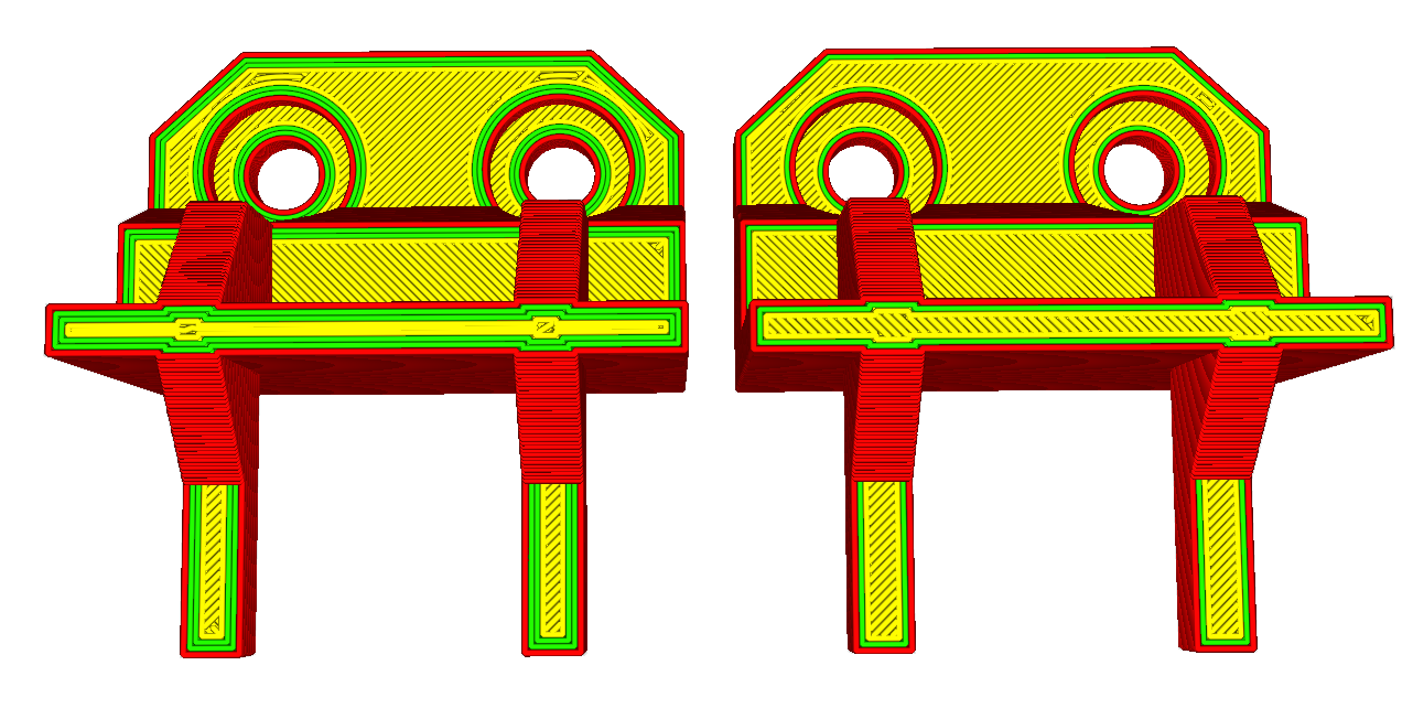
- Overhang angle
The overhang angle influences how much support material is added. A smaller angle leads to more support. For example, at a value of 0° all overhangs are supported, while at 90° no support material is added.
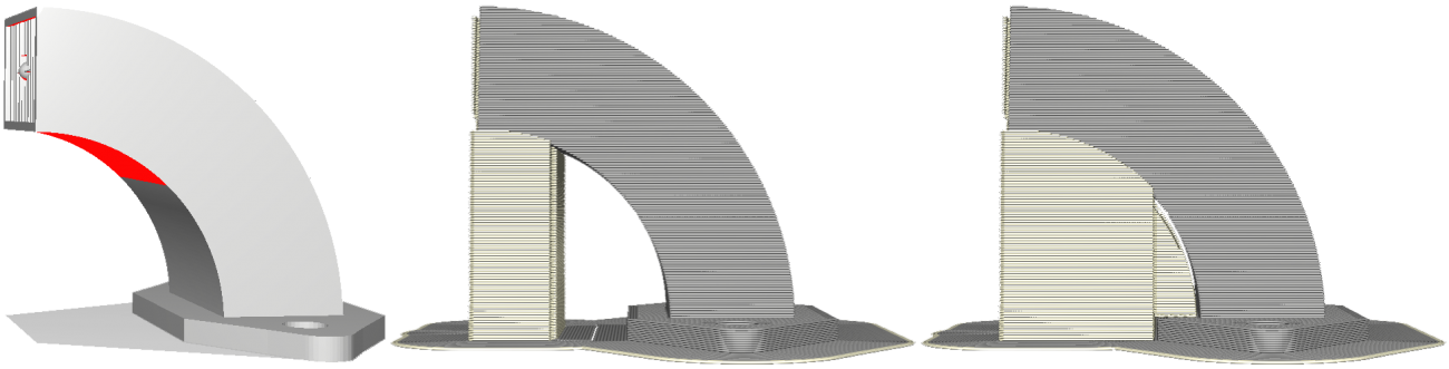
The model on the left is shown in the solid mode. The red areas indicate the overhang area that needs support. The model in the middle has an overhang angle of 70°, while the model on the right has an overhang angle of 45°
Cooling
- Enable cooling fans
With this setting you can enable or disable the print head fans during printing. The print head fans ensure that the material is cooled properly before the next layer is printed. For layers with a short layer time, and those with bridges/overhangs, cooling will increase the print quality.
- Fan speed
When the print head fans are enabled, you can adjust certain parameters. One of these is the fan speed – the speed at which the fans spin. A higher speed allows for better cooling and reduces oozing, but can also increase the shrinkage of the material. This is why the speed may be different for different materials. The preset material profiles on the Makeblock Plugin already contain the default values.
Build plate adhesion
- Build plate adhesion type
There are three types of build plate adhesion: skirt, brim and raft. You can also easily disable the adhesion types by setting it to None.
Skirt
A skirt is a line printed around the object on the first layer, but not connected to the object. This helps prime the extrusion nozzle and can be an additional check for bed leveling before the print begins.
Brim
Brim adds a single layer flat area around the base of the model to prevent warping. The brim is connected to the model and makes the bottom surface area bigger. This increases the adhesion to the build plate and, in case of warping, the corners of the model are less likely to curl up because of the brim attached to it.
Raft
A raft adds a thick grid with a roof between the model and the build plate. This can be useful when the bottom surface of a model is not completely flat or has little adhesion to the build plate. A raft ensures that the model will stick better to the build plate.
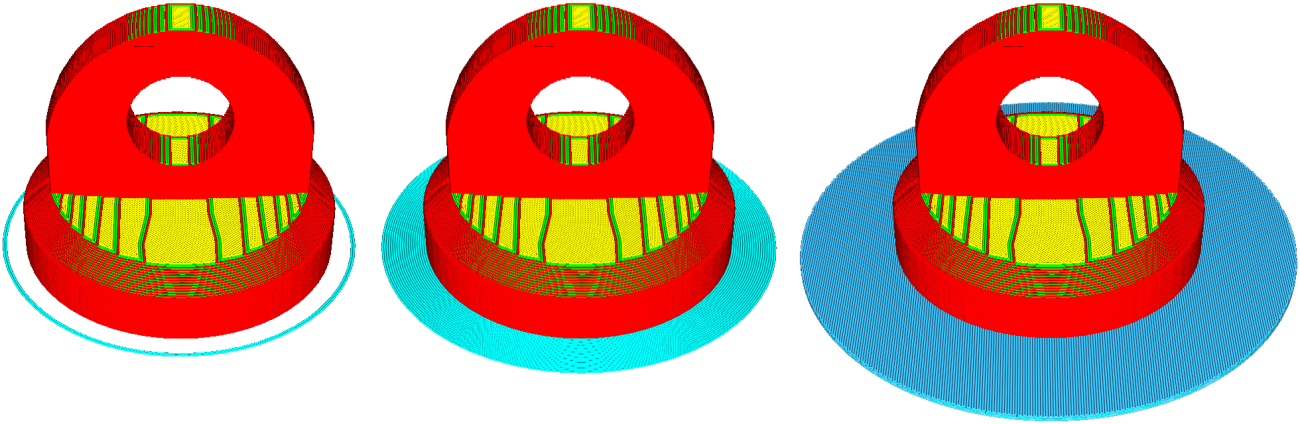
This model has the build plate adhesion types from left to right: skirt, brim and raft
Language setting
English is the default language for Cura. Go to Preference > Configure Cura. In the pop-up window, click the Language drop-down menu to select a language.
Use Laserbox for mCreate
Laser engrave via computer
- Import an image
Go to Menu > Import or drag the image into Laserbox for mCreate.
- Connect mCreate to your computer
When the connection is successful, a computer icon appears in the status bar on the touch screen. Meanwhile, the + icon at the upper right corner of the software window turns into ▶.
- Put in material
Place the material you want to engrave at the center of the build plate.
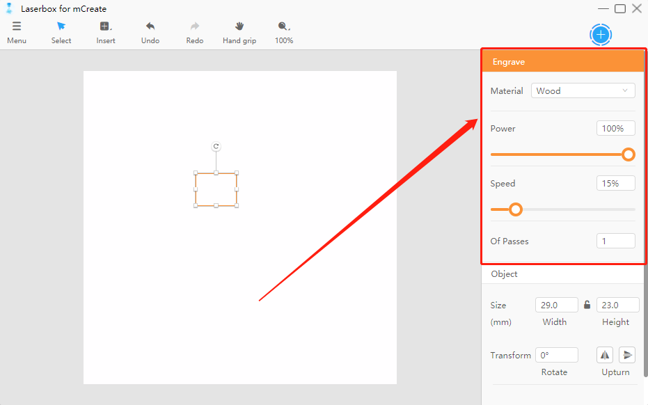
- Select material
Select the material to be engraved in the Material drop-down menu at the upper right corner of the interface. The software will then automatically configure the power and speed suited for the material. If you can’t find the material you need in the menu, drag the slider to define the engraving power and speed.
- Adjust focus
Click the start button at the top right corner of the software. The printer then starts focusing.
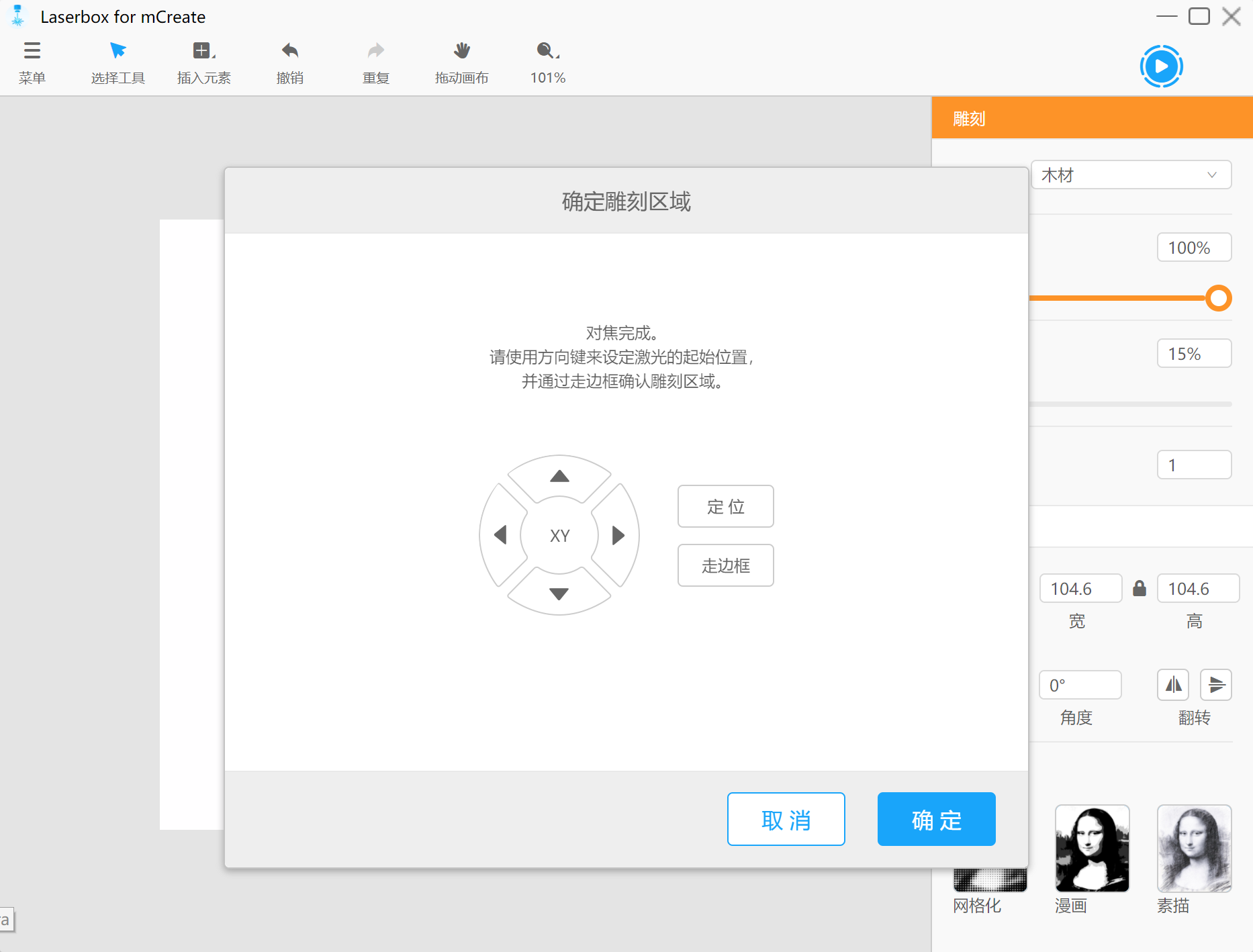
- Confirm engraving area
When focusing is complete, a Confirm engraving area window pops up.
- Arrow buttons Tap the buttons to control the position of the nozzle on the x and y axles.
- Position Locates the laser head and uses the current position as the initial point where bounding begins.
- Bound Indicates the area to be engraved for the current file.
- OK Instructs mCreate to start engraving.
- Cancel Resets the laser head and cancels the current engraving task.
- Start engraving
Click OK. Then you can see the estimated remaining time and the preview.
Click Start to start the current engraving task.
- Monitor the task
You can monitor the progress and view the remaining time during engraving.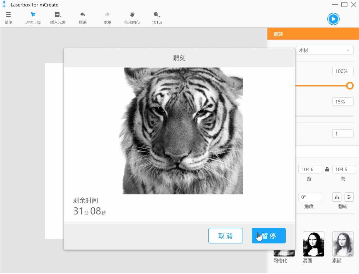
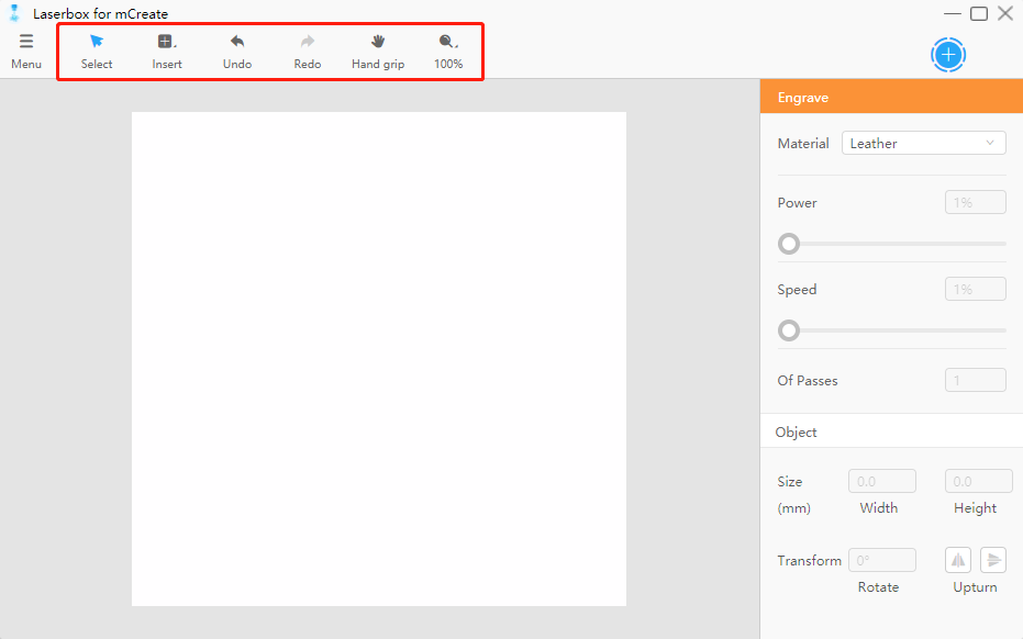
Interface overview
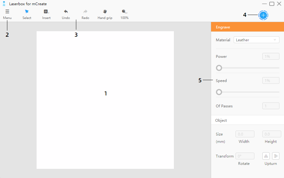
- Canvas This is where you design your model. Consider the canvas as micro build plate. So, if you draw a pattern at the upper left corner of the canvas, the pattern will be engraved at the same location of the plate.
- Menu Offers options such as Import, Export, and other settings.
Toolbar Includes frequently-used tools and actions options.
Start button Click this button to start an engraving task from your computer.
- Parameters panel You can configure engraving parameters and styles for the objects on the canvas.
- Canvas
Hand grip
In the toolbar, click Hand grip. Then left-click and drag on the canvas to move it. Or, hold down the Space key and the left mouse button at the same down to drag the canvas. 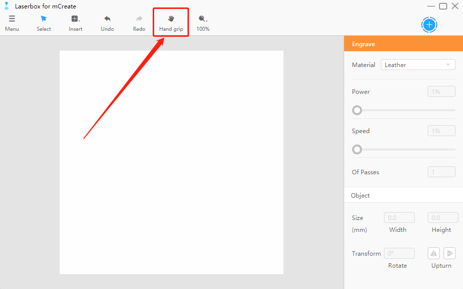
Zoom
In the toolbar, click the view tool, a magnifier icon, and select an option from the drop-down list to adjust the size of the canvas.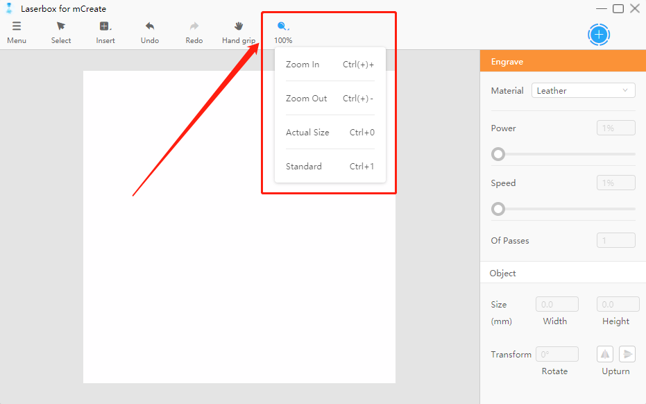
- Zoom In When the current size is smaller than 100%, the zoom value increases by 10% with each click on Zoom In; when the current size is over 100%, the zoom value increases by 50% with each click on the button.
- Zoom Out When the current size is smaller than 100%, the zoom value decreases by 10% with each click on Zoom Out; when the current size is over 150%, the zoom value decreases by 50% with each click on the button.
- Actual Size Restores the size to 100%.
Standard Adjusts the canvas to a size that fits the current window.
Auto-aligning and distance measuring
When you drag one of the two objects on the canvas, you can see alignment lines and distance between the two objects.
The alignment lines and distance also help keep two objects at the same height and width when you drag the anchor points to adjust their size.
- Menu
Menu offers most options you need to execute the features of Laserbox for mCreate.
- Import Click this button to import an image file into the canvas. The shortcut is [Ctrl] + [O]. Optionally, just drag the image into the canvas to import it.
- Export Converts the objects on the canvas into the format that mCreate can identify. Its shortcut is [Ctrl] + [E]. Click this option and save your file to a USB to print the object with mCreate later.
- Edit Offers commands to edit an object.
- View Used to zoom the canvas.
- Check For Updates Click this to see whether the current version is the latest.
- Language Allows you to switch interface language.
- Help Directs to the website where you can find help files about mCreate and Laserbox for mCreate.
- About Provides version information about Laserbox for mCreate.
- Exist Used to close Laserbox for mCreate.
- Toolbar
You can find the design tools in the toolbar.
- Select Used to select an object on the canvas. The Select tool is activated by default. You can click on an object or drag the cursor around an object to select it for further action.
- Insert Used to add different elements into the canvas.
- Undo Erases the last action you’ve done to the canvas.
- Redo Opposite of Undo. Click this to redo something you’ve undone.
- Hand grip Click this to activate the dragging feature. After clicking this tab, hold down the left mouse button and drag the canvas to view the objects.
- View Used to zoom the canvas.
- Parameters panel
Only when you select an object on the canvas will the parameters panel on the right side be activated. The panel comprises two parts: 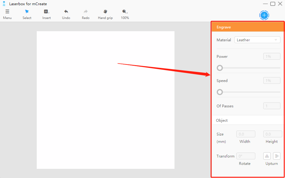
- Engraving parameters These parameters determine how the selected object will be engraved. You can adjust the settings of material, power, speed, and of passes.
- Style parameters Here offers options to define the style of the selected object. You can tune size, transform, fill the object, and change the filter.
Insert
An object can be a shape, picture, text, or line. In Laserbox for mCreate, you can adjust the engrave parameters such as power and speed in terms of objects. You can insert different objects and define their parameters to make your engravings more appealing.
Types of objects:
- Shapes Refer to vector shapes. Lines and curves are used to describe shapes. Shapes include dots, lines, rectangles, polygons, ovals, arcs, and more. No matter you enlarge, shrink, or rotate a shape, it won’t distort.
- Images Refer to bitmap images, which are made up of dots called pixels. Many images you see in everyday life are bitmaps. When you enlarge a bitmap, each pixel is enlarged as well. The lines and shapes then appear uneven, and the image gets distorted.
- Text In Laserbox for mCreate, text is a special form of shapes. So, you can not only adjust font and spacing but also fill the text with colors.
- Insert a shape
Click Insert and select a shape. Listed below are the shortcuts for different shapes:
| Types of shapes | Shortcuts |
|---|---|
| Line | [L] |
| Rectangle | [R] |
| Rounded | [U] |
| Oval | [O] |
| Star | [S] |
| Heart | [H] |
Left-click and drag on any blank space on the canvas to preview the shape. Then release the left mouse button to insert the shape.
- Insert an image
Go to Menu > Import, then select a file. Or, just drag the image file into the canvas. The shortcut to import is [Ctrl] + [O].
- Insert text
Select the Insert tab in the toolbar and click Text on the list. Or, just press [T] on your keyboard. Left-click on any blank space on the canvas to insert a text box. You can insert text in the text box. Click on the empty space to exit editing.
Export a file
Go to Menu > Export to export the objects and their parameter settings on the current canvas as a file for mCreate to engrave. The shortcut to export is [Ctrl] + [E].
Basic tools
Edit
Go to Menu > Edit. The shortcuts for the features:
| Actions | Shortcuts |
|---|---|
| Undo | [Ctrl] + [Z] |
| Redo | [Ctrl] + [Y] |
| Cut | [Ctrl] + [X] |
| Copy | [Ctrl] + [C] |
| Paste | [Ctrl] + [V] |
| Delete | [Delete] |
| Select All | [Ctrl] + [A] |
- Undo Click the Undo button on the toolbar to erase the last action you’ve done to the canvas. The shortcut to undo is [Ctrl] + [Z].
- Redo Opposite of Undo. Click this to redo something you’ve undone. The button is greyed out and unavailable if you haven’t undone any actions. The shortcut to redo is [Ctrl] + [Y].
- Cut Right-click on an object and select Cut. Then the object will be added to the clipboard and disappear on the canvas. The shortcut to cut a selected object is [Ctrl] + [X].
- Copy Right-click on an object and select Copy. A copy of the object will be added to the clipboard but the object remains on the canvas. The shortcut to copy a selected object is [Ctrl] + [C].
- Paste Right-click on anywhere on the canvas and select Paste. The object on the clipboard will be pasted on the canvas. The shortcut to paste an object is [Ctrl] + [V].
- Delete Right-click on the selected object and select Delete. You can also press [Delete] on your keyboard to remove the selected object.
- Select All Right-click on blank space and click Select All to select all the objects on the current canvas. The shortcut to select all the objects is [Ctrl] + [A].
Engraving parameters
Adjust the parameters of an object to create different engraving effects.
- Material Laserbox for mCreate has a parameter pool for commonly-used materials. After you select a material, the settings most suitable for engraving the materials, including power and speed, will automatically apply.
- Power Higher power means deeper engravings, and lower power means shallower engravings.
- Speed Higher speed leaves shallower engravings, and lower speed leaves deeper engravings.
- Of Passes Define the times that the selected object will be engraved. Multiple passes leave deeper engravings.
Style parameters
- Size
When you select an object, a set of anchor points appears on the frame of the object. Click on and drag the anchor points to adjust the size. For a more precise adjustment, use the parameters panel on the right side.
Click the lock-like icon in the size parameters to lock/unlock the aspect ratio. Under the locked status, the aspect ratio of the object doesn’t change when you drag its anchor points or change its size. Once the ratio is unlocked, you can adjust the height or width without changing the other one. When dragging the anchor point to resize the object, hold down Shift key to lock the aspect ratio. 
- Transform
- Rotate Click the rotation handle at the top of the selected object, and then drag in the direction you want. Specify a rotation angle in the parameters panel for more precise rotation.
- Upturn Click the Upturn button to flip the object. You can select flip horizontal or flip vertical.
- Fills
When the selected object is an enclosed shape or text, the Fills option appears on the parameters panel. Tick Fills to fill the shape or text.
- Crop
When the selected object is an image, you can crop it. Right-click on the object and select Crop to frame the part you want to keep. Then left-click on blank space. The part in the crop box will remain, while the one outside the box will be removed.
- Filter setting
When the selected object is an image, the Filter Setting appears in the parameters panel. Click on the options to add different filters to your image. To delete a applied filter, just click the filter option again.
- Text editing
When you select a text, the text editing options appear in the parameters panel. Click the text again to start editing it.
- Typeface Change the font for your text.
- Space Change the space between words and lines.
Language setting
The default language of Laserbox for mCreate is simplified Chinese. Go to the Menu tab, select Language in the drop-down menu, and select the language. The language immediately changes.
Makeblock Services
Please contact us if you find the actual product is inconsistent with the Manual during operation, or if you want to get the latest information, or have any questions or suggestions.
Technical support: support@makeblock.com
Note: The above information may be subject to change due to objective factors. Refer to the latest release of Makeblock. If you use the Internet or phone call to get our support, additional fees may apply.

若有收获,就点个赞吧
0 人点赞
