- MicroStation版本:10.16.02.34
- Element
- 1.1 DgnStoreHdrElement
- 1.2 DisplayableElement
- 1.2.1 AnnotationHandler
- 1.2.2 AreaFillPropertiesQuery
- 1.2.3 AssocRegionQuery
- 1.2.4 BRepEdit
- 1.2.5 BsplineSurfaceQuery
- 1.2.6 CellQuery
- 1.2.7 ComplexHeaderElement
- 1.2.8 ConeElement
- 1.2.9 CurveElement
- 1.2.10 CurvePathQuery
- 1.2.11 DimensionElement
- 1.2.12 DimensionQuery
- 1.2.13 EllipticArcBaseElement
- 1.2.14 ExtendedElementElement
- 1.2.15 LineElement
- 1.2.16 LineStringBaseElement
- 1.2.17 MaterialPropertiesExtension
- 1.2.18 MeshHeaderElement
- 1.2.19 MeshQuery
- 1.2.20 MultilineElement
- 1.2.21 MultilineQuery
- 1.2.22 ParametricCellElement
- 1.2.23 PointCloudElement
- 1.2.24 PointCloudQuery
- 1.2.25 PointStringElement
- 1.2.26 RasterAttachmentQuery
- 1.2.27 RasterFrameElement
- 1.2.28 RasterHeaderElement
- 1.2.29 SharedCellElement
- 1.2.30 SharedCellQuery
- 1.2.31 SolidPrimitiveQuery
- 1.2.32 TagElement
- 1.2.33 TextHandlerBase
- 1.2.34 TextQuery
- 1.2.35 TextTableElement
- 1.3 ExtendedNonGraphicsElement
- 1.4 ParametricCellDefinitionElement
- 2.Element 属性
MicroStation版本:10.16.02.34
Element
说明:
基本单位
方法:
| public StatusInt AddToModel( ) |
|---|
功能说明:
将该元素添加到当前激活的模型空间中
输入:
无
输出:
StatusInt: 写入结果反馈
示例:
private void AddToModelExample(){DgnModel dgnModel = Session.Instance.GetActiveDgnModel();//获得当前激活的模型空间Bentley.DgnPlatformNET.Elements.Element elem = new Bentley.DgnPlatformNET.Elements.EllipseElement(dgnModel, null, DPoint3d.Zero, 10000, 5000, 0);//创建椭圆元素elem.AddToModel();//将椭圆元素写入模型}
| public StatusInt AppendLinkage( ushort linkageId, WriteDataBlock data ) |
|---|
功能说明:
将数据链接到元素上
输入:
ushort linkageId: 链接ID
WriteDataBlock data: 需要写入的数据块
输出:
StatusInt: 写入结果反馈,若添加链接将超过最大元素大小时出错
示例:
private void AppendLinkageExample(){System.UInt16 s_linkageId = 22269;//设置linkageIDbyte[] s_writeByteArray = new byte[] { 1, 2, 3, 4, 5, 6, 7, 8, 9, 10, 11, 12, 13, 14 };//设置写入Byte数组System.Int16[] s_writeInt16Array = new System.Int16[] { 24000, 25000, 26000, 27000, 28000, 29000, 30000, 31000, 32000 };//设置写入Int数组int[] s_writeInt32Array = new int[] { 110000, 120000, 130000, 140000, 150000, 160000 };//设置写入Int数组System.Int64[] s_writeInt64Array = new System.Int64[] { 3000000000, 3100000000, 3200000000, 3300000000, 3400000000, 3500000000, 3600000000 };//设置写入Int数组float[] s_writeFloatArray = new float[] { (float)210000.0, (float)220000.0, (float)230000.0, (float)240000.0, (float)250000.0, (float)260000.0 };//设置写入float数组double[] s_writeDoubleArray = new double[] { 310000.0, 320000.0, 330000.0, 340000.0, 350000.0, 360000.0, 370000.0, 380000.0, 390000.0, 400000.0 };//设置写入double数组string s_shortString = "Short";//设置写入短string值string s_mediumString = "This is a medium string";//设置写入中string值string s_longString = "This is a longer string with quite a few characters that is used for testing the WriteString method on WriteDataBlock.";//设置写入长string值DSegment3d segment = new DSegment3d(0, 0, 0, 1000, 0, 0);//声明一个几何直线LineElement line = new LineElement(Session.Instance.GetActiveDgnModel(), null, segment);//声明一个线元素line.AddToModel();//将线元素写入模型Bentley.DgnPlatformNET.Elements.WriteDataBlock dataBlock = new Bentley.DgnPlatformNET.Elements.WriteDataBlock();//声明一个数据写入块dataBlock.WriteByte(10);//写入数据dataBlock.WriteByteArray(s_writeByteArray);dataBlock.WriteInt16(200);dataBlock.WriteInt16Array(s_writeInt16Array);dataBlock.WriteInt32(2000);dataBlock.WriteInt32Array(s_writeInt32Array);dataBlock.WriteInt64(200000000000);dataBlock.WriteInt64Array(s_writeInt64Array);dataBlock.WriteFloat((float)3000.0);dataBlock.WriteFloatArray(s_writeFloatArray);dataBlock.WriteDouble(4000.0);dataBlock.WriteDoubleArray(s_writeDoubleArray);dataBlock.WriteString(s_shortString);dataBlock.WriteString(s_mediumString);dataBlock.WriteString(s_longString);dataBlock.WriteInt16(1000);line.AppendLinkage(s_linkageId, dataBlock);//对线施加Linkageline.AddToModel();//将线元素写入模型}
| public int ApplyTransform( TransformInfo transform ) |
|---|
功能说明:
对几何元素应用矩阵变换
输入:
TransformInfo transform: 施加的变换信息
输出:
int: 变换结果反馈
示例:
private void ApplyTransformExample(){DgnModel dgnModel = Session.Instance.GetActiveDgnModel();//获得当前激活的模型空间Bentley.DgnPlatformNET.Elements.Element elem = new Bentley.DgnPlatformNET.Elements.EllipseElement(dgnModel, null, DPoint3d.Zero, 10000, 5000, 0);//声明一个椭圆元素DTransform3d transform = DTransform3d.FromTranslation(new DPoint3d(100, 100, 100));//创建矩阵变换,在这里创建了一个用于平移的变换矩阵TransformInfo tInfo = new TransformInfo(transform);//声明变换信息int result = elem.ApplyTransform(tInfo);//对椭圆元素施加变换信息elem.AddToModel();//将变换后的元素写入模型}
| public void ConvertTo2d( ref DTransform3d flattenTrans, ref DVector3d flattenDir ) |
|---|
功能说明:
将3D元素转换为其2D形式
输入:
ref DTransform3d flattenTrans:(引用)应用矩阵变换将元素转换成平面
ref DVector3d flattenDir:(引用)确定所生成平面的法线方向
输出:
无
示例:
private void ConvertTo2dExample(){DPoint3d[] points = { new DPoint3d(0, 0, 0), new DPoint3d(100, 100, 100), new DPoint3d(150, 200, 50), new DPoint3d(200, 250, 300) };//创建一个坐标点数组LineStringElement lineString = new LineStringElement(Session.Instance.GetActiveDgnModel(), null, points);//创建线串元素DTransform3d trans = DTransform3d.Identity;//声明变换矩阵DVector3d vector = DVector3d.UnitZ;//声明向量lineString.ConvertTo2d(ref trans, ref vector);//将线转成2D形式lineString.ConvertTo3d(0);//将线转成3D形式lineString.AddToModel();//将线串元素写入模型空间}
| public void ConvertTo3d( double elevation ) |
|---|
功能说明:
将2D元素转换为3D形式
输入:
double elevation:应用于2D元素上的Z坐标值
输出:
无
示例:
private void ConvertTo3dExample(){DPoint3d[] points = { new DPoint3d(0, 0, 0), new DPoint3d(100, 100, 100), new DPoint3d(150, 200, 50), new DPoint3d(200, 250, 300) };//创建坐标点数组LineStringElement lineString = new LineStringElement(Session.Instance.GetActiveDgnModel(), null, points);//创建线串元素DTransform3d trans = DTransform3d.Identity;//声明变换矩阵DVector3d vector = DVector3d.UnitZ;//声明三维向量lineString.ConvertTo2d(ref trans, ref vector);//将线串元素垂直于向量方向转换为2D形式lineString.ConvertTo3d(0);//将线串元素转换为3D形式(若不执行转换直接导入三维模型会报错)lineString.AddToModel();//将线串元素导入模型}
| public StatusInt DeleteFromModel( ) |
|---|
功能说明:
将元素从所在模型空间中删除
输入:
无
输出:
StatusInt: 删除结果反馈
示例:
private void DeleteFromModelExample(){Bentley.DgnPlatformNET.Elements.Element elem = new Bentley.DgnPlatformNET.Elements.EllipseElement(Session.Instance.GetActiveDgnModel(), null, DPoint3d.Zero, 10000, 5000, 0);//创建一个椭圆元素elem.AddToModel();//将椭圆元素写入模型elem.DeleteFromModel();//把椭圆元素写入模型}
| public StatusInt DeleteLinkage( ushort linkageId ) |
|---|
功能说明:
移除元素上存在的数据链接
输入:
ushort linkageId: 链接ID
输出:
StatusInt: 删除结果反馈
示例:
private void DeleteLinkageExample(){System.UInt16 s_linkageId = 22269;//设置LinkIDDSegment3d segment = new DSegment3d(0, 0, 0, 1000, 0, 0);//创建几何直线LineElement line = new LineElement(Session.Instance.GetActiveDgnModel(), null, segment);//创建线元素WriteDataBlock dataBlock = new WriteDataBlock();//声明数据写入块dataBlock.WriteByte(10);//写入Byte数据line.AppendLinkage(s_linkageId, dataBlock);//对线元素添加Linkline.AddToModel();//将线元素写入模型空间line.DeleteLinkage(s_linkageId);//移除线元素上的Linkline.AddToModel();//将线元素写入模型空间}
| public StatusInt DeleteLinkage( ushort linkageId, int index ) |
|---|
功能说明:
仅删除数据链接ID中指定索引条目中的链接信息
输入:
ushort linkageId: 链接ID
int index:链接信息的索引值
输出:
StatusInt: 删除结果反馈
示例:
private void DeleteLinkageExample2(){System.UInt16 s_linkageId = 22269;//设置LinkIDDSegment3d segment = new DSegment3d(0, 0, 0, 1000, 0, 0);//创建几何直线LineElement line = new LineElement(Session.Instance.GetActiveDgnModel(), null, segment);//创建线元素WriteDataBlock dataBlock = new WriteDataBlock();//声明数据写入块dataBlock.WriteByte(10);//写入Byte数据line.AppendLinkage(s_linkageId, dataBlock);//对线元素添加Linkline.AppendLinkage(s_linkageId, dataBlock);//对线元素添加Linkline.AddToModel();//将线元素写入模型空间int nLinkages = line.GetLinkageCount(s_linkageId);//获得ID为22269的Link总数for (int count = nLinkages - 1; count > 0; count--)//遍历获得的Link{line.DeleteLinkage(s_linkageId, count);//删除Linkline.AddToModel();//将线元素写入模型空间}}
| public void Dispose( ) |
|---|
功能说明:
手动释放元素占用资源
输入:
无
输出:
无
示例:
private void DisposeExample(){Bentley.DgnPlatformNET.Elements.Element elem = new Bentley.DgnPlatformNET.Elements.EllipseElement(Session.Instance.GetActiveDgnModel(), null, DPoint3d.Zero, 10000, 5000, 0);//创建椭圆元素elem.AddToModel();//将椭圆元素写入模型空间elem.Dispose();//清空内存中的椭圆元素}
| public bool ExposeChildren( ExposeChildrenReason reason ) |
|---|
功能说明:
确定此元素的子元素是否向调用者暴露
输入:
ExposeChildrenReason reason:访问该元素下子元素的原因
输出:
bool:若元素中因输入原因应被暴露,则返回true
示例:
private void ExposeChildrenExample(){LineElement line1 = new LineElement(Session.Instance.GetActiveDgnModel(), null, new DSegment3d(0, 0, 0, 500, 0, 0));//创建线元素LineElement line2 = new LineElement(Session.Instance.GetActiveDgnModel(), null, new DSegment3d(500, 0, 0, 1000, 500, 0));LineElement line3 = new LineElement(Session.Instance.GetActiveDgnModel(), null, new DSegment3d(1000, 500, 0, 1500, 500, 0));List<Bentley.DgnPlatformNET.Elements.Element> elems = new List<Bentley.DgnPlatformNET.Elements.Element>() { line1, line2, line3 };//创建线元素列表CellHeaderElement cellElem = new CellHeaderElement(Session.Instance.GetActiveDgnModel(), "Test", new DPoint3d(2000, 0, 0), DMatrix3d.Identity, elems);//创建单元cellElem.AddToModel();//将单元写入模型bool isExposed = cellElem.ExposeChildren(ExposeChildrenReason.Query);//确定此元素的子元素是否向调用者暴露int count = 0;//声明int值foreach (Element child in cellElem.GetChildren())//遍历单元中的子元素{count++;//int自增}MessageCenter.Instance.ShowMessage(MessageType.Info,"The child element number of the element is " + count,"The child element number of the element is " + count, MessageAlert.Dialog);//对话框提示该元素的子元素个数}
| public ChildElementCollection GetChildren( ) |
|---|
功能说明:
获得该元素下属的所有子元素
输入:
无
输出:
ChildElementCollection:子元素集
示例:
private void GetChildrenExample(){LineElement line1 = new LineElement(Session.Instance.GetActiveDgnModel(), null, new DSegment3d(0, 0, 0, 500, 0, 0));//创建线元素LineElement line2 = new LineElement(Session.Instance.GetActiveDgnModel(), null, new DSegment3d(500, 0, 0, 1000, 500, 0));LineElement line3 = new LineElement(Session.Instance.GetActiveDgnModel(), null, new DSegment3d(1000, 500, 0, 1500, 500, 0));List<Element> elems = new List<Element>() { line1, line2, line3 };//创建线元素列表CellHeaderElement cellElem = new CellHeaderElement(Session.Instance.GetActiveDgnModel(), "Test", new DPoint3d(2000, 0, 0), DMatrix3d.Identity, elems);//创建单元元素cellElem.AddToModel();//将单元元素写入模型空间ChildElementCollection childElems = cellElem.GetChildren();//获得该元素下属的所有子元素MessageCenter.Instance.ShowMessage(MessageType.Info,"The child element number of the element is " + childElems.Count(),"The child element number of the element is " + childElems.Count(), MessageAlert.Dialog);//对话框提示该元素的子元素个数}
| public List |
|---|
功能说明:
获得该元素所有的从属属性元素
输入:
无
输出:
List
示例:
private void GetDependantsExample(){LineElement line = new LineElement(Session.Instance.GetActiveDgnModel(), null, new DSegment3d(0, 0, 0, 500, 0, 0));//声明线元素line.AddToModel();//将线元素写入模型空间List<Element> dependEle = line.GetDependants();//获得该元素所有的从属属性元素MessageCenter.Instance.ShowMessage(MessageType.Info,"The dependant element number of the element is " + dependEle.Count(),"The dependant element number of the element is " + dependEle.Count(), MessageAlert.Dialog);//对话框提示该元素所有的从属属性元素个数DgnTagDefinition[] tagDefs = new DgnTagDefinition[1];//声明标注定义数组tagDefs[0] = new DgnTagDefinition();//声明标注定义tagDefs[0].Name = "Line";//设置标注名称tagDefs[0].Prompt = "LineSet";//设置标注提示tagDefs[0].TagDataType = TagType.Double;//设置标注数据类型tagDefs[0].Value = 1;//设置标注值TagSetElement tagSet = new TagSetElement(Session.Instance.GetActiveDgnModel(), tagDefs, tagDefs[0].Name, "", true, Session.Instance.GetActiveDgnFile(), 0);//声明标注元素tagSet.AddToModel();//将标注元素写入模型空间DPoint3d origin = DPoint3d.FromXYZ(0, 0, 0);//声明坐标点DMatrix3d orientation = DMatrix3d.Identity;//声明变换矩阵DgnTextStyle style = DgnTextStyle.GetSettings(Session.Instance.GetActiveDgnFile());//获得文件的文字样式TagElement tag = new TagElement(Session.Instance.GetActiveDgnModel(), null, tagSet.SetName, tagSet.SetName, null, style, false, origin, orientation, line);//声明标注元素tag.SetTagValue(1);//设置标注值,若不调用该方法,则将会使用默认值tag.AddToModel();//将标注元素写入模型dependEle = line.GetDependants();//获得该元素所有的从属属性元素"MessageCenter.Instance.ShowMessage(MessageType.Info,"The dependant element number of the element is " + dependEle.Count(),"The dependant element number of the element is " + dependEle.Count(), MessageAlert.Dialog);//对话框提示该元素所有的从属属性元素个数}
| public static Element GetFromElementRef( IntPtr elementRef ) |
|---|
功能说明:
获得指针指向的元素
输入:
IntPtr elementRef:需要从元素中获得样式的指针
输出:
Element:具有上述元素样式的元素
示例:
private void GetFromElementRefExample(){LineElement line1 = new LineElement(Session.Instance.GetActiveDgnModel(), null, new DSegment3d(0, 0, 0, 500, 0, 0));//声明线元素using (ElementPropertiesSetter setter = new ElementPropertiesSetter())//声明元素属性定义器{setter.SetColor(3);//使用颜色索引设置颜色setter.Apply(line1);//对线元素应用属性定义}line1.AddToModel();//将线元素写入模型IntPtr elementRef = line1.GetNativeElementRef();//获得线元素的指针Element line2 = Element.GetFromElementRef(elementRef);//根据指针获取模型line2.AddToModel();//将获取到的线元素写入模型}
| public static Element GetFromElementRefAndModelRef( IntPtr elementRef, IntPtr modelRef ) |
|---|
功能说明:
获得指针指向的模型空间中的指针指向的元素
输入:
IntPtr modelRef:指向特定模型空间的指针
IntPtr elementRef:需要从元素中获得样式的指针
输出:
Element:具有上述元素样式的元素
示例:
private void GetFromElementRefAndModelRefExample(){DgnModel dgnModel = Session.Instance.GetActiveDgnModel();//获取当前的模型空间IntPtr intPtrModel = dgnModel.GetNative();//获得指向模型的指针LineElement line1 = new LineElement(dgnModel, null, new DSegment3d(0, 0, 0, 500, 0, 0));//声明线元素using (ElementPropertiesSetter setter = new ElementPropertiesSetter())//声明元素属性定义器{setter.SetColor(3);//使用颜色索引设置颜色setter.Apply(line1);//对线元素应用属性定义}line1.AddToModel();//将线元素写入模型IntPtr intPtrElem = line1.GetNativeElementRef();//获得指向线元素的指针Element line2 = Element.GetFromElementRefAndModelRef(intPtrElem, intPtrModel);//根据模型与元素指针获得元素line2.AddToModel();//将元素写入模型空间}
| public ReadDataBlock GetLinkage( ushort linkageId ) |
|---|
功能说明:
获得指定元素上是否具有ID号为linkageId的链接信息
输入:
ushort linkageId: 链接ID
输出:
ReadDataBlock:用于读取链接信息
示例:
private void GetLinkageExample(){System.UInt16 s_linkageId = 22269;//声明链接ID值DSegment3d segment = new DSegment3d(0, 0, 0, 1000, 0, 0);//声明几何直线LineElement line = new LineElement(Session.Instance.GetActiveDgnModel(), null, segment);//声明线元素WriteDataBlock dataBlock = new WriteDataBlock();//声明数据写入块dataBlock.WriteByte(10);//写入Byte值line.AppendLinkage(s_linkageId, dataBlock);//将Link添加到线元素中ReadDataBlock readDataBlock = line.GetLinkage(s_linkageId);//获得指定元素上是否具有ID号为linkageId的链接信息byte info = readDataBlock.ReadByte();//读取线元素上链接的Byte值MessageCenter.Instance.ShowMessage(MessageType.Info,"Byte linkage is " + info,"Byte linkage is " + info, MessageAlert.Dialog);//对话框输出指定元素上是否具有ID号为linkageId的Byte值}
| public ReadDataBlock GetLinkage( ushort linkageId, int index ) |
|---|
功能说明:
获得指定元素上是否具有ID号为linkageId上指定索引号的链接信息
输入:
ushort linkageId: 链接ID
int index:链接信息的索引值
输出:
ReadDataBlock:用于读取链接信息
示例:
private void GetLinkageExample2(){System.UInt16 s_linkageId = 22269;//声明链接ID值DSegment3d segment = new DSegment3d(0, 0, 0, 1000, 0, 0);//声明几何直线LineElement line = new LineElement(Session.Instance.GetActiveDgnModel(), null, segment);//声明线元素WriteDataBlock dataBlock = new WriteDataBlock();//声明数据写入块dataBlock.WriteByte(10);//写入Byte值line.AppendLinkage(s_linkageId, dataBlock);//将Link添加到线元素中line.AppendLinkage(s_linkageId, dataBlock);//将Link添加到线元素中int nLinkages = line.GetLinkageCount(s_linkageId);//获得线元素上的链接个数for (int count = nLinkages - 1; count >= 0; count--)//遍历线元素上的链接{ReadDataBlock readDataBlock = line.GetLinkage(s_linkageId, count);//获得指定元素上是否具有ID号为linkageId上指定索引号的链接信息byte info = readDataBlock.ReadByte();//读取线元素上链接的Byte值MessageCenter.Instance.ShowMessage(MessageType.Info,"Index " + count + " byte linkage is " + info,"Index " + count + " byte linkage is " + info, MessageAlert.Dialog);//对话框提示索引与对应的链接值}}
| public int GetLinkageCount( ushort linkageId ) |
|---|
功能说明:
获得ID号为linkageId上的链接信息总数
输入:
ushort linkageId: 链接ID
输出:
int: ID号为linkageId上的链接信息总数
示例:
private void GetLinkageCountExample(){System.UInt16 s_linkageId = 22269;//声明链接ID值DSegment3d segment = new DSegment3d(0, 0, 0, 1000, 0, 0);//声明几何直线LineElement line = new LineElement(Session.Instance.GetActiveDgnModel(), null, segment);//声明线元素WriteDataBlock dataBlock = new WriteDataBlock();//声明数据写入块dataBlock.WriteByte(10);//写入Byte值line.AppendLinkage(s_linkageId, dataBlock);//将Link添加到线元素中line.AppendLinkage(s_linkageId, dataBlock);//将Link添加到线元素中int nLinkages = line.GetLinkageCount(s_linkageId);//获得线元素上的链接个数MessageCenter.Instance.ShowMessage(MessageType.Info,"The sum of linkage in the element is " + nLinkages,"The sum of linkage in the element is " + nLinkages, MessageAlert.Dialog);//对话框提示线元素上的链接总数}
| public ushort[ ] GetLinkageIds( ) |
|---|
功能说明:
获得元素上被赋予所有的链接ID号
输入:
无
输出:
ushort[ ]:由元素上被赋予的链接ID组成的数组
示例:
private void GetLinkageIdsExample(){System.UInt16 s_linkageId = 22269;//声明链接ID值DSegment3d segment = new DSegment3d(0, 0, 0, 1000, 0, 0);//声明几何直线LineElement line = new LineElement(Session.Instance.GetActiveDgnModel(), null, segment);//声明线元素WriteDataBlock dataBlock = new WriteDataBlock();//声明数据写入块dataBlock.WriteByte(10);//写入Byte值line.AppendLinkage(s_linkageId, dataBlock);//将Link添加到线元素中line.AppendLinkage(s_linkageId, dataBlock);//将Link添加到线元素中ushort[] links = line.GetLinkageIds();//获取线元素上的链接ID号的数组foreach (ushort link in links)//遍历链接ID数组{MessageCenter.Instance.ShowMessage(MessageType.Info,"The linkage id in the element is " + link,"The linkage id in the element is " + link, MessageAlert.Dialog);//对话框提示线元素上的链接ID号}}
| public IntPtr GetNativeDgnModelRef( ) |
|---|
功能说明:
获得元素所在模型空间的指针
输入:
无
输出:
IntPtr:元素所在模型空间的指针
示例:
private void GetNativeDgnModelRefExample(){DSegment3d segment = new DSegment3d(0, 0, 0, 1000, 0, 0);//声明几何直线DgnModel newModel = Session.Instance.GetActiveDgnFile().CreateNewModel(out DgnModelStatus status, "test", DgnModelType.Normal, true, null);//在激活的文件中创建模型LineElement line = new LineElement(newModel, null, segment);//在新模型中声明线元素DgnModelRef model = DgnModel.GetModelRef(line.GetNativeDgnModelRef());//获得线元素所在模型空间的指针using (ElementCopyContext eleCopyCon = new ElementCopyContext(line.DgnModelRef))//声明元素复制环境{eleCopyCon.SetDestinationModelRef(model);//设置复制目标模型eleCopyCon.DoCopy(line);//复制元素}}
| public IntPtr GetNativeElementRef( ) |
|---|
功能说明:
获得元素指针
输入:
无
输出:
IntPtr:指向元素的指针
示例:
private void GetNativeElementRefExample(){DSegment3d oldSegment = new DSegment3d(1000, 0, 0, 0, 0, 0);//声明几何直线DgnModel dgnModel = Session.Instance.GetActiveDgnModel();//获得当前激活的模型空间LineElement oldLine = new LineElement(dgnModel, null, oldSegment);//声明线元素oldLine.AddToModel();//将线元素写入模型Element oldElem = Element.GetFromElementRef(oldLine.GetNativeElementRef());//通过元素指针获得指向的元素DSegment3d newSegment = new DSegment3d(0, 1000, 0, 0, 0, 0);//声明几何直线LineElement newLine = new LineElement(dgnModel, null, newSegment);//声明线元素newLine.ReplaceInModel(oldLine);//使用新创建的元素替换模型中旧的线元素}
| public IntPtr GetNativeElementRefFromDescr( ) |
|---|
功能说明:
获得元素指针
输入:
无
输出:
IntPtr:指向元素的指针
示例:
private void GetNativeElementRefFromDescrExample(){DSegment3d oldSegment = new DSegment3d(1000, 0, 0, 0, 0, 0);//声明几何直线DgnModel dgnModel = Session.Instance.GetActiveDgnModel();//获得当前激活的模型空间LineElement oldLine = new LineElement(dgnModel, null, oldSegment);//声明线元素oldLine.AddToModel();//将线元素写入模型Element oldElem = Element.GetFromElementRef(oldLine.GetNativeElementRefFromDescr());//通过元素指针获得指针指向的元素DSegment3d newSegment = new DSegment3d(0, 1000, 0, 0, 0, 0);//声明几何直线LineElement newLine = new LineElement(dgnModel, null, newSegment);//声明线元素newLine.ReplaceInModel(oldLine);//使用新创建的元素替换模型中旧的线元素}
| public void Invalidate( ) |
|---|
功能说明:
释放元素内存空间,清除元素数据
输入:
无
输出:
无
示例:
private void InvalidateExample(){DSegment3d segment = new DSegment3d(1000, 0, 0, 0, 0, 0);//声明几何直线DgnModel dgnModel = Session.Instance.GetActiveDgnModel();//获取当前激活的模型空间LineElement line = new LineElement(dgnModel, null, segment);//声明线元素if(line.IsValid)//判断元素是否有效{MessageCenter.Instance.ShowMessage(MessageType.Info, "The line now is valid", "The line ID now is valid", MessageAlert.Dialog);//对话框输出线元素有效}else{MessageCenter.Instance.ShowMessage(MessageType.Info, "The line now is invalid", "The line ID now is invalid", MessageAlert.Dialog);//对话框输出线元素无效}line.Invalidate();//释放元素内存空间,清除元素数据if (line.IsValid){MessageCenter.Instance.ShowMessage(MessageType.Info, "The line now is valid", "The line ID now is valid", MessageAlert.Dialog);}else{MessageCenter.Instance.ShowMessage(MessageType.Info, "The line now is invalid", "The line ID now is invalid", MessageAlert.Dialog);}line.AddToModel();//无效操作,若查看属性有可能会导致程序崩溃}
| public bool IsDependent( Element isThisDependent, bool recurse ) |
|---|
功能说明:
确定该元素是否依赖于输入元素或输入元素依赖的元素
输入:
Element isThisDependent:被依赖元素
bool recurse:若为真,则会测试是否该元素直接或间接的依赖于被依赖元素
输出:
bool:是否存在依赖关系
示例:
private void IsDependentExample(){LineElement line = new LineElement(Session.Instance.GetActiveDgnModel(), null, new DSegment3d(0, 0, 0, 500, 0, 0));//声明线元素line.AddToModel();//将线元素写入模型DgnTagDefinition[] tagDefs = new DgnTagDefinition[1];//声明标注定义数组tagDefs[0] = new DgnTagDefinition();//声明标注定义tagDefs[0].Name = "Line";//设置标注名称tagDefs[0].Prompt = "LineSet";//设置标注提示tagDefs[0].TagDataType = TagType.Double;//设置标注数据类型tagDefs[0].Value = 1;//设置标注值TagSetElement tagSet = new TagSetElement(Session.Instance.GetActiveDgnModel(), tagDefs, tagDefs[0].Name, "", true, Session.Instance.GetActiveDgnFile(), 0);//声明标注设置元素tagSet.AddToModel();//将标注设置元素写入模型DPoint3d origin = DPoint3d.FromXYZ(0, 0, 0);//声明坐标DMatrix3d orientation = DMatrix3d.Identity;//声明变换矩阵DgnTextStyle style = DgnTextStyle.GetSettings(Session.Instance.GetActiveDgnFile());//获得当前文件的文字样式TagElement tag = new TagElement(Session.Instance.GetActiveDgnModel(), null, tagSet.SetName, tagSet.SetName, null, style, false, origin, orientation, line);//声明标注元素tag.SetTagValue(1);//设置标注值,若不调用该方法,则会应用默认值tag.AddToModel();//将标注元素写入模型bool isDependent = line.IsDependent(tag, true);//确定该元素是否依赖于输入元素或输入元素依赖的元素MessageCenter.Instance.ShowMessage(MessageType.Info,"The tag is dependent on the line is " + isDependent,"The tag is dependent on the line is " + isDependent, MessageAlert.Dialog);//对话框提示该元素是否依赖于输入元素或输入元素依赖的元素}
| public bool IsEffectivelyLocked( bool checkParents, bool checkChildren ) |
|---|
功能说明:
判断该元素是否被锁定
输入:
bool checkParents:判断该元素的父元素是否被锁定
bool checkChildren:判断该元素的子元素是否被锁定
输出:
bool:返回是否被锁定的结果
示例:
private void IsEffectivelyLockedExample(){DSegment3d segment = new DSegment3d(1000, 0, 0, 0, 0, 0);//声明几何直线DgnModel dgnModel = Session.Instance.GetActiveDgnModel();//获得当前激活的模型空间LineElement line = new LineElement(dgnModel, null, segment);//声明线元素line.AddToModel();//将线元素写入模型bool result = line.IsEffectivelyLocked(false, false);//判断该元素是否被锁定MessageCenter.Instance.ShowMessage(MessageType.Info, "The line now is locked that is " + result, "The line now is locked that is " + result, MessageAlert.Dialog);//对话框提示线是否被锁定的结果Bentley.Interop.MicroStationDGN.Application app = Bentley.MstnPlatformNET.InteropServices.Utilities.ComApp;//获得当前的应用空间long elementId = line.ElementId;//获得元素IDBentley.Interop.MicroStationDGN.Element el = app.ActiveModelReference.GetElementByID(elementId);//通过模型获得Com接口对应的元素el.IsLocked = true;//设置元素的锁定属性el.Rewrite();//重写元素result = line.IsEffectivelyLocked(false, false);//判断该元素是否被锁定MessageCenter.Instance.ShowMessage(MessageType.Info, "The line now is locked that is " + result, "The line now is locked that is " + result, MessageAlert.Dialog);//对话框提示线是否被锁定的结果}
| public static void RegisterStandardElementTypes( ) |
|---|
功能说明:
将元素注册为基本元素类型
输入:
无
输出:
无
示例:
暂无
| public StatusInt ReplaceInModel( Element toReplace ) |
|---|
功能说明:
将输入元素替换为当前元素
输入:
Element toReplace:需要被替换的元素
输出:
StatusInt:替换结果
示例:
private void ReplaceInModelExample(){DgnModel dgnModel = Session.Instance.GetActiveDgnModel();//获得当前激活的模型空间DSegment3d oldSegment = new DSegment3d(1000, 0, 0, 0, 0, 0);//声明几何直线LineElement oldLine = new LineElement(dgnModel, null, oldSegment);//声明线元素oldLine.AddToModel();//将线元素写入模型DSegment3d newSegment = new DSegment3d(0, 1000, 0, 0, 0, 0);//声明几何直线LineElement newLine = new LineElement(dgnModel, null, newSegment);//声明线元素newLine.ReplaceInModel(oldLine);//将输入元素替换为当前元素}
属性:
| public string Description { get; } |
|---|
说明:
获得对该元素的描述
属性:
只读
输出:
string:对元素描述的字符串
示例:
private void DescriptionExample(){Bentley.DgnPlatformNET.DgnModel dgnModel = Session.Instance.GetActiveDgnModel();//获得当前激活的模型空间DSegment3d segment = new DSegment3d(1000, 0, 0, 0, 0, 0);//声明几何直线LineElement line = new LineElement(dgnModel, null, segment);//声明线元素MessageCenter.Instance.ShowMessage(MessageType.Info, "The line description is " + line.Description, "The line description is " + line.Description, MessageAlert.Dialog);//对话框输出元素描述}
| public DgnModel DgnModel { get; } |
|---|
说明:
获得该元素所在的模型空间
属性:
只读
输出:
DgnModel:元素所在的模型空间
示例:
private void DgnModelExample(){Bentley.DgnPlatformNET.DgnModel dgnModel = Session.Instance.GetActiveDgnModel();//获得当前激活的模型空间DSegment3d segment1 = new DSegment3d(1000, 0, 0, 0, 0, 0);//声明几何直线LineElement line1 = new LineElement(dgnModel, null, segment1);//声明线元素line1.AddToModel();//将线元素写入模型空间DSegment3d segment2 = new DSegment3d(0, 1000, 0, 0, 0, 0);//声明几何直线LineElement line2 = new LineElement(line1.DgnModel, null, segment2);//在线元素1的模型空间中声明线元素line2.AddToModel();//将线元素写入模型空间}
| public DgnModelRef DgnModelRef { get; } |
|---|
说明:
获得该元素所在的模型空间/参考模型空间
属性:
只读
输出:
DgnModelRef:元素所在的模型空间/参考模型空间
示例:
private void DgnModelRefExample(){DSegment3d segment = new DSegment3d(0, 0, 0, 1000, 0, 0);//声明几何直线Bentley.DgnPlatformNET.DgnModel newModel = Session.Instance.GetActiveDgnFile().CreateNewModel(out DgnModelStatus status, "test", DgnModelType.Normal, true, null);//在当前文件中创建模型LineElement line = new LineElement(newModel, null, segment);//声明线元素using (ElementCopyContext eleCopyCon = new ElementCopyContext(line.DgnModelRef))//声明模型复制器{eleCopyCon.SetDestinationModelRef(line.DgnModelRef);//设置复制目标模型eleCopyCon.DoCopy(line);//复制元素}}
| public DgnModelRef* DgnModelRefP { get; } |
|---|
说明:
获得C++格式该元素的模型空间
属性:
只读
输出:
DgnModelRef*:C++格式的该元素模型空间
示例:
暂无
| public byte[ ] ElementHandle { get; } |
|---|
说明:
获得C++格式该元素的句柄
属性:
只读
输出:
byte[ ]:C++格式的该元素句柄
示例:
暂无
| public ElementId ElementId { get; } |
|---|
说明:
获得该元素的元素ID,只有写入模型空间中才会生成
属性:
只读
输出:
ElementId:该元素的元素ID
示例:
private void ElementIdExample(){DSegment3d segment = new DSegment3d(0, 0, 0, 1000, 0, 0);//声明几何直线LineElement line = new LineElement(Session.Instance.GetActiveDgnModel(), null, segment);//声明线元素MessageCenter.Instance.ShowMessage(MessageType.Info, "The line elementId is " + line.ElementId, "The line elementId is " + line.ElementId, MessageAlert.Dialog);//对话框提示该元素的元素IDline.AddToModel();//将线元素写入模型空间MessageCenter.Instance.ShowMessage(MessageType.Info, "The line elementId is " + line.ElementId, "The line elementId is " + line.ElementId, MessageAlert.Dialog);//对话框提示该元素的元素ID}
| public MSElementType ElementType { get; } |
|---|
说明:
获得该元素的元素类型
属性:
只读
输出:
MSElementType:该元素的元素类型
示例:
private void ElementTypeExample(){DSegment3d segment = new DSegment3d(0, 0, 0, 1000, 0, 0);//声明几何直线LineElement line = new LineElement(Session.Instance.GetActiveDgnModel(), null, segment);//声明线元素MessageCenter.Instance.ShowMessage(MessageType.Info, "The element type of this line is " + line.ElementType, "The element type of this line is " + line.ElementType, MessageAlert.Dialog);//对话框提示元素类型}
| public bool IsComplexComponent { get; } |
|---|
说明:
获得该元素是否为复杂组件的结果
属性:
只读
输出:
该元素是否为复杂结构的结果
示例:
暂无
| public bool IsDeleted { get; } |
|---|
说明:
获得该元素是否已被删除的结果
属性:
只读
输出:
该元素是否已被删除的结果
示例:
private void IsDeletedExample(){DgnFile dgnFile = Session.Instance.GetActiveDgnFile();//获得当前激活的文件Bentley.DgnPlatformNET.DgnModel dgnModel = Session.Instance.GetActiveDgnModel();//获得当前激活的模型DgnTextStyle textStyle = DgnTextStyle.GetByName("Test1", dgnFile);//在模型中获取名为Test1的文字样式if (null == textStyle)//判断是否存在指定名称的文字样式{textStyle = new DgnTextStyle("Test1", dgnFile);//声明文字样式textStyle.SetProperty(TextStyleProperty.Width, 1000D);//设置文字样式属性textStyle.SetProperty(TextStyleProperty.Height, 1000D);textStyle.Add(dgnFile);//将文字样式添加到文件中}Bentley.DgnPlatformNET.ElementId textStyleId = textStyle.Id;//获得文字样式IDTextTable textTable = TextTable.Create(5, 5, textStyleId, 1000, dgnModel);//创建文字表TextTableElement textTableElement = new TextTableElement(textTable);//声明文字表元素textTableElement.AddToModel();//将文字表元素写入模型MessageCenter.Instance.ShowMessage(MessageType.Info, "The text table element is deleted that is " + textTableElement.IsDeleted, "The text table element is deleted that is " + textTableElement.IsDeleted, MessageAlert.Dialog);//对话框提示线元素是否被删除Element element = dgnModel.FindElementById(textTableElement.ElementId);//根据元素ID获取元素textTableElement.DeleteFromModel();//删除元素MessageCenter.Instance.ShowMessage(MessageType.Info, "The text table element is deleted that is " + element.IsDeleted, "The text table element is deleted that is " + element.IsDeleted, MessageAlert.Dialog);//对话框提示线元素是否被删除}
| public bool IsGraphics { get; } |
|---|
说明:
判断该元素是否为图形元素
属性:
只读
输出:
该元素是否为图形元素的结果
示例:
private void IsGraphicsExample(){Bentley.DgnPlatformNET.DgnModel dgnModel = Session.Instance.GetActiveDgnModel();//获得当前激活的模型空间DSegment3d segment = new DSegment3d(0, 0, 0, 1000, 0, 0);//声明几何直线LineElement line = new LineElement(Session.Instance.GetActiveDgnModel(), null, segment);//声明线元素MessageCenter.Instance.ShowMessage(MessageType.Info, "The LineElement is graphic that is " + line.IsGraphics, "The LineElement is graphic that is " + line.IsGraphics, MessageAlert.Dialog);//对话框提示该元素是否是图形元素DgnTagDefinition[] tagDefs = new DgnTagDefinition[1];//声明标注定义数组tagDefs[0] = new DgnTagDefinition();//声明标注定义tagDefs[0].Name = "Line";//设置标注名称tagDefs[0].Prompt = "LineSet";//设置标注提示tagDefs[0].TagDataType = TagType.Double;//设置标注数据类型tagDefs[0].Value = 1;//设置标注值TagSetElement tagSet = new TagSetElement(Session.Instance.GetActiveDgnModel(), tagDefs, tagDefs[0].Name, "", true, Session.Instance.GetActiveDgnFile(),0);//声明标注定义元素MessageCenter.Instance.ShowMessage(MessageType.Info, "The TagSetElement is graphic that is " + tagSet.IsGraphics, "The TagSetElement is graphic that is " + tagSet.IsGraphics, MessageAlert.Dialog);//对话框提示该元素是否是图形元素}
| public bool IsInvisible { get; set; } |
|---|
说明:
判断元素是否可见
属性:
可读可写
输出:
该元素是否可见的结果
示例:
private void IsInvisibleExample(){Bentley.DgnPlatformNET.DgnModel dgnModel = Session.Instance.GetActiveDgnModel();//获得当前激活的模型空间DSegment3d segment = new DSegment3d(0, 0, 0, 1000, 0, 0);//声明几何直线LineElement line = new LineElement(Session.Instance.GetActiveDgnModel(), null, segment);//声明线元素MessageCenter.Instance.ShowMessage(MessageType.Info, "The LineElement is invisible that is " + line.IsInvisible, "The LineElement is invisible that is " + line.IsInvisible, MessageAlert.Dialog);//对话框提示该元素是否可见line.AddToModel();//将线元素写入模型line.IsInvisible = true;//设置线元素不可见MessageCenter.Instance.ShowMessage(MessageType.Info, "The LineElement is invisible that is " + line.IsInvisible, "The LineElement is invisible that is " + line.IsInvisible, MessageAlert.Dialog);//对话框提示该元素是否可见line.AddToModel();//将线元素写入模型}
| public bool IsNew { get; } |
|---|
说明:
判断自上次清除设计文件的修改标志以来是否添加了此对象
属性:
只读
输出:
自上次清除设计文件的修改标志以来是否添加了此对象的结果
示例:
暂无
| public bool IsPersistent { get; } |
|---|
说明:
判断该元素是否持久化
属性:
只读
输出:
该元素是否已持久化的结果
示例:
private void IsPersistentExample(){Bentley.DgnPlatformNET.DgnModel dgnModel = Session.Instance.GetActiveDgnModel();//获得当前激活的模型空间DSegment3d segment = new DSegment3d(0, 0, 0, 1000, 0, 0);//声明几何直线LineElement line = new LineElement(Session.Instance.GetActiveDgnModel(), null, segment);//声明线元素MessageCenter.Instance.ShowMessage(MessageType.Info, "The LineElement is persistent that is " + line.IsPersistent, "The LineElement is persistent that is " + line.IsPersistent, MessageAlert.Dialog);//对话框提示判断该元素是否持久化line.AddToModel();//将元素写入模型MessageCenter.Instance.ShowMessage(MessageType.Info, "The LineElement is persistent that is " + line.IsPersistent, "The LineElement is persistent that is " + line.IsPersistent, MessageAlert.Dialog);//对话框提示判断该元素是否持久化}
| public bool IsValid { get; } |
|---|
说明:
判断该元素是否有效
属性:
只读
输出:
该元素是否有效的结果
示例:
private void IsValidExample(){Bentley.DgnPlatformNET.DgnModel dgnModel = Session.Instance.GetActiveDgnModel();//获得当前激活的模型空间DSegment3d segment = new DSegment3d(0, 0, 0, 1000, 0, 0);//声明几何直线LineElement line = new LineElement(Session.Instance.GetActiveDgnModel(), null, segment);//声明线元素MessageCenter.Instance.ShowMessage(MessageType.Info, "The LineElement is valid that is " + line.IsValid, "The LineElement is valid that is " + line.IsValid, MessageAlert.Dialog);//对话框提示判断该元素是否有效line.Invalidate();//无效化线元素MessageCenter.Instance.ShowMessage(MessageType.Info, "The LineElement is valid that is " + line.IsValid, "The LineElement is valid that is " + line.IsValid, MessageAlert.Dialog);//对话框提示判断该元素是否有效}
| public LevelId LevelId { get; } |
|---|
说明:
输出该元素的图层ID
属性:
只读
输出:
该元素的图层ID
示例:
private void LevelIdExample(){Bentley.DgnPlatformNET.DgnModel dgnModel = Session.Instance.GetActiveDgnModel();//获得当前激活的模型空间DSegment3d segment = new DSegment3d(0, 0, 0, 1000, 0, 0);//声明几何直线LineElement line = new LineElement(Session.Instance.GetActiveDgnModel(), null, segment);//声明线元素MessageCenter.Instance.ShowMessage(MessageType.Info, "The level ID of this line is " + line.LevelId, "The level ID of this line is " + line.LevelId, MessageAlert.Dialog);//对话框提示该线元素的图层ID}
| public Element ParentElement { get; } |
|---|
说明:
获得该元素ECSchema的上级父元素
属性:
只读
输出:
该元素ECSchema的上级父元素
示例:
暂无
| public string TypeName { get; } |
|---|
说明:
输出该元素的元素类型
属性:
只读
输出:
该元素的元素类型
示例:
private void TypeNameExample(){Bentley.DgnPlatformNET.DgnModel dgnModel = Session.Instance.GetActiveDgnModel();//获得当前激活的模型空间DSegment3d segment = new DSegment3d(0, 0, 0, 1000, 0, 0);//声明几何直线LineElement line = new LineElement(Session.Instance.GetActiveDgnModel(), null, segment);//声明线元素MessageCenter.Instance.ShowMessage(MessageType.Info, "The type name of this line is " + line.TypeName, "The type name of this line is " + line.TypeName, MessageAlert.Dialog);//对话框提示线元素的类型名称}
1.1 DgnStoreHdrElement
说明:
与DgnStoreHdr结构相对应的DgnStoreHdr类型的元素。
方法:
| public BentleyStatus GetDgnStoreIds( out uint dgnStoreId, out uint applicationId ) |
|---|
功能说明:
获得与DgnStoreHdr结构相对应的DgnStoreHdr类型的元素ID
输入:
out uint dgnStoreId:DgnStoreHdr类型的元素ID
out uint applicationId:DgnStoreHdr类型的元素所属的应用ID
输出:
BentleyStatus:获取ID结果状态
示例:
暂无
| public bool IsDgnStoreElement( uint dgnStoreId, uint applicationId ) |
|---|
功能说明:
是否为DgnStoreElement
输入:
uint dgnStoreId:DgnStoreHdr类型的元素ID
uint applicationId:DgnStoreHdr类型的元素所属的应用ID
输出:
bool:是否为DgnStoreElement的结果
示例:
暂无
| public BentleyStatus RemoveFromCell( uint dgnStoreId, uint applicationId ) |
|---|
功能说明:
将DgnStoreElement从Cell元素中移除
输入:
uint dgnStoreId:DgnStoreHdr类型的元素ID
uint applicationId:DgnStoreHdr类型的元素所属的应用ID
输出:
BentleyStatus:移除DgnStoreElement结果
示例:
暂无
1.1.1 TagSetElement
说明:
标记集定义元素,主要用于对标注进行定义
构造函数:
| public TagSetElement( DgnModel dgnModel, DgnTagDefinition[] definitions, string setName, string reportName, bool assignNewIds, DgnFile file, int ownerId ) |
|---|
功能说明:
标记元素的构造函数
输入:
DgnModel dgnModel:需要创建标记元素的Dgn模型
DgnTagDefinition[] definitions:标记元素属性定义的参数设置
string setName:该标注元素的名称
string reportName:该标注元素的声明名称
bool assignNewIds:是否需要注册为新的ID
DgnFile file:需要创建标记元素的Dgn文件
int ownerId:依附的元素ID
示例:
private void TagSetElementExample(){LineElement line = new LineElement(Session.Instance.GetActiveDgnModel(), null, new DSegment3d(0, 0, 0, 500, 0, 0));//声明线元素line.AddToModel();//将线元素写入当前激活的模型空间中DgnTagDefinition[] tagDefs = new DgnTagDefinition[1];//声明标注定义数组tagDefs[0] = new DgnTagDefinition();//声明标注定义tagDefs[0].Name = "Line";//设置标注名称tagDefs[0].Prompt = "LineSet";//设置标注提示tagDefs[0].TagDataType = TagType.Double;//设置标注数据类型tagDefs[0].Value = 1;//设置标注值Bentley.DgnPlatformNET.Elements.TagSetElement tagSet = new Bentley.DgnPlatformNET.Elements.TagSetElement(Session.Instance.GetActiveDgnModel(), tagDefs, tagDefs[0].Name, "", true, Session.Instance.GetActiveDgnFile(), 0);//声明标注定义元素tagSet.AddToModel();//将标注元素写入模型DPoint3d origin = DPoint3d.FromXYZ(0, 0, 0);//声明坐标点DMatrix3d orientation = DMatrix3d.Identity;//声明变换矩阵Bentley.DgnPlatformNET.DgnTextStyle style = Bentley.DgnPlatformNET.DgnTextStyle.GetSettings(Session.Instance.GetActiveDgnFile());//获得当前文件中的文字样式TagElement tag = new TagElement(Session.Instance.GetActiveDgnModel(), null, tagSet.SetName, tagSet.SetName, null, style, false, origin, orientation, line);//声明标注元素tag.SetTagValue(1);//设置标注值,若该方法未调用,则会使用默认值tag.AddToModel();//将标注元素写入模型}
方法:
| public DgnTagDefinition ExtractTagDefinitionById( ushort tagDefinitionId ) |
|---|
功能说明:
根据标签集定义ID获得该标签定义
输入:
ushort tagDefinitionId:标签集定义元素ID
输出:
DgnTagDefinition:标签集元素定义
示例:
暂无
| public DgnTagDefinition ExtractTagDefinitionByName( string name ) |
|---|
功能说明:
根据标签集定义名称获得该标签定义
输入:
string name:标签名称
输出:
DgnTagDefinition:标签集元素定义
示例:
private void ExtractTagDefinitionByNameExample(){DgnTagDefinition[] tagDefs = new DgnTagDefinition[1];//声明标注定义数组tagDefs[0] = new DgnTagDefinition();//声明标注定义tagDefs[0].Name = "Line";//设置标注名称tagDefs[0].Prompt = "LineSet";//设置标注提示tagDefs[0].TagDataType = TagType.Double;//设置标注数据类型tagDefs[0].Value = 1;//设置标注值tagDefs[0].Id = 11;//设置标注IDTagSetElement tagSet = new TagSetElement(Session.Instance.GetActiveDgnModel(), tagDefs, tagDefs[0].Name, "", true, Session.Instance.GetActiveDgnFile(), 0);//声明标注元素tagSet.AddToModel();//将标注元素写入模型DgnTagDefinition tagDefinition = tagSet.ExtractTagDefinitionByName(tagDefs[0].Name);//输出标注元素的标注定义MessageCenter.Instance.ShowMessage(MessageType.Info, "The name of tag definition is " + tagDefinition.Name, "The name of tag definition is " + tagDefinition.Name, MessageAlert.Dialog);//对话框提示标注元素的标注定义名称}
| public DgnTagDefinition[] ExtractTagDefinitions() |
|---|
功能说明:
输出该标签集的所有标签定义集
输入:
无
输出:
DgnTagDefinition[]:标签集元素定义集
示例:
private void ExtractTagDefinitionsExample(){DgnTagDefinition[] tagDefs = new DgnTagDefinition[2];//声明标注定义数组tagDefs[0] = new DgnTagDefinition();//声明标注定义tagDefs[0].Name = "Line";//设置标注名称tagDefs[0].Prompt = "LineSet";//设置标注提示tagDefs[0].TagDataType = TagType.Double;//设置标注数据类型tagDefs[0].Value = 1;//设置标注值tagDefs[0].Id = 11;//设置标注IDtagDefs[1] = new DgnTagDefinition();//声明标注定义tagDefs[1].Name = "Circle";//设置标注名称tagDefs[1].Prompt = "CircleSet";//设置标注提示tagDefs[1].TagDataType = TagType.Double;//设置标注数据类型tagDefs[1].Value = 2;//设置标注值tagDefs[1].Id = 22;//设置标注IDTagSetElement tagSet = new TagSetElement(Session.Instance.GetActiveDgnModel(), tagDefs, tagDefs[0].Name, "", true, Session.Instance.GetActiveDgnFile(), 0);//声明标注元素tagSet.AddToModel();//将标注元素写入模型DgnTagDefinition[] tagDefinition = tagSet.ExtractTagDefinitions();//输出该标签集的所有标签定义集for (int i = 0; i < tagDefinition.Count(); i++)//遍历标签定义集{MessageCenter.Instance.ShowMessage(MessageType.Info, "The name of tag definition is " + tagDefinition[i].Name,"The name of tag definition is " + tagDefinition[i].Name, MessageAlert.Dialog);//对话框提示标签定义集中标签定义的名称}}
| public static TagSetElement GetById( ElementId uniqueId, DgnFile dgnFile ) |
|---|
功能说明:
在指定的dgnFile中根据给出的元素ID查找标签元素
输入:
ElementId uniqueId:需要查找的标记元素元素ID
DgnFile dgnFile:需要查找标签元素的指定dgnFile
输出:
TagSetElement:需要查找的标记元素
示例:
private void GetByIdExample(){DgnTagDefinition[] tagDefs = new DgnTagDefinition[1];//声明标签定义数组tagDefs[0] = new DgnTagDefinition();//声明标签定义tagDefs[0].Name = "Line";//设置标签名称tagDefs[0].Prompt = "LineSet";//设置标签提示tagDefs[0].TagDataType = TagType.Double;//设置标签数据类型tagDefs[0].Value = 1;//设置标签值tagDefs[0].Id = 11;//设置标签IDTagSetElement tagSet = new TagSetElement(Session.Instance.GetActiveDgnModel(), tagDefs, tagDefs[0].Name, "", true, Session.Instance.GetActiveDgnFile(), 0);//声明标签元素tagSet.AddToModel();//将标签元素写入模型TagSetElement tagSetElem = TagSetElement.GetById(tagSet.ElementId, Session.Instance.GetActiveDgnFile());//根据标签元素的ID获得标签元素MessageCenter.Instance.ShowMessage(MessageType.Info, "The ID of tag set element is " + tagSetElem.ElementId,"The ID of tag set element is " + tagSetElem.ElementId, MessageAlert.Dialog);//对话框提示获得标签元素的ID}
| public static TagSetElement GetByName( string setName, DgnFile dgnFile ) |
|---|
功能说明:
在指定的dgnFile中根据给出的元素名称查找标签元素
输入:
string setName:需要查找的标签元素名称
DgnFile dgnFile:需要查找标签元素的指定dgnFile
输出:
TagSetElement:需要查找的标记元素
示例:
private void GetByNameExample(){DgnTagDefinition[] tagDefs = new DgnTagDefinition[1];//声明标签定义数组tagDefs[0] = new DgnTagDefinition();//声明标签定义tagDefs[0].Name = "Line";//设置标签名称tagDefs[0].Prompt = "LineSet";//设置标签提示tagDefs[0].TagDataType = TagType.Double;//设置标签数据类型tagDefs[0].Value = 1;//设置标签值tagDefs[0].Id = 11;//设置标签IDTagSetElement tagSet = new TagSetElement(Session.Instance.GetActiveDgnModel(), tagDefs, tagDefs[0].Name, "", true, Session.Instance.GetActiveDgnFile(), 0);//声明标签元素tagSet.AddToModel();//将标签元素写入模型TagSetElement tagSetElem = TagSetElement.GetByName(tagSet.SetName, Session.Instance.GetActiveDgnFile());//根据标签元素的名称获得标签元素MessageCenter.Instance.ShowMessage(MessageType.Info, "The ID of tag set element is " + tagSetElem.ElementId,"The ID of tag set element is " + tagSetElem.ElementId, MessageAlert.Dialog);//对话框提示获得标签元素的ID}
| public BentleyStatus ReplaceDefinitions( DgnTagDefinition[] definitions ) |
|---|
功能说明:
将标签元素中的标签定义集替换为指定的标签定义集
输入:
DgnTagDefinition[] definitions:标签集元素定义集
输出:
BentleyStatus:替换结果
示例:
private void ReplaceDefinitionsExample(){DgnTagDefinition[] tagDefs1 = new DgnTagDefinition[1];//声明标签定义数组tagDefs1[0] = new DgnTagDefinition();//声明标签定义tagDefs1[0].Name = "Line";//设置标签名称tagDefs1[0].Prompt = "LineSet";//设置标签提示tagDefs1[0].TagDataType = TagType.Double;//设置标签数据类型tagDefs1[0].Value = 1;//设置标签值tagDefs1[0].Id = 11;//设置标签IDDgnTagDefinition[] tagDefs2 = new DgnTagDefinition[1];//声明标签定义数组tagDefs2[0] = new DgnTagDefinition();//声明标签定义tagDefs2[0].Name = "Circle";//设置标签名称tagDefs2[0].Prompt = "CircleSet";//设置标签提示tagDefs2[0].TagDataType = TagType.Double;//设置标签数据类型tagDefs2[0].Value = 2;//设置标签值tagDefs2[0].Id = 22;//设置标签IDTagSetElement tagSet = new TagSetElement(Session.Instance.GetActiveDgnModel(), tagDefs1, tagDefs1[0].Name, "", true, Session.Instance.GetActiveDgnFile(), 0);//声明标签元素tagSet.AddToModel();//将标签元素写入模型MessageCenter.Instance.ShowMessage(MessageType.Info, "The name of tag set element is " + tagSet.ExtractTagDefinitionByName("Line").Name,"The name of tag set element is " + tagSet.ExtractTagDefinitionByName("Line").Name, MessageAlert.Dialog);//对话框提示标签元素中指定的定义名称BentleyStatus status = tagSet.ReplaceDefinitions(tagDefs2);//将标签元素中的标签定义集替换为指定的标签定义集MessageCenter.Instance.ShowMessage(MessageType.Info, "The name of tag set element is " + tagSet.ExtractTagDefinitionByName("Circle").Name,"The name of tag set element is " + tagSet.ExtractTagDefinitionByName("Circle").Name, MessageAlert.Dialog);//对话框提示标签元素中指定的定义名称}
属性:
| public string ReportName { get; set; } |
|---|
功能说明:
修改/获取该标签元素的report name
属性:
可读可写
输出:
该标签元素的report name
示例:
private void ReportNameExample(){DgnTagDefinition[] tagDefs1 = new DgnTagDefinition[1];tagDefs1[0] = new DgnTagDefinition();tagDefs1[0].Name = "Line";tagDefs1[0].Prompt = "LineSet";tagDefs1[0].TagDataType = TagType.Double;tagDefs1[0].Value = 1;tagDefs1[0].Id = 11;TagSetElement tagSet = new TagSetElement(Session.Instance.GetActiveDgnModel(), tagDefs1, tagDefs1[0].Name, "REPORTNAME", true, Session.Instance.GetActiveDgnFile(), 0);tagSet.AddToModel();MessageCenter.Instance.ShowMessage(MessageType.Info, "The report name of tag set element is " + tagSet.ReportName,"The report name of tag set element is " + tagSet.ReportName, MessageAlert.Dialog);}
| public string SetName { get; set; } |
|---|
功能说明:
修改/获取该标签元素的set name
属性:
可读可写
输出:
该标签元素的set name
示例:
private void SetNameExample(){DgnTagDefinition[] tagDefs1 = new DgnTagDefinition[1];tagDefs1[0] = new DgnTagDefinition();tagDefs1[0].Name = "Line";tagDefs1[0].Prompt = "LineSet";tagDefs1[0].TagDataType = TagType.Double;tagDefs1[0].Value = 1;tagDefs1[0].Id = 11;TagSetElement tagSet = new TagSetElement(Session.Instance.GetActiveDgnModel(), tagDefs1, "SETNAME", "", true, Session.Instance.GetActiveDgnFile(), 0);tagSet.AddToModel();MessageCenter.Instance.ShowMessage(MessageType.Info, "The set name of tag set element is " + tagSet.SetName,"The set name of tag set element is " + tagSet.SetName, MessageAlert.Dialog);tagSet.SetName = "setname";MessageCenter.Instance.ShowMessage(MessageType.Info, "Now the set name of tag set element is " + tagSet.SetName,"Now the set name of tag set element is " + tagSet.SetName, MessageAlert.Dialog);}
1.2 DisplayableElement
说明:
具有图形属性的元素
方法:
| public StatusInt CalcElementRange( out DRange3d range ) |
|---|
功能说明:
计算并输出元素包围盒的范围
输入:
out DRange3d range:(输出)元素包围盒的范围
输出:
StatusInt:包围盒范围输出结果
示例:
private void CalcElementRangeExample(){LineElement line = new LineElement(Session.Instance.GetActiveDgnModel(), null, new DSegment3d(0, 0, 0, 500, 0, 0));//创建线元素line.CalcElementRange(out DRange3d range);//计算线元素的包围盒MessageCenter.Instance.ShowMessage(MessageType.Info, "The X size of line element is " + range.XSize,"The X size of line element is " + range.XSize, MessageAlert.Dialog);//对话框提示线元素的元素包围盒范围}
| public StatusInt CalcElementRange( out DRange3d range, DTransform3d transform ) |
|---|
功能说明:
根据变换矩阵修改元素后计算并输出包围盒的范围
输入:
out DRange3d range:(输出)修改后的元素包围盒范围
DTransform3d transform:对元素进行变换的矩阵
输出:
StatusInt:包围盒范围输出结果
示例:
private void CalcElementRangeExample2(){LineElement line = new LineElement(Session.Instance.GetActiveDgnModel(), null, new DSegment3d(0, 0, 0, 500, 0, 0));//创建线元素line.CalcElementRange(out DRange3d range, DTransform3d.Scale(10));//计算线元素的包围盒MessageCenter.Instance.ShowMessage(MessageType.Info, "The X size of line element is " + range.XSize,"The X size of line element is " + range.XSize, MessageAlert.Dialog);//对话框提示线元素的元素包围盒范围}
| public MaterialPropertiesExtension GetAsMaterialPropertiesExtension() |
|---|
功能说明:
获得该元素材料属性
输入:
无
输出:
MaterialPropertiesExtension:该元素的材料属性
示例:
private void GetAsMaterialPropertiesExtensionExample(){//需要首先将材质导入模型PolyfaceHeader polyHeader = new PolyfaceHeader();//声明几何多面体polyHeader.NumberPerFace = 0;//设置每片面数var pts = new List<DPoint3d>();//声明坐标列表pts.Add(new DPoint3d(-57735, 0, -81649));//将坐标点添加到列表中pts.Add(new DPoint3d(-57735, 0, 81649));pts.Add(new DPoint3d(57735, -81649, 0));pts.Add(new DPoint3d(57735, 81649, 0));polyHeader.Point = pts;//设置几何多面体的端点坐标polyHeader.ActivateVectorsForIndexing(polyHeader);//激活几何多面体的索引法向方向var indices = new List<int>();//声明端点索引列表indices.Add(1); indices.Add(2); indices.Add(4);//向列表中添加索引面片polyHeader.AddIndexedFacet(indices, null, null, indices);//向多面体几何中添加节点索引信息indices.Clear();//清空列表indices.Add(2); indices.Add(3); indices.Add(4);//向列表中添加索引面片polyHeader.AddIndexedFacet(indices, null, null, indices);//向多面体几何中添加节点索引信息indices.Clear();indices.Add(3); indices.Add(2); indices.Add(1);polyHeader.AddIndexedFacet(indices, null, null, indices);indices.Clear();indices.Add(1); indices.Add(4); indices.Add(3);polyHeader.AddIndexedFacet(indices, null, null, indices);DgnModel dgnModel = Session.Instance.GetActiveDgnModel();//获得当前的模型空间MeshHeaderElement meshElem = new MeshHeaderElement(dgnModel, null, polyHeader);//使用几何多面体创建网格元素MaterialPropertiesExtension extension = meshElem.GetAsMaterialPropertiesExtension();//获得该元素材质属性if (null != extension)//判断元素上是否拥有材质属性{string materialName = "BC2 Exterior";//设置材质名称MaterialId materialId = new MaterialId(materialName);//声明材质IDBentleyStatus status = extension.AddMaterialAttachment(materialId);//将材质挂接到元素上extension.AddToModel();//将挂接了材质的元素写入模型}}
| public bool GetBasisTransform( out DTransform3d transform ) |
|---|
功能说明:
获得该元素的基本变换矩阵
输入:
out DTransform3d transform:(输出)该元素的基本变换矩阵
输出:
bool:若无法获得该元素的基本变换矩阵则返回false
示例:
private void GetBasisTransformExample(){LineElement line = new LineElement(Session.Instance.GetActiveDgnModel(), null, new DSegment3d(0, 0, 0, 500, 0, 0));//声明线元素line.GetBasisTransform(out DTransform3d transform3D);//获得该元素的基本变换矩阵MessageCenter.Instance.ShowMessage(MessageType.Info, "The degree of angle between X and Y in column X is " + transform3D.ColumnX.AngleXY.Degrees,"The degree of angle between X and Y in column X is " + transform3D.ColumnX.AngleXY.Degrees, MessageAlert.Dialog);//对话框提示变换矩阵的X列与XY方向所呈角度值}
| public ElementDisplayParameters GetElementDisplayParameters( bool wantMaterials ) |
|---|
功能说明:
获得该元素的显示参数
输入:
bool wantMaterials:是否需要输出材料信息
输出:
ElementDisplayParameters :元素显示参数
示例:
private void GetElementDisplayParametersExample(){LineElement line = new LineElement(Session.Instance.GetActiveDgnModel(), null, new DSegment3d(0, 0, 0, 500, 0, 0));//声明线元素line.AddToModel();//将线元素添加到模型中ElementDisplayParameters displayParameters = line.GetElementDisplayParameters(true);//"获得该元素的显示参数MessageCenter.Instance.ShowMessage(MessageType.Info, "The level ID of this line is " + displayParameters.Level,"The level ID of this line is " + displayParameters.Level, MessageAlert.Dialog);//对话框提示线元素的图层ID}
| public void GetOrientation( out DMatrix3d orientation ) |
|---|
功能说明:
获取该元素的方向矩阵
输入:
out DMatrix3d orientation:(输出)该元素的方向矩阵
输出:
无
示例:
private void GetOrientationExample(){LineElement line = new LineElement(Session.Instance.GetActiveDgnModel(), null, new DSegment3d(0, 0, 0, 500, 0, 0));//声明线元素DVector3d vector = new DVector3d(1, 1, 1);//声明三维向量Angle angle = new Angle();//声明角度angle.Degrees = 45;//设置角度度数DTransform3d trans = DTransform3d.Rotation(vector, angle);//声明变换矩阵TransformInfo transform = new TransformInfo(trans);//声明变换信息line.ApplyTransform(transform);//对线元素应用变换line.AddToModel();//将线元素写入模型line.GetOrientation(out DMatrix3d matrix);//获取该元素的方向矩阵MessageCenter.Instance.ShowMessage(MessageType.Info, "The vector X of this matrix is " + matrix.ColumnX + "\n" +"The vector Y of this matrix is " + matrix.ColumnY + "\n" +"The vector Z of this matrix is " + matrix.ColumnZ,"The vector X of this matrix is " + matrix.ColumnX + "\n" +"The vector Y of this matrix is " + matrix.ColumnY + "\n" +"The vector Z of this matrix is " + matrix.ColumnZ,MessageAlert.Dialog);//输出该元素变换矩阵中法向量值}
| public string GetPathDescription( DisplayPath path, string levelStr, string modelStr, string groupStr, string delimiterStr ) |
|---|
功能说明:
获得该元素的完整信息描述
输入:
DisplayPath path:需要被描述的显示路径
string levelStr:用于描述元素图层的文字,可被用于形成描述
string modelStr:用于描述元素所在模型的文字
string groupStr:用于描述元素所在组的文字
string delimiterStr:用于分隔组件的描述符(例如:”,”, “\n”等)
输出:
string:关于该元素路径的描述文字
示例:
private void GetPathDescriptionExample(){LineElement line = new LineElement(Session.Instance.GetActiveDgnModel(), null, new DSegment3d(0, 0, 0, 500, 0, 0));//声明线元素DisplayPath path = new DisplayPath();//声明显示路径string levelStr = "level1";//设置图层名称string modelStr = "active dgnModel";//设置模型名称string groupStr = "group1";//设置组名称string delimiterStr = "\n";//设置解耦分割组件描述符string result = line.GetPathDescription(path, levelStr, modelStr, groupStr, delimiterStr);//获得该元素的完整信息描述MessageCenter.Instance.ShowMessage(MessageType.Info, "Result is " + result, "Result is " + result, MessageAlert.Dialog);//对话框提示完整信息描述}
| public void GetSnapOrigin( out DPoint3d origin ) |
|---|
功能说明:
获得该元素的捕捉点坐标
输入:
out DPoint3d origin:(输出)该元素的捕捉点坐标
输出:
无
示例:
private void GetSnapOriginExample(){LineElement line = new LineElement(Session.Instance.GetActiveDgnModel(), null, new DSegment3d(200, 0, 0, 500, 0, 0));//声明线元素line.GetSnapOrigin(out DPoint3d snapPoint);//获得该元素的捕捉点坐标MessageCenter.Instance.ShowMessage(MessageType.Info, "The snap point is " + snapPoint, "The snap point is " + snapPoint, MessageAlert.Dialog);//对话框提示捕捉点坐标值}
| public void GetTransformOrigin( out DPoint3d origin ) |
|---|
功能说明:
获得该元素的变换原点
输入:
out DPoint3d origin:(输出)该元素的变换原点
输出:
无
示例:
private void GetTransformOriginExample(){LineElement line = new LineElement(Session.Instance.GetActiveDgnModel(), null, new DSegment3d(200, 0, 0, 500, 0, 0));//声明线元素line.GetTransformOrigin(out DPoint3d originPoint);//获得该元素的变换原点MessageCenter.Instance.ShowMessage(MessageType.Info, "The snap point is " + originPoint, "The snap point is " + originPoint, MessageAlert.Dialog);//对话框提示线元素的变换原点}
GetSnapOrigin与GetTransformOrigin间区别:
- 供工具或应用程序找到元素的开始,这通常是通过调用GetSnapOrigin获得的
- 用来定义一个几何变换时固定不变的一个点,这个点需要调用GetTransformOrigin获得
例如,弧元素的起点可调用GetSnapOrigin获得,而其所在的圆心点可调用GetTransformOrigin获得。MicroStation定义有曲线元素,GetSnapOrigin获得曲线上的第一个点,GetTransformOrigin获得曲线路径的重心点。对于文字元素,GetSnapOrigin和GetTransformOrigin都返回“自定义”点。
| public bool IsPlanar( out DVector3d normal, out DPoint3d point, ref DPoint3d inputDefaultNormal ) |
|---|
功能说明:
判断该元素是否是平面的
输入:
out DVector3d normal:(输出)法向量,只有在该方法返回真时有效,否则为空
out DPoint3d point:(输出)平面上的一点,只有在该方法返回真时有效,否则为空
ref DPoint3d inputDefaultNormal:当元素未定义平面(比如说线)时该点与原点间构成的法向量
输出:
bool:该元素是否为平面的结果
示例:
暂无
| public bool IsRenderable( ) |
|---|
功能说明:
确认该元素是否可渲染
输入:
无
输出:
该元素是否可渲染的结果
示例:
private void IsRenderableExample(){LineElement line = new LineElement(Session.Instance.GetActiveDgnModel(), null, new DSegment3d(200, 0, 0, 500, 0, 0));//声明线元素MessageCenter.Instance.ShowMessage(MessageType.Info, "The line is renderable that is " + line.IsRenderable(), "The line is renderable that is " + line.IsRenderable(), MessageAlert.Dialog);//对话框提示该元素是否可渲染DPoint3d[] pos = { new DPoint3d(0, 0, 0), new DPoint3d(100, 0, 0), new DPoint3d(100, 100, 0), new DPoint3d(0, 100, 0) };//声明坐标点数组ShapeElement shapeElement = new ShapeElement(Session.Instance.GetActiveDgnModel(), null, pos);//声明形元素MessageCenter.Instance.ShowMessage(MessageType.Info, "The shapeElement is renderable that is " + shapeElement.IsRenderable(), "The shapeElement is renderable that is " + shapeElement.IsRenderable(), MessageAlert.Dialog);//对话框提示该元素是否可渲染}
1.2.1 AnnotationHandler
说明:
用于注释的元素句柄
方法:
| public StatusInt AddAnnotationScale( DgnModelRef model ) |
|---|
功能说明:
在元素上设置注释比例
输入:
DgnModelRef model:采用dgnModel中注释比例
输出:
StatusInt:设置结果
示例:
private void AddAnnotationScaleExample()//修改dgnModel中Annotation Scale属性进行对比{DgnTextStyle dgnTextStyle = DgnTextStyle.GetSettings(Session.Instance.GetActiveDgnFile());//获得当前激活文件的文字样式TextTable textTable = TextTable.Create(2, 2, dgnTextStyle.Id, 37.5, Session.Instance.GetActiveDgnModel());//创建文字表TextTableElement tableElement = new TextTableElement(textTable);//声明文字表元素AnnotationHandler ah = AnnotationHandler.GetAsAnnotationHandler(tableElement);//激活元素注释比例ah.AddToModel();//将元素写入模型ah.AddAnnotationScale(Session.Instance.GetActiveDgnModel());//对元素添加注释比例ah.AddToModel();//将元素写入模型}
| public static AnnotationHandler GetAsAnnotationHandler( Element element ) |
|---|
功能说明:
获得该元素的注释句柄
输入:
Element element:需要获取注释句柄的元素
输出:
AnnotationHandler:该元素的注释句柄
示例:
private void GetAsAnnotationHandlerExample(){DgnTextStyle dgnTextStyle = DgnTextStyle.GetSettings(Session.Instance.GetActiveDgnFile());//获得当前激活文件的文字样式TextTable textTable = TextTable.Create(2, 2, dgnTextStyle.Id, 37.5, Session.Instance.GetActiveDgnModel());//创建文字表TextTableElement tableElement = new TextTableElement(textTable);//声明文字表元素AnnotationHandler ah = AnnotationHandler.GetAsAnnotationHandler(tableElement);//激活元素注释句柄ah.AddAnnotationScale(Session.Instance.GetActiveDgnModel());//对元素添加注释比例ah.AddToModel();//将元素写入模型}
| public bool HasAnnotationScale( out double annotationScale ) |
|---|
功能说明:
查询该元素是否是注释,若有则返回真
输入:
out double annotationScale:该元素的注释比例。注:通常为当前dgnModel的注释比例
输出:
bool:是否为注释的结果
示例:
private void HasAnnotationScaleExample(){DgnTextStyle dgnTextStyle = DgnTextStyle.GetSettings(Session.Instance.GetActiveDgnFile());//获得当前激活文件的文字样式TextTable textTable = TextTable.Create(2, 2, dgnTextStyle.Id, 37.5, Session.Instance.GetActiveDgnModel());//创建文字表TextTableElement tableElement = new TextTableElement(textTable);//声明文字表元素AnnotationHandler ah = AnnotationHandler.GetAsAnnotationHandler(tableElement);//激活元素注释句柄bool result = ah.HasAnnotationScale(out double scale1);//查询该元素是否是注释,若有则返回真MessageCenter.Instance.ShowMessage(MessageType.Info,"The tableElement has annotation scale that is " + result,"The tableElement has annotation scale that is " + result, MessageAlert.Dialog);//对话框提示该元素是否有注释比例信息的结果ah.AddAnnotationScale(Session.Instance.GetActiveDgnModel());//对元素添加注释比例result = ah.HasAnnotationScale(out double scale2);//查询该元素是否是注释,若有则返回真MessageCenter.Instance.ShowMessage(MessageType.Info,"The tableElement has annotation scale that is " + result + ", scale is " + scale2,"The tableElement has annotation scale that is " + result + ", scale is " + scale2, MessageAlert.Dialog);//对话框提示该元素是否有注释比例信息的结果}
| public StatusInt RemoveAnnotationScale( ) |
|---|
功能说明:
从元素中移除注释比例
输入:
无
输出:
若返回结果为非零错误状态则无法移除
示例:
private void RemoveAnnotationScaleExample(){DgnTextStyle dgnTextStyle = DgnTextStyle.GetSettings(Session.Instance.GetActiveDgnFile());//获得当前激活文件的文字样式TextTable textTable = TextTable.Create(2, 2, dgnTextStyle.Id, 37.5, Session.Instance.GetActiveDgnModel());//创建文字表TextTableElement tableElement = new TextTableElement(textTable);//声明文字表元素AnnotationHandler ah = AnnotationHandler.GetAsAnnotationHandler(tableElement);//激活元素注释句柄ah.AddAnnotationScale(Session.Instance.GetActiveDgnModel());//对元素添加注释比例bool result = ah.HasAnnotationScale(out double scale1);//查询该元素是否是注释,若有则返回真MessageCenter.Instance.ShowMessage(MessageType.Info,"The tableElement has annotation scale that is " + result + ", scale is " + scale1,"The tableElement has annotation scale that is " + result + ", scale is " + scale1, MessageAlert.Dialog);//对话框提示该元素是否有注释比例信息的结果ah.RemoveAnnotationScale();//从元素中移除注释比例result = ah.HasAnnotationScale(out double scale2);//查询该元素是否是注释,若有则返回真MessageCenter.Instance.ShowMessage(MessageType.Info,"The tableElement has annotation scale that is " + result,"The tableElement has annotation scale that is " + result, MessageAlert.Dialog);//对话框提示该元素是否有注释比例信息的结果}
1.2.2 AreaFillPropertiesQuery
说明:
区域填充属性集合
方法:
| public bool GetAreaType( out bool isHole ) |
|---|
功能说明:
判断闭合区域被定义为实体还是孔洞
输入:
out bool isHole:若为孔洞返回真,若为实体则返回假
输出:
bool:若该元素含有实体或孔洞属性则返回真
示例:
private void GetAreaTypeExample()//两者的区别在于使用Pattern Area填充时,Hole不可被填充,Solid则可以{List<DPoint3d> points = new List<DPoint3d>();//声明坐标点列表points.Add(new DPoint3d(0, 0, 0));//将坐标点添加到列表中points.Add(new DPoint3d(10, 0, 0));points.Add(new DPoint3d(10, 10, 0));points.Add(new DPoint3d(0, 10, 0));ShapeElement shape = new ShapeElement(Session.Instance.GetActiveDgnModel(), null, points.ToArray());//声明形元素shape.AddToModel();//将形元素写入模型shape.GetAreaType(out bool isHole1);//判断闭合区域被定义为实体还是孔洞MessageCenter.Instance.ShowMessage(MessageType.Info,"The BSplineCurveElement is hole that is " + isHole1,"The BSplineCurveElement is hole that is " + isHole1, MessageAlert.Dialog);//对话框提示该元素是否被定义为孔洞shape.SetAreaType(true);//设置形元素为区域类型shape.GetAreaType(out bool isHole2);//获得形元素的区域类型shape.AddToModel();//将形元素写入模型MessageCenter.Instance.ShowMessage(MessageType.Info,"The BSplineCurveElement is hole that is " + isHole2,"The BSplineCurveElement is hole that is " + isHole2, MessageAlert.Dialog);//对话框提示该元素是否被定义为孔洞}
| public static AreaFillPropertiesQuery GetAsAreaFillPropertiesQuery( Element element ) |
|---|
功能说明:
查询该元素的区域填充属性
输入:
Element element:需要查询区域填充属性的元素
输出:
AreaFillPropertiesQuery:区域填充属性序列
示例:
private void GetAsAreaFillPropertiesQueryExample(){List<DPoint3d> points = new List<DPoint3d>();//声明坐标点列表points.Add(new DPoint3d(0, 0, 0));//将坐标点添加到列表中points.Add(new DPoint3d(10, 0, 0));points.Add(new DPoint3d(10, 10, 0));points.Add(new DPoint3d(0, 10, 0));ShapeElement shape = new ShapeElement(Session.Instance.GetActiveDgnModel(), null, points.ToArray());//声明形元素GradientSymbology symbology = new GradientSymbology();//声明梯度渐变symbology.Angle = 45;//设置渐变角度symbology.Flags = GradientFlags.AlwaysFilled;//设置渐变填充标记symbology.Mode = GradientMode.Curved;//设置渐变模式AreaFillPropertiesEdit areaFillProperties = shape.AsAreaFillPropertiesEdit();//对形元素设置渐变填充areaFillProperties.AddGradientFill(symbology);//对形元素添加渐变填充areaFillProperties.AddToModel();//将具有渐变填充的形元素写入模型AreaFillPropertiesQuery filled = AreaFillPropertiesQuery.GetAsAreaFillPropertiesQuery(areaFillProperties);//查询该元素的区域填充属性MessageCenter.Instance.ShowMessage(MessageType.Info,"The gradient symbology of the shape is " + filled.GetGradientFill().Mode,"The gradient symbology of the shape is " + filled.GetGradientFill().Mode, MessageAlert.Dialog);//对话框提示该元素的区域填充的模式}
| public GradientSymbology GetGradientFill( ) |
|---|
功能说明:
查询当前元素的区域填充渐变属性
输入:
无
输出:
GradientSymbology :区域填充渐变属性
示例:
private void GetGradientFillExample(){List<DPoint3d> points = new List<DPoint3d>();//声明坐标点列表points.Add(new DPoint3d(0, 0, 0));//将坐标点添加到列表中points.Add(new DPoint3d(10, 0, 0));points.Add(new DPoint3d(10, 10, 0));points.Add(new DPoint3d(0, 10, 0));ShapeElement shape = new ShapeElement(Session.Instance.GetActiveDgnModel(), null, points.ToArray());//声明形元素GradientSymbology symbology = new GradientSymbology();//声明梯度渐变symbology.Angle = 45;//设置渐变角度symbology.Flags = GradientFlags.AlwaysFilled;//设置渐变填充标记symbology.Mode = GradientMode.Curved;//设置渐变模式AreaFillPropertiesEdit areaFillProperties = shape.AsAreaFillPropertiesEdit();//对形元素设置渐变填充areaFillProperties.AddGradientFill(symbology);//对形元素添加渐变填充areaFillProperties.AddToModel();//将具有渐变填充的形元素写入模型AreaFillPropertiesQuery filled = AreaFillPropertiesQuery.GetAsAreaFillPropertiesQuery(areaFillProperties);//查询该元素的区域填充属性MessageCenter.Instance.ShowMessage(MessageType.Info,"The gradient symbology of the shape is " + filled.GetGradientFill().Mode,"The gradient symbology of the shape is " + filled.GetGradientFill().Mode, MessageAlert.Dialog);//对话框提示该元素的区域填充的模式}
| public GetPatternResult GetPattern( int index ) |
|---|
功能说明:
查询当前元素的区域填充图案或面积填充图案
输入:
int index:查询的模式索引(从零开始)
输出:
GetPatternResult :该查询模式下的结果,包括角度,缩放比例,模式单元,符号等
示例:
private void GetPatternExample(){List<DPoint3d> points = new List<DPoint3d>();//声明坐标点列表points.Add(new DPoint3d(0, 0, 0));//将坐标点添加到列表中points.Add(new DPoint3d(10, 0, 0));points.Add(new DPoint3d(10, 10, 0));points.Add(new DPoint3d(0, 10, 0));ShapeElement shape = new ShapeElement(Session.Instance.GetActiveDgnModel(), null, points.ToArray());//声明形元素PatternParams param = new PatternParams();//声明图案填充param.HoleStyle = PatternParamsHoleStyleType.Parity;//设置图案填充孔洞样式param.Color = 5;//设置填充颜色DwgHatchDefLine defLine = new DwgHatchDefLine();//声明Dwg填充定义DwgHatchDefLine[] defLines = { defLine };//声明Dwg填充定义数组AreaFillPropertiesEdit areaFillProperties = shape.AsAreaFillPropertiesEdit();//对形元素设置图案填充areaFillProperties.AddPattern(param, defLines, 0);//对形元素添加图案填充areaFillProperties.AddToModel();//将具有图案填充的形元素写入模型AreaFillPropertiesQuery filled = AreaFillPropertiesQuery.GetAsAreaFillPropertiesQuery(areaFillProperties);//查询该元素的区域填充属性GetPatternResult patternResult = filled.GetPattern(0);//获得该元素的图案填充信息MessageCenter.Instance.ShowMessage(MessageType.Info,"The index filled color of the shape is " + filled.GetPattern(0).Params.Color,"The index filled color of the shape is " + filled.GetPattern(0).Params.Color, MessageAlert.Dialog);//对话框提示该元素图案填充的颜色索引值}
| public bool GetSolidFill( out uint fillColor, out bool alwaysFilled ) |
|---|
功能说明:
获取元素的实体填充属性
输入:
out uint fillColor:(输出)元素所用的填充颜色索引
out bool alwaysFilled:(输出)若为真,则当视图属性中填充选项未勾选的情况下填充依然显示
输出:
bool:若当前元素具有实体填充则返回真
示例:
private void GetSolidFillExample(){List<DPoint3d> points = new List<DPoint3d>();//声明坐标点列表points.Add(new DPoint3d(0, 0, 0));//将坐标点添加到列表中points.Add(new DPoint3d(10, 0, 0));points.Add(new DPoint3d(10, 10, 0));points.Add(new DPoint3d(0, 10, 0));ShapeElement shape = new ShapeElement(Session.Instance.GetActiveDgnModel(), null, points.ToArray());//声明形元素AreaFillPropertiesEdit areaFillProperties = shape.AsAreaFillPropertiesEdit();//对形元素设置实体填充areaFillProperties.AddSolidFill(6, true);//对形元素添加实体填充areaFillProperties.AddToModel();//将具有实体填充的形元素写入模型areaFillProperties.GetSolidFill(out uint color, out bool isAlwaysFilled);//获得该元素的实体填充信息MessageCenter.Instance.ShowMessage(MessageType.Info,"The filled color index of the shape is " + color + ", the color always filled is " + isAlwaysFilled,"The filled color index of the shape is " + color + ", the color always filled is " + isAlwaysFilled, MessageAlert.Dialog);//对话框提示该元素实体填充是否始终填充}
1.2.2.1 AreaFillPropertiesEdit
说明:
对区域填充属性进行编辑
方法:
| public bool AddGradientFill( GradientSymbology symbology ) |
|---|
功能说明:
对元素添加渐变填充属性
输入:
GradientSymbology symbology:渐变填充属性设置
输出:
bool:若元素对应属性被更新则返回真
示例:
private void AddGradientFillExample(){List<DPoint3d> points = new List<DPoint3d>();//声明坐标点列表points.Add(new DPoint3d(0, 0, 0));//将坐标点添加到列表中points.Add(new DPoint3d(10, 0, 0));points.Add(new DPoint3d(10, 10, 0));points.Add(new DPoint3d(0, 10, 0));ShapeElement shape = new ShapeElement(Session.Instance.GetActiveDgnModel(), null, points.ToArray());//声明形元素GradientSymbology symbology = new GradientSymbology();//声明梯度渐变symbology.Angle = 1;//设置渐变角度symbology.Flags = GradientFlags.AlwaysFilled;//设置渐变填充标记symbology.Mode = GradientMode.Curved;//设置渐变模式AreaFillPropertiesEdit areaFillProperties = shape.AsAreaFillPropertiesEdit();//对形元素设置渐变填充areaFillProperties.AddGradientFill(symbology);//对形元素添加渐变填充areaFillProperties.AddToModel();//将具有渐变填充的形元素写入模型}
| public bool AddPattern( PatternParams parameters, DwgHatchDefLine[] hatchDefLines, int index ) |
|---|
功能说明:
对元素施加填充图案或图形填充
输入:
PatternParams parameters:属性设置
DwgHatchDefLine[] hatchDefLines:DWG填充模式时的设置
int index:属性设置索引(仅在具有多行状态下生效)
输出:
bool:若元素对应属性被更新则返回真
示例:
private void AddPatternExample(){List<DPoint3d> points = new List<DPoint3d>();//声明坐标点列表points.Add(new DPoint3d(0, 0, 0));//将坐标点添加到列表中points.Add(new DPoint3d(10, 0, 0));points.Add(new DPoint3d(10, 10, 0));points.Add(new DPoint3d(0, 10, 0));ShapeElement shape = new ShapeElement(Session.Instance.GetActiveDgnModel(), null, points.ToArray());//声明形元素PatternParams pparams = new PatternParams();//声明图案填充pparams.Color = 2;//设置填充颜色DwgHatchDefLine hatchline = new DwgHatchDefLine();//声明Dwg填充定义DwgHatchDefLine[] dwgHatchLineArray = new DwgHatchDefLine[] { hatchline };//声明Dwg填充定义数组AreaFillPropertiesEdit areaFillProperties = shape.AsAreaFillPropertiesEdit();//对形元素设置图案填充areaFillProperties.AddPattern(pparams, dwgHatchLineArray, 0);//对形元素添加图案填充areaFillProperties.AddToModel();//将具有图案填充的形元素写入模型}
| public bool AddSolidFill( uint fillColor, bool alwaysFilled ) |
|---|
功能说明:
对元素施加实心填充
输入:
uint fillColor:填充颜色索引,若为空则应用元素边缘的颜色
bool alwaysFilled:是否遵循填充视图属性,若传入空则为每个视图进行填充
输出:
bool:若元素对应属性被更新则返回真
示例:
private void AddSolidFillExample(){List<DPoint3d> points = new List<DPoint3d>();//声明坐标点列表points.Add(new DPoint3d(0, 0, 0));//将坐标点添加到列表中points.Add(new DPoint3d(10, 0, 0));points.Add(new DPoint3d(10, 10, 0));points.Add(new DPoint3d(0, 10, 0));ShapeElement shape = new ShapeElement(Session.Instance.GetActiveDgnModel(), null, points.ToArray());//声明形元素AreaFillPropertiesEdit areaFillProperties = shape.AsAreaFillPropertiesEdit();//对形元素设置实体填充areaFillProperties.AddSolidFill(4, true);//对形元素设置实体填充areaFillProperties.AddToModel();//将具有实体填充的形元素写入模型}
| public static AreaFillPropertiesEdit GetAsAreaFillPropertiesEdit( Element element ) |
|---|
功能说明:
获得可修改填充信息的元素
输入:
Element element:目标元素
输出:
AreaFillPropertiesEdit:该元素的填充图形属性
示例:
private void GetAsAreaFillPropertiesEditExample(){List<DPoint3d> points = new List<DPoint3d>();//声明坐标点列表points.Add(new DPoint3d(0, 0, 0));//将坐标点添加到列表中points.Add(new DPoint3d(10, 0, 0));points.Add(new DPoint3d(10, 10, 0));points.Add(new DPoint3d(0, 10, 0));ShapeElement shape = new ShapeElement(Session.Instance.GetActiveDgnModel(), null, points.ToArray());//声明形元素AreaFillPropertiesEdit areaFillProperties = shape.AsAreaFillPropertiesEdit();//对形元素设置实体填充areaFillProperties.AddSolidFill(4, true);//对形元素设置实体填充areaFillProperties.AddToModel();//将具有实体填充的形元素写入模型AreaFillPropertiesEdit newAreaFillProperties = AreaFillPropertiesEdit.GetAsAreaFillPropertiesEdit(areaFillProperties);//查询该元素的区域填充属性newAreaFillProperties.GetSolidFill(out uint color, out bool alwaysFilled);//获得该元素的实体填充信息MessageCenter.Instance.ShowMessage(MessageType.Info,"The filled color index of the shape is " + color + ", the color always filled is " + alwaysFilled,"The filled color index of the shape is " + color + ", the color always filled is " + alwaysFilled, MessageAlert.Dialog);//对话框提示该元素实体填充是否始终填充}
| public bool RemoveAreaFill( ) |
|---|
功能说明:
移除元素上的图案填充
输入:
无
输出:
bool:若元素对应属性被更新则返回真
示例:
private void RemoveAreaFillExample(){List<DPoint3d> points = new List<DPoint3d>();////声明坐标点列表points.Add(new DPoint3d(0, 0, 0));//将坐标点添加到列表中points.Add(new DPoint3d(10, 0, 0));points.Add(new DPoint3d(10, 10, 0));points.Add(new DPoint3d(0, 10, 0));ShapeElement shape = new ShapeElement(Session.Instance.GetActiveDgnModel(), null, points.ToArray());//声明形元素AreaFillPropertiesEdit areaFillProperties = shape.AsAreaFillPropertiesEdit();//对形元素设置实体填充areaFillProperties.AddSolidFill(4, true);//对形元素设置实体填充areaFillProperties.AddToModel();//将具有实体填充的形元素写入模型areaFillProperties.RemoveAreaFill();//移除元素上的图案填充DTransform3d dTransform3D = DTransform3d.FromTranslation(new DPoint3d(20, 0, 0));//声明变换矩阵TransformInfo transform = new TransformInfo(dTransform3D);//声明变换信息areaFillProperties.ApplyTransform(transform);//对移除了实体填充的形元素施加变换areaFillProperties.AddToModel();//将变换后的形元素写入模型}
| public bool RemovePattern( int index ) |
|---|
功能说明:
移除元素上的填充图案或图形
输入:
int index:移除填充的索引(从零开始)
注:多行元素是目前支持多种填充样式的唯一类型
输出:
bool:若元素对应属性被更新则返回真
示例:
private void RemovePatternExample(){List<DPoint3d> points = new List<DPoint3d>();//声明坐标点列表points.Add(new DPoint3d(0, 0, 0));//将坐标点添加到列表中points.Add(new DPoint3d(10, 0, 0));points.Add(new DPoint3d(10, 10, 0));points.Add(new DPoint3d(0, 10, 0));ShapeElement shape = new ShapeElement(Session.Instance.GetActiveDgnModel(), null, points.ToArray());//声明形元素PatternParams pparams = new PatternParams();//声明图案填充pparams.Color = 2;//设置填充颜色DwgHatchDefLine hatchline = new DwgHatchDefLine();//声明Dwg填充定义DwgHatchDefLine[] dwgHatchLineArray = new DwgHatchDefLine[] { hatchline };//声明Dwg填充定义数组AreaFillPropertiesEdit areaFillProperties = shape.AsAreaFillPropertiesEdit();//对形元素设置图案填充areaFillProperties.AddPattern(pparams, dwgHatchLineArray, 0);//对形元素添加图案填充areaFillProperties.AddToModel();//将具有图案填充的形元素写入模型areaFillProperties.RemovePattern(0);//移除元素上指定索引值的填充图案或图形DTransform3d dTransform3D = DTransform3d.FromTranslation(new DPoint3d(20, 0, 0));//声明变换矩阵TransformInfo transform = new TransformInfo(dTransform3D);//声明变换信息areaFillProperties.ApplyTransform(transform);//对移除了实体填充的形元素施加变换areaFillProperties.AddToModel();//将变换后的形元素写入模型}
| public bool SetAreaType( bool isHole ) |
|---|
功能说明:
设置元素中实体/孔洞属性
输入:
bool isHole:若为真,则设置该元素为孔洞属性;反之为实体属性
输出:
bool:若元素对应属性被更新则返回真
示例:
private void SetAreaTypeExample(){List<DPoint3d> points = new List<DPoint3d>();//声明坐标点列表points.Add(new DPoint3d(0, 0, 0));//将坐标点添加到列表中points.Add(new DPoint3d(10, 0, 0));points.Add(new DPoint3d(10, 10, 0));points.Add(new DPoint3d(0, 10, 0));ShapeElement shape = new ShapeElement(Session.Instance.GetActiveDgnModel(), null, points.ToArray());//声明形元素AreaFillPropertiesEdit areaFillProperties = shape.AsAreaFillPropertiesEdit();//对形元素设置属性areaFillProperties.SetAreaType(true);//设置元素中实体/孔洞属性areaFillProperties.AddToModel();//将修改了属性的形元素写入模型DTransform3d dTransform3D = DTransform3d.FromTranslation(new DPoint3d(20, 0, 0));//声明变换矩阵TransformInfo transform = new TransformInfo(dTransform3D);//声明变换信息areaFillProperties.ApplyTransform(transform);//对形元素施加变换areaFillProperties.SetAreaType(false);//设置元素中实体/孔洞属性areaFillProperties.AddToModel();//将修改了属性的形元素写入模型}
1.2.3 AssocRegionQuery
说明:
联合区域填充单元元素查询信息
方法:
| public static AssocRegionQuery GetAsAssocRegionQuery( Element element ) |
|---|
功能说明:
获得联合区域填充单元元素的查询信息
输入:
Element element:查询目标元素
输出:
AssocRegionQuery:该元素的关联区域集
示例:
private void GetAsAssocRegionQueryExample()//C#中未提供联合区域填充单元元素的创建方式,若有创建需求需要调用C++对应方法实现,关于C#如何调用C++及C++对应方法如何使用在此不进行赘述,请参考论坛教程及SDK中案例{long id = 1457;//找到联合区域填充元素的元素IDElement elem= Session.Instance.GetActiveDgnModel().FindElementById((ElementId)id);//找到联合区域填充元素的元素AssocRegionQuery regionQuery = AssocRegionQuery.GetAsAssocRegionQuery(elem);//查询联合区域元素信息if (regionQuery != null)//若未找到联合区域填充信息则返回空{RegionParams @params = regionQuery.GetParams();//获得联合区域填充元素中的区域参数MessageCenter.Instance.ShowInfoMessage("The region type of assoc region cell header element is " + @params.RegionType,"The region type of assoc region cell header element is " + @params.RegionType,true);//在对话框输出联合区域填充元素的联合属性}}
| public RegionParams GetParams( ) |
|---|
功能说明:
获得联合区域填充元素中的区域参数
输入:
无
输出:
RegionParams:该联合区域填充元素的区域参数
示例:
private void GetParamsExample()//C#中未提供联合区域填充单元元素的创建方式,若有创建需求需要调用C++对应方法实现,关于C#如何调用C++及C++对应方法如何使用在此不进行赘述,请参考论坛教程及SDK中案例{long id = 1457;//找到联合区域填充元素的元素IDElement elem = Session.Instance.GetActiveDgnModel().FindElementById((ElementId)id);//找到联合区域填充元素的元素AssocRegionQuery regionQuery = AssocRegionQuery.GetAsAssocRegionQuery(elem);//查询联合区域元素信息if (regionQuery != null)//若未找到联合区域填充信息则返回空{RegionParams @params = regionQuery.GetParams();//获得联合区域填充元素中的区域参数MessageCenter.Instance.ShowInfoMessage("The region type of assoc region cell header element is " + @params.RegionType,"The region type of assoc region cell header element is " + @params.RegionType,true);//在对话框输出联合区域填充元素的联合属性}}
| public DependencyRoot[ ] GetRoots( ) |
|---|
功能说明:
查询区域元素的依赖根项
输入:
无
输出:
所有循环边界的区域根
注:区域可以是非关联的,在这种情况下,它将返回0个根。
示例:
private void GetRootsExample()//C#中未提供联合区域填充单元元素的创建方式,若有创建需求需要调用C++对应方法实现,关于C#如何调用C++及C++对应方法如何使用在此不进行赘述,请参考论坛教程及SDK中案例{long id = 1457;//找到联合区域填充元素的元素IDElement elem = Session.Instance.GetActiveDgnModel().FindElementById((ElementId)id);//找到联合区域填充元素的元素AssocRegionQuery regionQuery = AssocRegionQuery.GetAsAssocRegionQuery(elem);//查询联合区域元素信息if (regionQuery != null)//若未找到联合区域填充信息则返回空{DependencyRoot[]roots= regionQuery.GetRoots();//获得联合区域填充元素中的依赖根MessageCenter.Instance.ShowInfoMessage("The root element ID of this assoc region cell header element is " + roots[0].RootElementId,"The root element ID of this assoc region cell header element is " + roots[0].RootElementId,true);//在对话框输出联合区域填充元素中第一个依赖根的元素ID}}
| public DPoint3d[ ] GetSeedPoints( ) |
|---|
功能说明:
查询洪水类型区域的洪水种子点集合
输入:
无
输出:
洪水类型区域的洪水种子点集合
示例:
暂无
1.2.4 BRepEdit
说明:
可编辑的实核实体
方法:
| public static BRepEdit GetAsBRepEdit( Element element ) |
|---|
功能说明:
将元素转化为可编辑的智能实体
输入:
Element element:需要转化的目标元素
输出:
BRepEdit:可编辑的智能实体
示例:
private void GetAsBRepEditExample()//主要用于拾取模型中已存在的智能实体,用于布尔运算等,本案例中创建智能实体仅用于方法验证{//主要用于拾取模型中已存在的智能实体,用于布尔运算等,本案例中创建智能实体仅用于方法验证#region Preparation for building smart cellList<DPoint3d> points = new List<DPoint3d>();//声明坐标点列表points.Add(new DPoint3d(0, 0, 0));//在列表中添加坐标点points.Add(new DPoint3d(10, 0, 0));points.Add(new DPoint3d(10, 10, 0));points.Add(new DPoint3d(0, 10, 0));ShapeElement shape1 = new ShapeElement(Session.Instance.GetActiveDgnModel(), null, points.ToArray());//声明形元素points.Clear();//清空列表points.Add(new DPoint3d(0, 0, 0));points.Add(new DPoint3d(10, 0, 0));points.Add(new DPoint3d(10, 0, 10));points.Add(new DPoint3d(0, 0, 10));ShapeElement shape2 = new ShapeElement(Session.Instance.GetActiveDgnModel(), null, points.ToArray());points.Clear();points.Add(new DPoint3d(0, 10, 0));points.Add(new DPoint3d(10, 10, 0));points.Add(new DPoint3d(10, 10, 10));points.Add(new DPoint3d(0, 10, 10));ShapeElement shape3 = new ShapeElement(Session.Instance.GetActiveDgnModel(), null, points.ToArray());points.Clear();points.Add(new DPoint3d(10, 0, 0));points.Add(new DPoint3d(10, 10, 0));points.Add(new DPoint3d(10, 10, 10));points.Add(new DPoint3d(10, 0, 10));ShapeElement shape4 = new ShapeElement(Session.Instance.GetActiveDgnModel(), null, points.ToArray());points.Clear();points.Add(new DPoint3d(0, 0, 0));points.Add(new DPoint3d(0, 10, 0));points.Add(new DPoint3d(0, 10, 10));points.Add(new DPoint3d(0, 0, 10));ShapeElement shape5 = new ShapeElement(Session.Instance.GetActiveDgnModel(), null, points.ToArray());points.Clear();points.Add(new DPoint3d(0, 0, 10));points.Add(new DPoint3d(0, 10, 10));points.Add(new DPoint3d(10, 10, 10));points.Add(new DPoint3d(10, 0, 10));ShapeElement shape6 = new ShapeElement(Session.Instance.GetActiveDgnModel(), null, points.ToArray());SolidKernelEntity[] tools = new SolidKernelEntity[6];//声明实核实体Convert1.ElementToBody(out tools[0], shape1, false, true, false);//将形元素转换为实核实体Convert1.ElementToBody(out tools[1], shape2, false, true, false);Convert1.ElementToBody(out tools[2], shape3, false, true, false);Convert1.ElementToBody(out tools[3], shape4, false, true, false);Convert1.ElementToBody(out tools[4], shape5, false, true, false);Convert1.ElementToBody(out tools[5], shape6, false, true, false);#endregionif (BentleyStatus.Success == Modify.SewBodies(out SolidKernelEntity[] sewn, out SolidKernelEntity[] unsewn, ref tools, 6, 0, 1))//缝合实核实体形成一个全新的实核实体{for (int i = 0; i < sewn.Length; i++)//遍历生成的实核实体数组{BrepCellHeaderElement brepCellHeader = new BrepCellHeaderElement(Session.Instance.GetActiveDgnModel(), null, sewn[i]);//声明智能实体brepCellHeader.AddToModel();//将智能实体写入模型BRepEdit edit = BRepEdit.GetAsBRepEdit(brepCellHeader);//将元素转化为可编辑的智能实体SolidKernelEntity solidKernel1 = edit.GetBRepDataEntity(false);//获得实核实体DTransform3d dTransform3D = DTransform3d.FromTranslation(new DPoint3d(5, 0, 0));//声明变换矩阵TransformInfo transform = new TransformInfo(dTransform3D);//声明变换信息edit.ApplyTransform(transform);//对可编辑的智能实体施加变换edit.AddToModel();//将可编辑的智能实体写入模型SolidKernelEntity solidKernel2 = edit.GetBRepDataEntity(false);//获得实核实体SolidKernelEntity[] solids = { solidKernel2 };//创建实核实体数组BentleyStatus status = Modify.BooleanIntersect(ref solidKernel1, ref solids, 1);//对两个实核实体执行布尔并运算MessageCenter.Instance.ShowMessage(MessageType.Info, status.ToString(), status.ToString(), MessageAlert.Dialog);//对话框提示运算结果BrepCellHeaderElement newBrepCellHeader = new BrepCellHeaderElement(Session.Instance.GetActiveDgnModel(), null, solidKernel1);//使用实核实体声明智能实体newBrepCellHeader.AddToModel();//将新的智能实体写入模型}}}
| public SolidKernelEntity GetBRepDataEntity( bool useCache ) |
|---|
功能说明:
获得该元素是否是具有边界表示的实体/平面
输入:
bool useCache:是否允许返回智能实体的缓存。若对元素进行创建/修改设置为假,若为查询则设置为真
输出:
SolidKernelEntity:获得具有边界表示的实体
示例:
private void GetBRepDataEntityExample()//主要用于拾取模型中已存在的智能实体,用于布尔运算等,本案例中创建智能实体仅用于方法验证{#region Preparation for building smart cellList<DPoint3d> points = new List<DPoint3d>();//创建关于坐标点的列表points.Add(new DPoint3d(0, 0, 0));//将坐标点添加到列表中points.Add(new DPoint3d(10, 0, 0));points.Add(new DPoint3d(10, 10, 0));points.Add(new DPoint3d(0, 10, 0));ShapeElement shape1 = new ShapeElement(Session.Instance.GetActiveDgnModel(), null, points.ToArray());//使用Shape元素的构造函数创造Shape元素points.Clear();//清空列表以供再次使用points.Add(new DPoint3d(0, 0, 0));points.Add(new DPoint3d(10, 0, 0));points.Add(new DPoint3d(10, 0, 10));points.Add(new DPoint3d(0, 0, 10));ShapeElement shape2 = new ShapeElement(Session.Instance.GetActiveDgnModel(), null, points.ToArray());points.Clear();points.Add(new DPoint3d(0, 10, 0));points.Add(new DPoint3d(10, 10, 0));points.Add(new DPoint3d(10, 10, 10));points.Add(new DPoint3d(0, 10, 10));ShapeElement shape3 = new ShapeElement(Session.Instance.GetActiveDgnModel(), null, points.ToArray());points.Clear();points.Add(new DPoint3d(10, 0, 0));points.Add(new DPoint3d(10, 10, 0));points.Add(new DPoint3d(10, 10, 10));points.Add(new DPoint3d(10, 0, 10));ShapeElement shape4 = new ShapeElement(Session.Instance.GetActiveDgnModel(), null, points.ToArray());points.Clear();points.Add(new DPoint3d(0, 0, 0));points.Add(new DPoint3d(0, 10, 0));points.Add(new DPoint3d(0, 10, 10));points.Add(new DPoint3d(0, 0, 10));ShapeElement shape5 = new ShapeElement(Session.Instance.GetActiveDgnModel(), null, points.ToArray());points.Clear();points.Add(new DPoint3d(0, 0, 10));points.Add(new DPoint3d(0, 10, 10));points.Add(new DPoint3d(10, 10, 10));points.Add(new DPoint3d(10, 0, 10));ShapeElement shape6 = new ShapeElement(Session.Instance.GetActiveDgnModel(), null, points.ToArray());SolidKernelEntity[] tools = new SolidKernelEntity[6];//创建具有边界表示的实体/平面集Convert1.ElementToBody(out tools[0], shape1, false, true, false);//将元素转换为具有边界表示的实体/平面Convert1.ElementToBody(out tools[1], shape2, false, true, false);Convert1.ElementToBody(out tools[2], shape3, false, true, false);Convert1.ElementToBody(out tools[3], shape4, false, true, false);Convert1.ElementToBody(out tools[4], shape5, false, true, false);Convert1.ElementToBody(out tools[5], shape6, false, true, false);#endregion//将列表中的平面缝合为一个具有边界表示的实体/平面集if (BentleyStatus.Success == Modify.SewBodies(out SolidKernelEntity[] sewn, out SolidKernelEntity[] unsewn, ref tools, 6, 0, 1)){//遍历生成的具有边界表示的实体/平面for (int i = 0; i < sewn.Length; i++){BrepCellHeaderElement brepCellHeader = new BrepCellHeaderElement(Session.Instance.GetActiveDgnModel(),null, sewn[i]);//使用构造函数创建BrepCellHeaderElement,导入模型的结果为智能实体brepCellHeader.AddToModel();//将BrepCellHeaderElement写入模型SolidKernelEntity solidKernel1= brepCellHeader.GetBRepDataEntity(false);//获得该元素对应的具有边界表示的实体/平面DTransform3d dTransform3D = DTransform3d.FromTranslation(new DPoint3d(5,0,0));//构建变换矩阵(该矩阵表示将元素将X正方向平移五个单位)TransformInfo transform = new TransformInfo(dTransform3D);//创建变换方法brepCellHeader.ApplyTransform(transform);//将变换方法应用到元素实例上brepCellHeader.AddToModel();//将元素实例写入模型SolidKernelEntity solidKernel2 = brepCellHeader.GetBRepDataEntity(false);//获得该元素对应的具有边界表示的实体/平面SolidKernelEntity[] solids = { solidKernel2 };BentleyStatus status= Modify.BooleanIntersect(ref solidKernel1, ref solids,1);//对创建出来的具有边界表示的实体/平面进行相交布尔操作MessageCenter.Instance.ShowMessage(MessageType.Info,status.ToString(), status.ToString(), MessageAlert.Dialog);//提示相交结果BrepCellHeaderElement newBrepCellHeader = new BrepCellHeaderElement(Session.Instance.GetActiveDgnModel(), null, solidKernel1);//将新生成的具有边界表示的实体/平面转换为BrepCellHeaderElement元素newBrepCellHeader.AddToModel();//将元素实例写入模型}}}
| public static double GetSolidKernelToUORScale( DgnModel dgnCache ) |
|---|
功能说明:
从指定的dgnModel中获得应用到具有边界表示的实体/平面的单位缩放比例值
输入:
DgnModel dgnCache:需要应用到具有边界表示的实体/平面的单位缩放比例值的dgnModel
输出:
double:具有边界表示的实体/平面的单位缩放比例值
示例:
private void GetSolidKernelToUORScaleExample(){double scale= BRepEdit.GetSolidKernelToUORScale(Session.Instance.GetActiveDgnModel());//获得当前模型中具有边界表示的实体/平面的单位缩放比例值MessageCenter.Instance.ShowMessage(MessageType.Info, "The current scale of dgnModel is "+ scale, "The current scale of dgnModel is " + scale, MessageAlert.Dialog);//提示当前模型中具有边界表示的实体/平面的单位缩放比例值}
| public BentleyStatus SetBRepDataEntity( SolidKernelEntity entity ) |
|---|
功能说明:
根据具有边界表示的实体/平面信息更新元素
输入:
SolidKernelEntity entity:具有边界表示的实体/平面
输出:
若更新成功则返回真
示例:
private void SetBRepDataEntityExample(){List<DPoint3d> points = new List<DPoint3d>();//创建关于坐标点的列表points.Add(new DPoint3d(0, 0, 0));//将坐标点添加到列表中points.Add(new DPoint3d(10, 0, 0));points.Add(new DPoint3d(10, 10, 0));points.Add(new DPoint3d(0, 10, 0));ShapeElement shape1 = new ShapeElement(Session.Instance.GetActiveDgnModel(), null, points.ToArray());//使用Shape元素的构造函数创造Shape元素Convert1.ElementToBody(out SolidKernelEntity kernelEntity, shape1, false, true, false);//将元素转换为具有边界表示的实体/平面BrepCellHeaderElement brepCellHeader = new BrepCellHeaderElement(Session.Instance.GetActiveDgnModel(), null, kernelEntity);//使用构造函数创建BrepCellHeaderElement,导入模型的结果为智能实体DTransform3d dTransform3D = DTransform3d.FromTranslation(new DPoint3d(5, 0, 0));//构建变换矩阵(该矩阵表示将元素将X正方向平移五个单位)TransformInfo transform = new TransformInfo(dTransform3D);//创建变换方法brepCellHeader.ApplyTransform(transform);//将变换方法应用到元素实例上SolidKernelEntity solidKernel2 = brepCellHeader.GetBRepDataEntity(false);//获得该元素对应的具有边界表示的实体/平面brepCellHeader.SetBRepDataEntity(solidKernel2);//使用solidKernel2上的信息更新BrepCellHeaderbrepCellHeader.AddToModel();//将更新后的使用构造函数创建BrepCellHeaderElement写入模型}
1.2.5 BsplineSurfaceQuery
说明:
B样条曲线集
方法:
| public static BsplineSurfaceQuery GetAsBsplineSurfaceQuery( Element element ) |
|---|
功能说明:
将元素转换为B样条曲线集
输入:
Element element:需要转换的元素
输出:
BsplineSurfaceQuery:转换生成的B样条曲线集
示例:
private void GetAsBsplineSurfaceQueryExample()//主要用于拾取模型中已存在的B样条曲面,本案例中创建B样条曲面仅用于方法验证{#region Create BSplineSurfaceElement//创建B样条曲线DPoint3d[] points ={new DPoint3d(390750.34488501, 434084.915465823, 37030),new DPoint3d(390956.642005217, 434312.083327423, 37029.9999999999),new DPoint3d(390729.641468719, 434518.564550733, 37029.9999999999),new DPoint3d(390502.640932221, 434725.045774041, 37029.9999999997),new DPoint3d(390295.975741524, 434498.21271185, 37029.9999999997),new DPoint3d(390089.310550827, 434271.379649656, 37029.9999999997),new DPoint3d(390315.975989623, 434064.530627409, 37029.9999999999),new DPoint3d(390542.641428419, 433857.68160516, 37030),new DPoint3d(390749.674146261, 434084.179271577, 37030),new DPoint3d(390750.34488501, 434084.915465823, 37130),new DPoint3d(390956.642005217, 434312.083327423, 37129.9999999999),new DPoint3d(390729.641468719, 434518.564550733, 37129.9999999999),new DPoint3d(390502.640932221, 434725.045774042, 37129.9999999996),new DPoint3d(390295.975741524, 434498.21271185, 37129.9999999997),new DPoint3d(390089.310550827, 434271.379649656, 37129.9999999996),new DPoint3d(390315.975989623, 434064.530627409, 37129.9999999999),new DPoint3d(390542.641428418, 433857.68160516, 37130),new DPoint3d(390749.674146261, 434084.179271577, 37130),};//18List<double> weights = new List<double>() { 1, 0.707393358053418, 1, 0.707393358053102, 1, 0.707393358053522, 1, 0.707393358053603, 1, 1, 0.707393358053418, 1, 0.707393358053102, 1, 0.707393358053522, 1, 0.707393358053603, 1, };//18List<double> uknots = new List<double>() {0, 0, 0, 0.466458403726642, 0.466458403726642, 0.932916807453306, 0.932916807453306, 1.39937521117992, 1.39937521117992, 1.86583361490651, 1.86583361490651, 1.86583361490651, };//12List<double> vknots = new List<double>() { 0, 0, 1, 1};//4MSBsplineSurface surface = MSBsplineSurface.CreateFromPoles(points,weights,uknots,uknots.Count - 9,9,false,vknots,vknots.Count - 2,2,false,false);//创建MSBsplineSurfaceBSplineSurfaceElement surfaceElement = new BSplineSurfaceElement(Session.Instance.GetActiveDgnModel(),null, surface);//创建BSplineSurfaceElementsurfaceElement.AddToModel();//将BSplineSurfaceElement的实例写入模型#endregionBsplineSurfaceQuery surfaceQuery= BsplineSurfaceQuery.GetAsBsplineSurfaceQuery(surfaceElement);//通过BSplineSurfaceElement的实例获得BsplineSurfaceQuery的实例MSBsplineSurface surfaceInfo= surfaceQuery.GetBsplineSurface();//通过BsplineSurfaceQuery的实例获得MSBsplineSurface的实例MessageCenter.Instance.ShowMessage(MessageType.Info, "The surface is plane that is " + surfaceInfo.IsPlane, "The surface is plane that is " + surfaceInfo.IsPlane, MessageAlert.Dialog);//判断该元素是否是平面元素,并通过对话框显示}
| public MSBsplineSurface GetBsplineSurface( ) |
|---|
功能说明:
创建B样条曲面集中的平面作为B样条曲面
输入:
无
输出:
MSBsplineSurface :B样条曲面
示例:
private void GetBsplineSurfaceExample()//主要用于拾取模型中已存在的B样条曲面,本案例中创建B样条曲面仅用于方法验证{#region Create BSplineSurfaceElement//创建B样条曲线DPoint3d[] points ={new DPoint3d(390750.34488501, 434084.915465823, 37030),new DPoint3d(390956.642005217, 434312.083327423, 37029.9999999999),new DPoint3d(390729.641468719, 434518.564550733, 37029.9999999999),new DPoint3d(390502.640932221, 434725.045774041, 37029.9999999997),new DPoint3d(390295.975741524, 434498.21271185, 37029.9999999997),new DPoint3d(390089.310550827, 434271.379649656, 37029.9999999997),new DPoint3d(390315.975989623, 434064.530627409, 37029.9999999999),new DPoint3d(390542.641428419, 433857.68160516, 37030),new DPoint3d(390749.674146261, 434084.179271577, 37030),new DPoint3d(390750.34488501, 434084.915465823, 37130),new DPoint3d(390956.642005217, 434312.083327423, 37129.9999999999),new DPoint3d(390729.641468719, 434518.564550733, 37129.9999999999),new DPoint3d(390502.640932221, 434725.045774042, 37129.9999999996),new DPoint3d(390295.975741524, 434498.21271185, 37129.9999999997),new DPoint3d(390089.310550827, 434271.379649656, 37129.9999999996),new DPoint3d(390315.975989623, 434064.530627409, 37129.9999999999),new DPoint3d(390542.641428418, 433857.68160516, 37130),new DPoint3d(390749.674146261, 434084.179271577, 37130),};//18List<double> weights = new List<double>() { 1, 0.707393358053418, 1, 0.707393358053102, 1, 0.707393358053522, 1, 0.707393358053603, 1, 1, 0.707393358053418, 1, 0.707393358053102, 1, 0.707393358053522, 1, 0.707393358053603, 1, };//18List<double> uknots = new List<double>() { 0, 0, 0, 0.466458403726642, 0.466458403726642, 0.932916807453306, 0.932916807453306, 1.39937521117992, 1.39937521117992, 1.86583361490651, 1.86583361490651, 1.86583361490651, };//12List<double> vknots = new List<double>() { 0, 0, 1, 1 };//4MSBsplineSurface surface = MSBsplineSurface.CreateFromPoles(points,weights,uknots,uknots.Count - 9,9,false,vknots,vknots.Count - 2,2,false,false);//创建MSBsplineSurfaceBSplineSurfaceElement surfaceElement = new BSplineSurfaceElement(Session.Instance.GetActiveDgnModel(), null, surface);//创建BSplineSurfaceElementsurfaceElement.AddToModel();//将BSplineSurfaceElement的实例写入模型#endregionBsplineSurfaceQuery surfaceQuery = BsplineSurfaceQuery.GetAsBsplineSurfaceQuery(surfaceElement);//通过BSplineSurfaceElement的实例获得BsplineSurfaceQuery的实例MSBsplineSurface surfaceInfo = surfaceQuery.GetBsplineSurface();//通过BsplineSurfaceQuery的实例获得MSBsplineSurface的实例MessageCenter.Instance.ShowMessage(MessageType.Info, "The surface is plane that is " + surfaceInfo.IsPlane, "The surface is plane that is " + surfaceInfo.IsPlane, MessageAlert.Dialog);//判断该元素是否是平面元素,并通过对话框显示}
| public static MSBsplineSurface GetBsplineSurface( IBsplineSurfaceQuery handler, ElementHandle source ) |
|---|
功能说明:
创建B样条曲面集中的平面作为B样条曲面
输入:
IBsplineSurfaceQuery handler:B样条曲面集的指针
ElementHandle source:
输出:
MSBsplineSurface :创建生成的B样条曲面
示例:
暂无
1.2.5.1 BsplineSurfaceEdit
说明:
可进行编辑的B样条曲面
方法:
| public static BsplineSurfaceEdit GetAsBsplineSurfaceEdit( Element element ) |
|---|
功能说明:
从元素中获得可进行编辑的B样条曲面
输入:
Element element:获得可编辑B样条曲面的元素
输出:
BsplineSurfaceEdit:可编辑的B样条曲面
示例:
private void GetAsBsplineSurfaceEditExample()//主要用于拾取模型中已存在的B样条曲面,本案例中创建B样条曲面仅用于方法验证{#region Create BSplineSurfaceElement//创建B样条曲线DPoint3d[] points ={new DPoint3d(390750.34488501, 434084.915465823, 37030),new DPoint3d(390956.642005217, 434312.083327423, 37029.9999999999),new DPoint3d(390729.641468719, 434518.564550733, 37029.9999999999),new DPoint3d(390502.640932221, 434725.045774041, 37029.9999999997),new DPoint3d(390295.975741524, 434498.21271185, 37029.9999999997),new DPoint3d(390089.310550827, 434271.379649656, 37029.9999999997),new DPoint3d(390315.975989623, 434064.530627409, 37029.9999999999),new DPoint3d(390542.641428419, 433857.68160516, 37030),new DPoint3d(390749.674146261, 434084.179271577, 37030),new DPoint3d(390750.34488501, 434084.915465823, 37130),new DPoint3d(390956.642005217, 434312.083327423, 37129.9999999999),new DPoint3d(390729.641468719, 434518.564550733, 37129.9999999999),new DPoint3d(390502.640932221, 434725.045774042, 37129.9999999996),new DPoint3d(390295.975741524, 434498.21271185, 37129.9999999997),new DPoint3d(390089.310550827, 434271.379649656, 37129.9999999996),new DPoint3d(390315.975989623, 434064.530627409, 37129.9999999999),new DPoint3d(390542.641428418, 433857.68160516, 37130),new DPoint3d(390749.674146261, 434084.179271577, 37130),};//18List<double> weights = new List<double>() { 1, 0.707393358053418, 1, 0.707393358053102, 1, 0.707393358053522, 1, 0.707393358053603, 1, 1, 0.707393358053418, 1, 0.707393358053102, 1, 0.707393358053522, 1, 0.707393358053603, 1, };//18List<double> uknots = new List<double>() { 0, 0, 0, 0.466458403726642, 0.466458403726642, 0.932916807453306, 0.932916807453306, 1.39937521117992, 1.39937521117992, 1.86583361490651, 1.86583361490651, 1.86583361490651, };//12List<double> vknots = new List<double>() { 0, 0, 1, 1 };//4MSBsplineSurface surface = MSBsplineSurface.CreateFromPoles(points,weights,uknots,uknots.Count - 9,9,false,vknots,vknots.Count - 2,2,false,false);//创建MSBsplineSurfaceBSplineSurfaceElement surfaceElement = new BSplineSurfaceElement(Session.Instance.GetActiveDgnModel(), null, surface);//创建BSplineSurfaceElementsurfaceElement.AddToModel();//将BSplineSurfaceElement的实例写入模型#endregionBsplineSurfaceEdit surfaceEdit = BsplineSurfaceEdit.GetAsBsplineSurfaceEdit(surfaceElement);//从B样条曲面元素中获得BsplineSurfaceEditMSBsplineSurface surfaceInfo = surfaceEdit.GetBsplineSurface();//通过BsplineSurfaceEdit的实例获得MSBsplineSurface的实例MessageCenter.Instance.ShowMessage(MessageType.Info, "The surface is plane that is " + surfaceInfo.IsPlane, "The surface is plane that is " + surfaceInfo.IsPlane, MessageAlert.Dialog);//判断该元素是否是平面元素,并通过对话框显示}
| public BentleyStatus SetBsplineSurface( MSBsplineSurface surface ) |
|---|
功能说明:
使用B样条曲面更新可编辑的B样条曲面元素
输入:
MSBsplineSurface surface:B样条曲面
输出:
BentleyStatus:若元素更新成功则返回真
示例:
private void SetBsplineSurfaceExample(){#region Create BSplineSurfaceElement//创建B样条曲线DPoint3d[] points ={new DPoint3d(390750.34488501, 434084.915465823, 37030),new DPoint3d(390956.642005217, 434312.083327423, 37029.9999999999),new DPoint3d(390729.641468719, 434518.564550733, 37029.9999999999),new DPoint3d(390502.640932221, 434725.045774041, 37029.9999999997),new DPoint3d(390295.975741524, 434498.21271185, 37029.9999999997),new DPoint3d(390089.310550827, 434271.379649656, 37029.9999999997),new DPoint3d(390315.975989623, 434064.530627409, 37029.9999999999),new DPoint3d(390542.641428419, 433857.68160516, 37030),new DPoint3d(390749.674146261, 434084.179271577, 37030),new DPoint3d(390750.34488501, 434084.915465823, 37130),new DPoint3d(390956.642005217, 434312.083327423, 37129.9999999999),new DPoint3d(390729.641468719, 434518.564550733, 37129.9999999999),new DPoint3d(390502.640932221, 434725.045774042, 37129.9999999996),new DPoint3d(390295.975741524, 434498.21271185, 37129.9999999997),new DPoint3d(390089.310550827, 434271.379649656, 37129.9999999996),new DPoint3d(390315.975989623, 434064.530627409, 37129.9999999999),new DPoint3d(390542.641428418, 433857.68160516, 37130),new DPoint3d(390749.674146261, 434084.179271577, 37130),};//18List<double> weights = new List<double>() { 1, 0.707393358053418, 1, 0.707393358053102, 1, 0.707393358053522, 1, 0.707393358053603, 1, 1, 0.707393358053418, 1, 0.707393358053102, 1, 0.707393358053522, 1, 0.707393358053603, 1, };//18List<double> uknots = new List<double>() { 0, 0, 0, 0.466458403726642, 0.466458403726642, 0.932916807453306, 0.932916807453306, 1.39937521117992, 1.39937521117992, 1.86583361490651, 1.86583361490651, 1.86583361490651, };//12List<double> vknots = new List<double>() { 0, 0, 1, 1 };//4MSBsplineSurface surface = MSBsplineSurface.CreateFromPoles(points,weights,uknots,uknots.Count - 9,9,false,vknots,vknots.Count - 2,2,false,false);//创建MSBsplineSurfaceBSplineSurfaceElement surfaceElement = new BSplineSurfaceElement(Session.Instance.GetActiveDgnModel(), null, surface);//创建BSplineSurfaceElementsurfaceElement.AddToModel();//将BSplineSurfaceElement的实例写入模型//创建用于替换的MSBsplineSurfaceDTransform3d trans = DTransform3d.Scale(0.1);//构建用于右移10000单位的矩阵surface.Transform(ref trans);//使用变换矩阵变换B样条曲面#endregionBsplineSurfaceEdit surfaceEdit = BsplineSurfaceEdit.GetAsBsplineSurfaceEdit(surfaceElement);//从B样条曲面元素中获得BsplineSurfaceEditBentleyStatus status = surfaceEdit.SetBsplineSurface(surface);//使用创建的B样条曲面更新B样条曲面元素surfaceEdit.AddToModel();//将更新后的B样条曲面元素写入模型}
| public static BentleyStatus SetBsplineSurface( IBsplineSurfaceEdit handler, EditElementHandle source, MSBsplineSurface surface ) |
|---|
功能说明:
使用B样条曲面更新可编辑的B样条曲面元素
输入:
IBsplineSurfaceEdit handler:B样条曲面的指针
EditElementHandle source:可编辑的B样条曲面元素的指针
MSBsplineSurface surface:用于替换的B样条曲面
输出:
BentleyStatus:若元素更新成功则返回真
示例:
暂无
1.2.6 CellQuery
说明:
用于查询单元信息
方法:
| public static CellQuery GetAsCellQuery( Element element ) |
|---|
功能说明:
将目标元素转换为单元信息查询元素
输入:
Element element:需要查询单元信息的元素
输出:
CellQuery:单元信息查询元素
示例:
private void GetAsCellQueryExample()//主要用于拾取模型中已存在的单元,本案例中创建单元仅用于方法验证{#region CreateCellList<DPoint3d> points = new List<DPoint3d>();//创建关于坐标点的列表points.Add(new DPoint3d(0, 0, 0));//将坐标点添加到列表中points.Add(new DPoint3d(10, 0, 0));points.Add(new DPoint3d(10, 10, 0));points.Add(new DPoint3d(0, 10, 0));ShapeElement shape = new ShapeElement(Session.Instance.GetActiveDgnModel(), null, points.ToArray());//使用Shape元素的构造函数创造Shape元素IList<Element> elem = new List<Element>();//创建单元组成元素列表elem.Add(shape);//将ShapeElement的实例添加到列表中CellHeaderElement cellHeader = new CellHeaderElement(Session.Instance.GetActiveDgnModel(),"test",DPoint3d.Zero,DMatrix3d.Identity, elem);//创建单元cellHeader.AddToModel();//将单元写入模型,非必须#endregionCellQuery query = CellQuery.GetAsCellQuery(cellHeader);//将单元转换为单元查询元素以供信息查询MessageCenter.Instance.ShowMessage(MessageType.Info, "The name of cell element is " + query.CellName, "The name of cell element is " + query.CellName, MessageAlert.Dialog);//通过对话框的方式提示单元名称}
属性:
| public string CellDescription { get; } |
|---|
功能说明:
获得单元元素的描述信息
属性:
只读
输出:
string:单元元素的描述信息
示例:
private void CellDescriptionExample()//主要用于查询模型中已存在单元的相关信息,本案例中创建单元仅用于方法验证{#region CreateCellList<DPoint3d> points = new List<DPoint3d>();//创建关于坐标点的列表points.Add(new DPoint3d(0, 0, 0));//将坐标点添加到列表中points.Add(new DPoint3d(10, 0, 0));points.Add(new DPoint3d(10, 10, 0));points.Add(new DPoint3d(0, 10, 0));ShapeElement shape = new ShapeElement(Session.Instance.GetActiveDgnModel(), null, points.ToArray());//使用Shape元素的构造函数创造Shape元素IList<Element> elem = new List<Element>();//创建单元组成元素列表elem.Add(shape);//将ShapeElement的实例添加到列表中CellHeaderElement cellHeader = new CellHeaderElement(Session.Instance.GetActiveDgnModel(), "test", DPoint3d.Zero, DMatrix3d.Identity, elem);//创建单元cellHeader.CellDescription = "description";cellHeader.AddToModel();//将单元写入模型,非必须#endregionCellQuery query = CellQuery.GetAsCellQuery(cellHeader);//将单元转换为单元查询元素以供信息查询MessageCenter.Instance.ShowMessage(MessageType.Info, "The description of cell element is " + query.CellDescription,"The description of cell element is " + query.CellDescription, MessageAlert.Dialog);//通过对话框的方式提示单元描述}
| public string CellName { get; } |
|---|
功能说明:
获得单元元素的名称
属性:
只读
输出:
string:单元元素名称
示例:
private void CellNameExample()//主要用于查询模型中已存在单元的相关信息,本案例中创建单元仅用于方法验证{#region CreateCellList<DPoint3d> points = new List<DPoint3d>();//创建关于坐标点的列表points.Add(new DPoint3d(0, 0, 0));//将坐标点添加到列表中points.Add(new DPoint3d(10, 0, 0));points.Add(new DPoint3d(10, 10, 0));points.Add(new DPoint3d(0, 10, 0));ShapeElement shape = new ShapeElement(Session.Instance.GetActiveDgnModel(), null, points.ToArray());//使用Shape元素的构造函数创造Shape元素IList<Element> elem = new List<Element>();//创建单元组成元素列表elem.Add(shape);//将ShapeElement的实例添加到列表中CellHeaderElement cellHeader = new CellHeaderElement(Session.Instance.GetActiveDgnModel(), "test", DPoint3d.Zero, DMatrix3d.Identity, elem);//创建单元cellHeader.AddToModel();//将单元写入模型,非必须#endregionCellQuery query = CellQuery.GetAsCellQuery(cellHeader);//将单元转换为单元查询元素以供信息查询MessageCenter.Instance.ShowMessage(MessageType.Info, "The name of cell element is " + query.CellName,"The name of cell element is " + query.CellName, MessageAlert.Dialog);//通过对话框的方式提示单元名称}
| public bool IsAnnotation { get; } |
|---|
功能说明:
判断该单元元素是否为注释
属性:
只读
输出:
bool:该元素是否为注释的结果
示例:
private void IsAnnotationExample()//主要用于查询模型中已存在单元的相关信息,本案例中创建单元仅用于方法验证{#region Create CellHeaderElementList<DPoint3d> points = new List<DPoint3d>();//创建关于坐标点的列表points.Add(new DPoint3d(0, 0, 0));//将坐标点添加到列表中points.Add(new DPoint3d(10, 0, 0));points.Add(new DPoint3d(10, 10, 0));points.Add(new DPoint3d(0, 10, 0));ShapeElement shape = new ShapeElement(Session.Instance.GetActiveDgnModel(), null, points.ToArray());//使用Shape元素的构造函数创造Shape元素IList<Element> elem = new List<Element>();//创建单元组成元素列表elem.Add(shape);//将ShapeElement的实例添加到列表中CellHeaderElement cellHeader = new CellHeaderElement(Session.Instance.GetActiveDgnModel(), "test", DPoint3d.Zero, DMatrix3d.Identity, elem);//创建单元cellHeader.AddToModel();//将单元写入模型,非必须#endregionCellQuery query = CellQuery.GetAsCellQuery(cellHeader);//将单元转换为单元查询元素以供信息查询MessageCenter.Instance.ShowMessage(MessageType.Info, "The query1 is annotation that is " + query.IsAnnotation,"The query1 is annotation that is " + query.IsAnnotation ,MessageAlert.Dialog);//通过对话框的方式提示单元是否为注释}
| public bool IsAnonymous { get; } |
|---|
功能说明:
判断该元素是否是匿名的
属性:
只读
输出:
bool:该元素是否是匿名的结果
示例:
private void IsAnonymousExample()//主要用于查询模型中已存在单元的相关信息,本案例中创建单元仅用于方法验证{#region Create CellHeaderElementList<DPoint3d> points = new List<DPoint3d>();//创建关于坐标点的列表points.Add(new DPoint3d(0, 0, 0));//将坐标点添加到列表中points.Add(new DPoint3d(10, 0, 0));points.Add(new DPoint3d(10, 10, 0));points.Add(new DPoint3d(0, 10, 0));ShapeElement shape = new ShapeElement(Session.Instance.GetActiveDgnModel(), null, points.ToArray());//使用Shape元素的构造函数创造Shape元素IList<Element> elem = new List<Element>();//创建单元组成元素列表elem.Add(shape);//将ShapeElement的实例添加到列表中CellHeaderElement cellHeader = new CellHeaderElement(Session.Instance.GetActiveDgnModel(), "test", DPoint3d.Zero, DMatrix3d.Identity, elem);//创建单元cellHeader.AddToModel();//将单元写入模型,非必须#endregionCellQuery query = CellQuery.GetAsCellQuery(cellHeader);//将单元转换为单元查询元素以供信息查询MessageCenter.Instance.ShowMessage(MessageType.Info, "The query1 is annotation that is " + query.IsAnonymous,"The query1 is annotation that is " + query.IsAnonymous,MessageAlert.Dialog);//通过对话框的方式提示单元是否是匿名的}
| public bool IsNormalCell { get; } |
|---|
功能说明:
判断该元素是否为普通单元
属性:
只读
输出:
bool: 该元素是否为普通单元的结果
示例:
private void IsNormalCellExample(){List<DPoint3d> points = new List<DPoint3d>();//创建关于坐标点的列表points.Add(new DPoint3d(0, 0, 0));//将坐标点添加到列表中points.Add(new DPoint3d(10, 0, 0));points.Add(new DPoint3d(10, 10, 0));points.Add(new DPoint3d(0, 10, 0));#region Create CellHeaderElementShapeElement shape = new ShapeElement(Session.Instance.GetActiveDgnModel(), null, points.ToArray());//使用Shape元素的构造函数创造Shape元素IList<Element> elem = new List<Element>();//创建单元组成元素列表elem.Add(shape);//将ShapeElement的实例添加到列表中CellHeaderElement cellHeader = new CellHeaderElement(Session.Instance.GetActiveDgnModel(), "test1", DPoint3d.Zero, DMatrix3d.Identity, elem);//创建单元cellHeader.AddToModel();//将单元写入模型,非必须#endregion#region Create SharedCellElementShapeElement shape2 = new ShapeElement(Session.Instance.GetActiveDgnModel(), null, points.ToArray());//使用Shape元素的构造函数创造Shape元素SharedCellDefinitionElement sharedCellDefinition = new SharedCellDefinitionElement(Session.Instance.GetActiveDgnModel(),"test2");//创建共享单元定义元素sharedCellDefinition.AddChildElement(shape2);//对共享单元定义元素添加组成子元素sharedCellDefinition.AddChildComplete();//添加完成后使用子元素添加完成方法sharedCellDefinition.AddToModel();//将共享单元定义元素写入模型SharedCellElement sharedCellElement = new SharedCellElement(Session.Instance.GetActiveDgnModel(),null,"test3",DPoint3d.Zero,DMatrix3d.Identity,new DPoint3d(1,1,1));//创建共享单元元素sharedCellElement.SetDefinitionId(sharedCellDefinition.ElementId);//设置该共享单元的定义元素TransformInfo transInfo = new TransformInfo(DTransform3d.FromTranslation(new DPoint3d(20,0,0)));//定义变换信息sharedCellElement.ApplyTransform(transInfo);//将变换信息应用到共享单元上sharedCellElement.AddToModel();//将共享单元写入模型#endregionCellQuery query1 = CellQuery.GetAsCellQuery(cellHeader);//将单元转换为单元查询元素以供信息查询CellQuery query2 = CellQuery.GetAsCellQuery(sharedCellElement);//将单元转换为单元查询元素以供信息查询MessageCenter.Instance.ShowMessage(MessageType.Info, "The query1 is normal cell that is " + query1.IsNormalCell+", and the query2 is normal cell that is "+query2.IsNormalCell,"The query1 is normal cell that is " + query1.IsNormalCell + ", and the query2 is normal cell that is " + query2.IsNormalCell,MessageAlert.Dialog);//通过对话框的方式提示单元是否是普通单元}
| public bool IsPointCell { get; } |
|---|
功能说明:
判断该元素是否为点单元
属性:
只读
输出:
bool :该元素是否为点单元的结果
示例:
private void IsPointCellExample(){List<DPoint3d> points = new List<DPoint3d>();//创建关于坐标点的列表points.Add(new DPoint3d(0, 0, 0));//将坐标点添加到列表中points.Add(new DPoint3d(10, 0, 0));points.Add(new DPoint3d(10, 10, 0));points.Add(new DPoint3d(0, 10, 0));ShapeElement shape = new ShapeElement(Session.Instance.GetActiveDgnModel(), null, points.ToArray());//使用Shape元素的构造函数创造Shape元素IList<Element> elem = new List<Element>();//创建单元组成元素列表elem.Add(shape);//将ShapeElement的实例添加到列表中CellHeaderElement cellHeader = new CellHeaderElement(Session.Instance.GetActiveDgnModel(), "test1", DPoint3d.Zero, DMatrix3d.Identity, elem);//创建单元cellHeader.IsPointCell = true;cellHeader.AddToModel();//将单元写入模型CellQuery query1 = CellQuery.GetAsCellQuery(cellHeader);//将单元转换为单元查询元素以供信息查询TransformInfo transform = new TransformInfo(DTransform3d.FromTranslation(new DPoint3d(20,0,0)));//定义变换信息cellHeader.ApplyTransform(transform);//将变换信息应用到共享单元上cellHeader.IsPointCell = false;//设置单元为非点单元cellHeader.AddToModel();//将单元写入模型CellQuery query2 = CellQuery.GetAsCellQuery(cellHeader);//将单元转换为单元查询元素以供信息查询MessageCenter.Instance.ShowMessage(MessageType.Info, "The query1 is point cell that is " + query1.IsPointCell+ "and the query2 is point cell that is " + query2.IsPointCell,"The query1 is point cell that is " + query1.IsPointCell + "and the query2 is point cell that is " + query2.IsPointCell,MessageAlert.Dialog);//通过对话框的方式提示单元是否是点单元}
| public bool IsSharedCell { get; } |
|---|
功能说明:
判断该元素是否为共享单元
属性:
只读
输出:
bool:该元素是否为共享单元的结果
示例:
private void IsSharedCellExample(){List<DPoint3d> points = new List<DPoint3d>();//创建关于坐标点的列表points.Add(new DPoint3d(0, 0, 0));//将坐标点添加到列表中points.Add(new DPoint3d(10, 0, 0));points.Add(new DPoint3d(10, 10, 0));points.Add(new DPoint3d(0, 10, 0));#region Create CellHeaderElementShapeElement shape = new ShapeElement(Session.Instance.GetActiveDgnModel(), null, points.ToArray());//使用Shape元素的构造函数创造Shape元素IList<Element> elem = new List<Element>();//创建单元组成元素列表elem.Add(shape);//将ShapeElement的实例添加到列表中CellHeaderElement cellHeader = new CellHeaderElement(Session.Instance.GetActiveDgnModel(), "test1", DPoint3d.Zero, DMatrix3d.Identity, elem);//创建单元cellHeader.AddToModel();//将单元写入模型#endregion#region Create SharedCellElementShapeElement shape2 = new ShapeElement(Session.Instance.GetActiveDgnModel(), null, points.ToArray());//使用Shape元素的构造函数创造Shape元素SharedCellDefinitionElement sharedCellDefinition = new SharedCellDefinitionElement(Session.Instance.GetActiveDgnModel(), "test2");//创建共享单元定义元素sharedCellDefinition.AddChildElement(shape2);//对共享单元定义元素添加组成子元素sharedCellDefinition.AddChildComplete();//添加完成后使用子元素添加完成方法sharedCellDefinition.AddToModel();//将共享单元定义元素写入模型SharedCellElement sharedCellElement = new SharedCellElement(Session.Instance.GetActiveDgnModel(), null, "test3", DPoint3d.Zero, DMatrix3d.Identity, new DPoint3d(1, 1, 1));//创建共享单元元素sharedCellElement.SetDefinitionId(sharedCellDefinition.ElementId);//设置该共享单元的定义元素TransformInfo transInfo = new TransformInfo(DTransform3d.FromTranslation(new DPoint3d(20, 0, 0)));//定义变换信息sharedCellElement.ApplyTransform(transInfo);//将变换信息应用到共享单元上sharedCellElement.AddToModel();//将共享单元写入模型#endregionCellQuery query1 = CellQuery.GetAsCellQuery(cellHeader);//将单元转换为单元查询元素以供信息查询CellQuery query2 = CellQuery.GetAsCellQuery(sharedCellElement);//将单元转换为单元查询元素以供信息查询MessageCenter.Instance.ShowMessage(MessageType.Info, "The query1 is normal cell that is " + query1.IsSharedCell + ", and the query2 is normal cell that is " + query2.IsSharedCell,"The query1 is normal cell that is " + query1.IsSharedCell + ", and the query2 is normal cell that is " + query2.IsSharedCell,MessageAlert.Dialog);//通过对话框的方式提示单元是否是共享单元}
| public bool IsSharedCellDefinition { get; } |
|---|
功能说明:
判断该元素是否为共享单元定义元素
属性:
只读
输出:
bool:该元素是否为共享单元定义元素的结果
示例:
private void IsSharedCellDefinitionExample(){List<DPoint3d> points = new List<DPoint3d>();//创建关于坐标点的列表points.Add(new DPoint3d(0, 0, 0));//将坐标点添加到列表中points.Add(new DPoint3d(10, 0, 0));points.Add(new DPoint3d(10, 10, 0));points.Add(new DPoint3d(0, 10, 0));#region Create SharedCellElementShapeElement shape = new ShapeElement(Session.Instance.GetActiveDgnModel(), null, points.ToArray());//使用Shape元素的构造函数创造Shape元素SharedCellDefinitionElement sharedCellDefinition = new SharedCellDefinitionElement(Session.Instance.GetActiveDgnModel(), "test");//创建共享单元定义元素sharedCellDefinition.AddChildElement(shape);//对共享单元定义元素添加组成子元素sharedCellDefinition.AddChildComplete();//添加完成后使用子元素添加完成方法sharedCellDefinition.AddToModel();//将共享单元定义元素写入模型SharedCellElement sharedCellElement = new SharedCellElement(Session.Instance.GetActiveDgnModel(), null, "test3", DPoint3d.Zero, DMatrix3d.Identity, new DPoint3d(1, 1, 1));//创建共享单元元素sharedCellElement.SetDefinitionId(sharedCellDefinition.ElementId);//设置该共享单元的定义元素TransformInfo transInfo = new TransformInfo(DTransform3d.Identity);//定义变换信息sharedCellElement.ApplyTransform(transInfo);//将变换信息应用到共享单元上sharedCellElement.AddToModel();//将共享单元写入模型#endregionCellQuery query1 = CellQuery.GetAsCellQuery(sharedCellDefinition);//将单元转换为单元查询元素以供信息查询CellQuery query2 = CellQuery.GetAsCellQuery(sharedCellElement);//将单元转换为单元查询元素以供信息查询MessageCenter.Instance.ShowMessage(MessageType.Info, "The query1 is shared cell definition element that is " + query1.IsSharedCellDefinition + ", and the query2 is shared cell definition element that is " + query2.IsSharedCellDefinition,"The query1 is shared cell definition element that is " + query1.IsSharedCellDefinition + ", and the query2 is shared cell definition element that is " + query2.IsSharedCellDefinition,MessageAlert.Dialog);//通过对话框的方式提示单元是否是共享单元定义}
| public DVector3d Scale { get; } |
|---|
功能说明:
查询该单元元素的缩放比例
属性:
只读
输出:
DVector3d:该元素的缩放比例
示例:
private void ScaleExample(){List<DPoint3d> points = new List<DPoint3d>();//创建关于坐标点的列表points.Add(new DPoint3d(0, 0, 0));//将坐标点添加到列表中points.Add(new DPoint3d(10, 0, 0));points.Add(new DPoint3d(10, 10, 0));points.Add(new DPoint3d(0, 10, 0));ShapeElement shape = new ShapeElement(Session.Instance.GetActiveDgnModel(), null, points.ToArray());//使用Shape元素的构造函数创造Shape元素IList<Element> elem = new List<Element>();//创建单元组成元素列表elem.Add(shape);//将ShapeElement的实例添加到列表中CellHeaderElement cellHeader = new CellHeaderElement(Session.Instance.GetActiveDgnModel(), "test1", DPoint3d.Zero, DMatrix3d.Identity, elem);//创建单元cellHeader.IsPointCell = true;cellHeader.AddToModel();//将单元写入模型CellQuery query1 = CellQuery.GetAsCellQuery(cellHeader);//将单元转换为单元查询元素以供信息查询TransformInfo transform = new TransformInfo(DTransform3d.Scale(10));//定义变换信息cellHeader.ApplyTransform(transform);//将变换信息应用到共享单元上cellHeader.AddToModel();//将单元写入模型CellQuery query2 = CellQuery.GetAsCellQuery(cellHeader);//将单元转换为单元查询元素以供信息查询MessageCenter.Instance.ShowMessage(MessageType.Info, "The scale of query1 is " + query1.Scale + ", and the scale of query2 is " + query2.Scale,"The scale of query1 is " + query1.Scale + ", and the scale of query2 is " + query2.Scale,MessageAlert.Dialog);//通过对话框的方式提示单元的缩放比例}
1.2.7 ComplexHeaderElement
说明:
具有复杂形状的头元素
1.2.7.1 BSplineCurveElement
说明:
B样条曲线元素
构造函数:
| public BSplineCurveElement( DgnModel dgnModel, Element templateElement, MSBsplineCurve curve ) |
|---|
功能说明:
创建B样条曲线元素
输入:
DgnModel dgnModel:创建B样条曲线的模型空间
Element templateElement:元素模板
MSBsplineCurve curve:B样条曲线
输出:
BSplineCurveElement:B样条曲线元素
示例:
private void BSplineCurveElementExample(){DPoint3d[] poles = new DPoint3d[6];//创建B样条曲线的节点poles[0] = new DPoint3d(0, 0, 0);//创建节点坐标poles[1] = new DPoint3d(5, 12, 0);poles[2] = new DPoint3d(10, -11, 0);poles[3] = new DPoint3d(18, 3, 0);poles[4] = new DPoint3d(24, 10, 0);poles[5] = new DPoint3d(27, 0, 0);MSBsplineCurve curve = MSBsplineCurve.CreateFromPoles(poles, null, null, 4, false, false);//创建B样条曲线BSplineCurveElement curveElem = new BSplineCurveElement(Session.Instance.GetActiveDgnModel(), null, curve);//用B样条曲线创建B样条曲线元素curveElem.AddToModel();//将B样条曲线的实例写入模型}
| public BSplineCurveElement( DgnModel dgnModel, Element templateElement,MSInterpolationCurve curve) |
|---|
功能说明:
创建B样条曲线元素
输入:
DgnModel dgnModel:创建B样条曲线的模型空间
Element templateElement:元素模板
MSInterpolationCurve curve:插值曲线
输出:
BSplineCurveElement:B样条曲线元素
示例:
private void BSplineCurveElementExample2(){DPoint3d[] pts = { new DPoint3d(0, 0, 0), new DPoint3d(1000, 1000, 0), new DPoint3d(1000, -1000, 0), new DPoint3d(0, -1000, 0), new DPoint3d(0, 0, 0) };//创建B样条曲线的节点DVector3d[] tangents = { new DVector3d(0, 0), new DVector3d(0, 0) };//设置B样条曲线的起端点切线方向MSInterpolationCurve curve = MSInterpolationCurve.CreateFromPointsAndEndTangents(pts, true, 0, tangents, true, false, false, false);//根据节点和起端点切线方向创建插值曲线BSplineCurveElement bspline = new BSplineCurveElement(Session.Instance.GetActiveDgnModel(), null, curve);//用插值曲线创建B样条曲线元素bspline.AddToModel();//将B样条曲线的实例写入模型}
方法:
| public bool AddGradientFill( GradientSymbology symbology ) |
|---|
功能说明:
对元素添加渐变填充
输入:
GradientSymbology symbology:渐变填充设置
输出:
bool:若元素被更新则返回真
示例:
private void AddGradientFillExample2(){DPoint3d[] pts = { new DPoint3d(0, 0, 0), new DPoint3d(1000, 1000, 0), new DPoint3d(1000, -1000, 0), new DPoint3d(0, -1000, 0), new DPoint3d(0, 0, 0) };//创建B样条曲线的节点DVector3d[] tangents = { new DVector3d(0, 0), new DVector3d(0, 0) };//设置B样条曲线的起端点切线方向MSInterpolationCurve curve = MSInterpolationCurve.CreateFromPointsAndEndTangents(pts, true, 0, tangents, true, false, false, false);//根据节点和起端点切线方向创建插值曲线BSplineCurveElement bspline = new BSplineCurveElement(Session.Instance.GetActiveDgnModel(), null, curve);//用插值曲线创建B样条曲线元素GradientSymbology gSymb = new GradientSymbology();//创建梯度填充设置集RgbColorDef[] colors = new RgbColorDef[2];//创建颜色容器double[] values = new double[2];//创建储存填充程度容器colors[0] = new RgbColorDef(255, 0, 0);//设置颜色定义colors[1] = new RgbColorDef(0, 0, 255);values[0] = 0.0;//设置填充程度定义values[1] = 1.0;gSymb.Mode = GradientMode.None;//设置梯度填充模式gSymb.Angle = 10.0;//设置梯度填充角度gSymb.Tint = 2.0;//设置梯度填充色调gSymb.Shift = 3.0;//设置梯度填充转换gSymb.SetKeys(colors, values);//将填充颜色与程度添加到设置集bspline.AddGradientFill(gSymb);//将梯度填充设置应用到B样条曲线bspline.AddToModel();//将B样条曲线写入模型}
| public bool AddPattern( PatternParams parameters, DwgHatchDefLine[ ] hatchDefLines, int index ) |
|---|
功能说明:
对元素添加图形或图案填充
输入:
PatternParams parameters:模式设置
DwgHatchDefLine[ ] hatchDefLines:DWG类型填充的相关设置
int index:模式索引(仅对多行有效)
输出:
bool:若元素被更新则返回真
示例:
private void AddPatternExample2(){DPoint3d[] pts = { new DPoint3d(0, 0, 0), new DPoint3d(1000, 1000, 0), new DPoint3d(1000, -1000, 0), new DPoint3d(0, -1000, 0), new DPoint3d(0, 0, 0) };//创建B样条曲线的节点DVector3d[] tangents = { new DVector3d(0, 0), new DVector3d(0, 0) };//设置B样条曲线的起端点切线方向MSInterpolationCurve curve = MSInterpolationCurve.CreateFromPointsAndEndTangents(pts, true, 0, tangents, true, false, false, false);//根据节点和起端点切线方向创建插值曲线BSplineCurveElement bspline = new BSplineCurveElement(Session.Instance.GetActiveDgnModel(), null, curve);//用插值曲线创建B样条曲线元素PatternParams param = new PatternParams();//初始化模式定义param.HoleStyle = PatternParamsHoleStyleType.Normal;//设置孔洞样式为普通param.Color = 5;//设置颜色为紫色(索引为5)param.PrimarySpacing = 10;//设置线段间隔距离为10DwgHatchDefLine defLine = new DwgHatchDefLine();//初始化DWG填充定义DwgHatchDefLine[] defLines = { defLine };//将DWG填充定义放入其数组中bspline.AddPattern(param, defLines, 0);//对B样条曲线的实例应用填充设置bspline.AddToModel();//将B样条曲线写入模型}
| public bool AddSolidFill( uint fillColor, bool alwaysFilled ) |
|---|
功能说明:
对元素添加实体填充
输入:
uint fillColor:填充颜色,若为空则与曲线边缘颜色保持一致
bool alwaysFilled:是否遵守“填充视图”属性设置
输出:
bool:若元素被更新则返回真
示例:
private void AddSolidFillExample2(){DPoint3d[] pts = { new DPoint3d(0, 0, 0), new DPoint3d(1000, 1000, 0), new DPoint3d(1000, -1000, 0), new DPoint3d(0, -1000, 0), new DPoint3d(0, 0, 0) };//创建B样条曲线的节点DVector3d[] tangents = { new DVector3d(0, 0), new DVector3d(0, 0) };//设置B样条曲线的起端点切线方向MSInterpolationCurve curve = MSInterpolationCurve.CreateFromPointsAndEndTangents(pts, true, 0, tangents, true, false, false, false);//根据节点和起端点切线方向创建插值曲线BSplineCurveElement bspline = new BSplineCurveElement(Session.Instance.GetActiveDgnModel(), null, curve);//用插值曲线创建B样条曲线元素bspline.AddSolidFill(4,true);//对B样条曲线元素进行实体填充bspline.AddToModel();//将B样条曲线的实例写入模型}
| public AreaFillPropertiesEdit AsAreaFillPropertiesEdit( ) |
|---|
功能说明:
获得可编辑的具有区域填充属性的元素
输入:
无
输出:
AreaFillPropertiesEdit:可编辑的区域填充属性元素
示例:
private void AsAreaFillPropertiesEditExample(){DPoint3d[] pts = { new DPoint3d(0, 0, 0), new DPoint3d(1000, 1000, 0), new DPoint3d(1000, -1000, 0), new DPoint3d(0, -1000, 0), new DPoint3d(0, 0, 0) };//创建B样条曲线的节点DVector3d[] tangents = { new DVector3d(0, 0), new DVector3d(0, 0) };//设置B样条曲线的起端点切线方向MSInterpolationCurve curve = MSInterpolationCurve.CreateFromPointsAndEndTangents(pts, true, 0, tangents, true, false, false, false);//根据节点和起端点切线方向创建插值曲线BSplineCurveElement bspline = new BSplineCurveElement(Session.Instance.GetActiveDgnModel(), null, curve);//用插值曲线创建B样条曲线元素bspline.AddSolidFill(4, true);//对B样条曲线元素进行实体填充bspline.AddToModel();//将B样条曲线的实例写入模型AreaFillPropertiesEdit propertiesEdit= bspline.AsAreaFillPropertiesEdit();//获得可编辑的具有区域填充属性的元素TransformInfo transform = new TransformInfo(DTransform3d.FromTranslation(new DPoint3d(2000,0,0)));propertiesEdit.ApplyTransform(transform);propertiesEdit.AddSolidFill(5,true);//对可编辑的具有区域填充属性的元素进行实体填充propertiesEdit.AddToModel();//将可编辑的具有区域填充属性的元素写入模型}
| public CurvePathEdit AsCurvePathEdit( ) |
|---|
功能说明:
获得可编辑的曲线轨迹
输入:
无
输出:
CurvePathEdit:可编辑的曲线轨迹
示例:
private void AsCurvePathEditExample(){DPoint3d[] pts1 = { new DPoint3d(0, 0, 0), new DPoint3d(1000, 1000, 0), new DPoint3d(1000, -1000, 0), new DPoint3d(0, -1000, 0), new DPoint3d(0, 0, 0) };//创建B样条曲线的节点DVector3d[] tangents1 = { new DVector3d(0, 0), new DVector3d(0, 0) };//设置B样条曲线的起端点切线方向MSInterpolationCurve curve1 = MSInterpolationCurve.CreateFromPointsAndEndTangents(pts1, true, 0, tangents1, true, false, false, false);//根据节点和起端点切线方向创建插值曲线BSplineCurveElement bspline1 = new BSplineCurveElement(Session.Instance.GetActiveDgnModel(), null, curve1);//用插值曲线创建B样条曲线元素bspline1.AddSolidFill(4, true);//对B样条曲线元素进行实体填充bspline1.AddToModel();//将B样条曲线的实例写入模型CurvePathEdit pathEdit= bspline1.AsCurvePathEdit();//获得B样条曲线的轨迹DPoint3d[] pts2 = { new DPoint3d(1000, 0, 0), new DPoint3d(2000, 1000, 0), new DPoint3d(2000, -1000, 0), new DPoint3d(1000, -1000, 0), new DPoint3d(1000, 0, 0) };//创建B样条曲线的节点DVector3d[] tangents2 = { new DVector3d(0, 0), new DVector3d(0, 0) };//设置B样条曲线的起端点切线方向MSInterpolationCurve curve2 = MSInterpolationCurve.CreateFromPointsAndEndTangents(pts2, true, 0, tangents2, true, false, false, false);//根据节点和起端点切线方向创建插值曲线BSplineCurveElement bspline2 = new BSplineCurveElement(Session.Instance.GetActiveDgnModel(), null, curve2);//用插值曲线创建B样条曲线元素bspline2.AddSolidFill(4, true);//对B样条曲线元素进行实体填充 注意:SetCurveVector()并未提取该B样条曲线的颜色信息,因此写入模型的元素填充颜色并未生效!BentleyStatus status= pathEdit.SetCurveVector(bspline2.GetCurveVector());//更新B样条的曲线轨迹pathEdit.AddToModel();//将修改后的元素写入模型}
| public bool GetAreaType( out bool isHole ) |
|---|
功能说明:
判断由曲线围城的封闭区域属性是实体还是孔洞
注:二者间的区别为使用填充工具时,实体可被填充,孔洞无法填充
输入:
out bool isHole:(输出)若该元素属性为孔洞则返回真
输出:
bool:若元素支持实体/孔洞属性则返回真
示例:
private void GetAreaTypeExample2(){DPoint3d[] pts = { new DPoint3d(0, 0, 0), new DPoint3d(1000, 1000, 0), new DPoint3d(1000, -1000, 0), new DPoint3d(0, -1000, 0), new DPoint3d(0, 0, 0) };//创建B样条曲线的节点DVector3d[] tangents = { new DVector3d(0, 0), new DVector3d(0, 0) };//设置B样条曲线的起端点切线方向MSInterpolationCurve curve = MSInterpolationCurve.CreateFromPointsAndEndTangents(pts, true, 0, tangents, true, false, false, false);//根据节点和起端点切线方向创建插值曲线BSplineCurveElement bspline = new BSplineCurveElement(Session.Instance.GetActiveDgnModel(), null, curve);//用插值曲线创建B样条曲线元素bspline.SetAreaType(false);//设置曲线围城的封闭区域属性是实体bspline.AddToModel();//将B样条曲线的实例写入模型bspline.GetAreaType(out bool isHole1);//获得该元素属性是否为孔洞的结果bspline.SetAreaType(true);//设置曲线围城的封闭区域属性是孔洞TransformInfo transform = new TransformInfo(DTransform3d.FromTranslation(new DPoint3d(2000, 0, 0)));//创建变换信息bspline.ApplyTransform(transform);//将变换信息应用于元素bspline.AddToModel();//将B样条曲线的实例写入模型bspline.GetAreaType(out bool isHole2);//获得该元素属性是否为孔洞的结果MessageCenter.Instance.ShowMessage(MessageType.Info, "Before the type of the bspline is hole that is " + isHole1+ ", now the type of the bspline is hole that is " + isHole2,"Before the type of the bspline is hole that is " + isHole1 + ", now the type of the bspline is hole that is " + isHole2,MessageAlert.Dialog);//通过对话框的方式提示该元素的属性是否为孔洞}
| public CurveVector GetCurveVector( ) |
|---|
功能说明:
获得B样条曲线中的曲线
输入:
无
输出:
CurveVector :B样条曲线中的曲线
示例:
private void GetCurveVectorExample(){DPoint3d[] pts = { new DPoint3d(0, 0, 0), new DPoint3d(1000, 1000, 0), new DPoint3d(1000, -1000, 0), new DPoint3d(0, -1000, 0), new DPoint3d(0, 0, 0) };//创建B样条曲线的节点DVector3d[] tangents = { new DVector3d(0, 0), new DVector3d(0, 0) };//设置B样条曲线的起端点切线方向MSInterpolationCurve curve = MSInterpolationCurve.CreateFromPointsAndEndTangents(pts, true, 0, tangents, true, false, false, false);//根据节点和起端点切线方向创建插值曲线BSplineCurveElement bspline = new BSplineCurveElement(Session.Instance.GetActiveDgnModel(), null, curve);//用插值曲线创建B样条曲线元素bspline.AddToModel();//将B样条曲线的实例写入模型CurveVector curves= bspline.GetCurveVector();//获得B样条曲线中的曲线信息curves.GetStartPoint(out DPoint3d startPo);//获得该曲线的起始点坐标MessageCenter.Instance.ShowMessage(MessageType.Info, "The start point of this bspline is " + startPo,"The start point of this bspline is " + startPo,MessageAlert.Dialog);//通过对话框的方式提示B样条曲线的起始点坐标}
| public GradientSymbology GetGradientFill( ) |
|---|
功能说明:
获得该元素所拥有的渐变填充属性信息
输入:
无
输出:
GradientSymbology:渐变填充属性信息
示例:
private void GetGradientFillExample2()//该方法主要用于查询模型中已存在具有渐变填充属性的元素,元素创建过程用于方法验证{#region Create BSplineCurveElementDPoint3d[] pts = { new DPoint3d(0, 0, 0), new DPoint3d(1000, 1000, 0), new DPoint3d(1000, -1000, 0), new DPoint3d(0, -1000, 0), new DPoint3d(0, 0, 0) };//创建B样条曲线的节点DVector3d[] tangents = { new DVector3d(0, 0), new DVector3d(0, 0) };//设置B样条曲线的起端点切线方向MSInterpolationCurve curve = MSInterpolationCurve.CreateFromPointsAndEndTangents(pts, true, 0, tangents, true, false, false, false);//根据节点和起端点切线方向创建插值曲线BSplineCurveElement bspline = new BSplineCurveElement(Session.Instance.GetActiveDgnModel(), null, curve);//用插值曲线创建B样条曲线元素GradientSymbology gSymb = new GradientSymbology();//创建梯度填充设置集RgbColorDef[] colors = new RgbColorDef[2];//创建颜色容器double[] values = new double[2];//创建储存填充程度容器colors[0] = new RgbColorDef(255, 0, 0);//设置颜色定义colors[1] = new RgbColorDef(0, 0, 255);values[0] = 0.0;//设置填充程度定义values[1] = 1.0;gSymb.Mode = GradientMode.None;//设置梯度填充模式gSymb.Angle = 10.0;//设置梯度填充角度gSymb.Tint = 2.0;//设置梯度填充色调gSymb.Shift = 3.0;//设置梯度填充转换gSymb.SetKeys(colors, values);//将填充颜色与程度添加到设置集bspline.AddGradientFill(gSymb);//将梯度填充设置应用到B样条曲线bspline.AddToModel();//将B样条曲线写入模型#endregionGradientSymbology symbology= bspline.GetGradientFill();//获得该元素中的渐变填充属性定义MessageCenter.Instance.ShowMessage(MessageType.Info, "The angle of this bspline is " + symbology.Angle,"The angle of this bspline is " + symbology.Angle,MessageAlert.Dialog);//通过对话框的方式提示B样条曲线围成图形的填充角度}
| public GetPatternResult GetPattern( int index ) |
|---|
功能说明:
获得曲线围成封闭图形的图案填充信息
输入:
int index:属性的索引值,若元素非复杂元素输入零
输出:
GetPatternResult:图案填充信息
示例:
private void GetPatternExample2()//该方法主要用于查询模型中已存在具有图案填充属性的元素,元素创建过程用于方法验证{#region Create BSplineCurveElementDPoint3d[] pts = { new DPoint3d(0, 0, 0), new DPoint3d(1000, 1000, 0), new DPoint3d(1000, -1000, 0), new DPoint3d(0, -1000, 0), new DPoint3d(0, 0, 0) };//创建B样条曲线的节点DVector3d[] tangents = { new DVector3d(0, 0), new DVector3d(0, 0) };//设置B样条曲线的起端点切线方向MSInterpolationCurve curve = MSInterpolationCurve.CreateFromPointsAndEndTangents(pts, true, 0, tangents, true, false, false, false);//根据节点和起端点切线方向创建插值曲线BSplineCurveElement bspline = new BSplineCurveElement(Session.Instance.GetActiveDgnModel(), null, curve);//用插值曲线创建B样条曲线元素PatternParams param = new PatternParams();//初始化模式定义param.HoleStyle = PatternParamsHoleStyleType.Normal;//设置孔洞样式为普通param.Color = 5;//设置颜色为紫色(索引为5)param.PrimarySpacing = 10;//设置线段间隔距离为10DwgHatchDefLine defLine = new DwgHatchDefLine();//初始化DWG填充定义DwgHatchDefLine[] defLines = { defLine };//将DWG填充定义放入其数组中bspline.AddPattern(param, defLines, 0);//对B样条曲线的实例应用填充设置bspline.AddToModel();//将B样条曲线写入模型#endregionGetPatternResult patternResult= bspline.GetPattern(0);//获得B样条曲线实体所围成区域的图案填充信息MessageCenter.Instance.ShowMessage(MessageType.Info, "The color index of this bspline is " + patternResult.Params.Color,"The color index of this bspline is " + patternResult.Params.Color,MessageAlert.Dialog);//通过对话框的方式提示B样条曲线围成图形的图案填充索引}
| public bool GetSolidFill( out uint fillColor, out bool alwaysFilled ) |
|---|
功能说明:
获得曲线围成封闭图形的实体填充信息
输入:
out uint fillColor:(输出)实体填充颜色索引
out bool alwaysFilled:(输出)是否遵守“填充视图”属性设置
输出:
bool:若该元素拥有实体填充则返回真
示例:
private void GetSolidFillExample2()//该方法主要用于查询模型中已存在具有实体填充属性的元素,元素创建过程用于方法验证{#region Create BSplineCurveElementDPoint3d[] pts = { new DPoint3d(0, 0, 0), new DPoint3d(1000, 1000, 0), new DPoint3d(1000, -1000, 0), new DPoint3d(0, -1000, 0), new DPoint3d(0, 0, 0) };//创建B样条曲线的节点DVector3d[] tangents = { new DVector3d(0, 0), new DVector3d(0, 0) };//设置B样条曲线的起端点切线方向MSInterpolationCurve curve = MSInterpolationCurve.CreateFromPointsAndEndTangents(pts, true, 0, tangents, true, false, false, false);//根据节点和起端点切线方向创建插值曲线BSplineCurveElement bspline = new BSplineCurveElement(Session.Instance.GetActiveDgnModel(), null, curve);//用插值曲线创建B样条曲线元素bspline.AddSolidFill(4, true);//对B样条曲线元素进行实体填充bspline.AddToModel();//将B样条曲线的实例写入模型#endregionbspline.GetSolidFill(out uint fillColor, out bool alwaysFilled);//输出该元素中的实体填充属性信息MessageCenter.Instance.ShowMessage(MessageType.Info, "The color index of this bspline is " + fillColor,"The color index of this bspline is " + fillColor,MessageAlert.Dialog);//通过对话框的方式提示B样条曲线围成图形的实体填充颜色索引}
| public static BSplineStatus IsValidCurve( MSBsplineCurve curve ) |
|---|
功能说明:
验证B样条曲线是否具备所有的必要信息
输入:
MSBsplineCurve curve:需要验证的B样条曲线
输出:
BSplineStatus:验证结果
示例:
private void IsValidCurveExample(){DPoint3d[] poles = new DPoint3d[6];//创建B样条曲线的节点poles[0] = new DPoint3d(0, 0, 0);//创建节点坐标poles[1] = new DPoint3d(5, 12, 0);poles[2] = new DPoint3d(10, -11, 0);poles[3] = new DPoint3d(18, 3, 0);poles[4] = new DPoint3d(24, 10, 0);poles[5] = new DPoint3d(27, 0, 0);MSBsplineCurve curve = MSBsplineCurve.CreateFromPoles(poles, null, null, 4, false, false);//创建B样条曲线BSplineStatus status= BSplineCurveElement.IsValidCurve(curve);//判断该B样条曲线是否具备所有的必要信息MessageCenter.Instance.ShowMessage(MessageType.Info, "The curve is valid curve that is " + status,"The curve is valid curve that is " + status,MessageAlert.Dialog);//通过对话框的方式提示该B样条曲线是否具备所有的必要信息}
| public static BSplineStatus IsValidInterpolationCurve( MSInterpolationCurve curve ) |
|---|
功能说明:
验证插值曲线是否具备所有的必要信息
输入:
MSInterpolationCurve curve:需要验证的插值曲线
输出:
BSplineStatus:验证结果
示例:
private void IsValidInterpolationCurveExample(){DPoint3d[] pts = { new DPoint3d(0, 0, 0), new DPoint3d(1000, 1000, 0), new DPoint3d(1000, -1000, 0), new DPoint3d(0, -1000, 0), new DPoint3d(0, 0, 0) };//创建B样条曲线的节点DVector3d[] tangents = { new DVector3d(0, 0), new DVector3d(0, 0) };//设置B样条曲线的起端点切线方向MSInterpolationCurve curve = MSInterpolationCurve.CreateFromPointsAndEndTangents(pts, true, 0, tangents, true, false, false, false);//根据节点和起端点切线方向创建插值曲线BSplineStatus status = BSplineCurveElement.IsValidInterpolationCurve(curve);//判断该插值曲线是否具备所有的必要信息MessageCenter.Instance.ShowMessage(MessageType.Info, "The curve is valid curve that is " + status,"The curve is valid curve that is " + status,MessageAlert.Dialog);//通过对话框的方式提示该插值曲线是否具备所有的必要信息}
| public bool RemoveAreaFill( ) |
|---|
功能说明:
移除B样条曲线围成的区域中所拥有的实体或渐变填充
输入:
无
输出:
bool:若元素被更新则返回真
示例:
private void RemoveAreaFillExample2(){DPoint3d[] pts = { new DPoint3d(0, 0, 0), new DPoint3d(1000, 1000, 0), new DPoint3d(1000, -1000, 0), new DPoint3d(0, -1000, 0), new DPoint3d(0, 0, 0) };//创建B样条曲线的节点DVector3d[] tangents = { new DVector3d(0, 0), new DVector3d(0, 0) };//设置B样条曲线的起端点切线方向MSInterpolationCurve curve = MSInterpolationCurve.CreateFromPointsAndEndTangents(pts, true, 0, tangents, true, false, false, false);//根据节点和起端点切线方向创建插值曲线BSplineCurveElement bspline = new BSplineCurveElement(Session.Instance.GetActiveDgnModel(), null, curve);//用插值曲线创建B样条曲线元素bspline.AddSolidFill(4, true);//对B样条曲线元素进行实体填充bspline.AddToModel();//将B样条曲线的实例写入模型TransformInfo transform = new TransformInfo(DTransform3d.FromTranslation(new DPoint3d(2000,0,0)));//创建变换信息bspline.ApplyTransform(transform);//将变换信息应用于元素bspline.RemoveAreaFill();//移除该元素所拥有的填充信息bspline.AddToModel();//将B样条曲线的实例写入模型}
| public bool RemovePattern( int index ) |
|---|
功能说明:
移除B样条曲线围成的区域中所拥有的图形或图案填充
输入:
int index:需要移除的模式索引(从零开始)
输出:
bool:若元素被更新则返回真
示例:
private void RemovePatternExample2(){DPoint3d[] pts = { new DPoint3d(0, 0, 0), new DPoint3d(1000, 1000, 0), new DPoint3d(1000, -1000, 0), new DPoint3d(0, -1000, 0), new DPoint3d(0, 0, 0) };//创建B样条曲线的节点DVector3d[] tangents = { new DVector3d(0, 0), new DVector3d(0, 0) };//设置B样条曲线的起端点切线方向MSInterpolationCurve curve = MSInterpolationCurve.CreateFromPointsAndEndTangents(pts, true, 0, tangents, true, false, false, false);//根据节点和起端点切线方向创建插值曲线BSplineCurveElement bspline = new BSplineCurveElement(Session.Instance.GetActiveDgnModel(), null, curve);//用插值曲线创建B样条曲线元素PatternParams param = new PatternParams();//初始化模式定义param.HoleStyle = PatternParamsHoleStyleType.Normal;//设置孔洞样式为普通param.Color = 5;//设置颜色为紫色(索引为5)param.PrimarySpacing = 10;//设置线段间隔距离为10DwgHatchDefLine defLine = new DwgHatchDefLine();//初始化DWG填充定义DwgHatchDefLine[] defLines = { defLine };//将DWG填充定义放入其数组中bspline.AddPattern(param, defLines, 0);//对B样条曲线的实例应用填充设置bspline.AddToModel();//将B样条曲线写入模型TransformInfo transform = new TransformInfo(DTransform3d.FromTranslation(new DPoint3d(2000, 0, 0)));//创建变换信息bspline.ApplyTransform(transform);//将变换信息应用于元素bspline.RemovePattern(0);//移除该元素所拥有的模式信息bspline.AddToModel();//将B样条曲线的实例写入模型}
| public bool SetAreaType( bool isHole ) |
|---|
功能说明:
设置B样条曲线围成区域中的实体/孔洞属性
注:二者间的区别为使用填充工具时,实体可被填充,孔洞无法填充
输入:
bool isHole:若设置为孔洞属性则为真
输出:
bool:若元素被更新则返回真
示例:
private void SetAreaTypeExample2(){DPoint3d[] pts = { new DPoint3d(0, 0, 0), new DPoint3d(1000, 1000, 0), new DPoint3d(1000, -1000, 0), new DPoint3d(0, -1000, 0), new DPoint3d(0, 0, 0) };//创建B样条曲线的节点DVector3d[] tangents = { new DVector3d(0, 0), new DVector3d(0, 0) };//设置B样条曲线的起端点切线方向MSInterpolationCurve curve = MSInterpolationCurve.CreateFromPointsAndEndTangents(pts, true, 0, tangents, true, false, false, false);//根据节点和起端点切线方向创建插值曲线BSplineCurveElement bspline = new BSplineCurveElement(Session.Instance.GetActiveDgnModel(), null, curve);//用插值曲线创建B样条曲线元素bspline.SetAreaType(false);//设置曲线围城的封闭区域属性是实体bspline.AddToModel();//将B样条曲线的实例写入模型bspline.SetAreaType(true);//设置曲线围城的封闭区域属性是孔洞TransformInfo transform = new TransformInfo(DTransform3d.FromTranslation(new DPoint3d(2000, 0, 0)));//创建变换信息bspline.ApplyTransform(transform);//将变换信息应用于元素bspline.AddToModel();//将B样条曲线的实例写入模型}
| public BentleyStatus SetCurveVector( CurveVector path ) |
|---|
功能说明:
使用输入曲线替换B样条曲线
输入:
CurveVector path:用于替换的曲线
输出:
BentleyStatus: 若元素被更新则返回成功
示例:
private void SetCurveVectorExample(){DPoint3d[] pts1 = { new DPoint3d(0, 0, 0), new DPoint3d(1000, 1000, 0), new DPoint3d(1000, -1000, 0), new DPoint3d(0, -1000, 0), new DPoint3d(0, 0, 0) };//创建B样条曲线的节点DVector3d[] tangents1 = { new DVector3d(0, 0), new DVector3d(0, 0) };//设置B样条曲线的起端点切线方向MSInterpolationCurve curve1 = MSInterpolationCurve.CreateFromPointsAndEndTangents(pts1, true, 0, tangents1, true, false, false, false);//根据节点和起端点切线方向创建插值曲线BSplineCurveElement bspline1 = new BSplineCurveElement(Session.Instance.GetActiveDgnModel(), null, curve1);//用插值曲线创建B样条曲线元素bspline1.AddToModel();//将B样条曲线的实例写入模型CurvePathEdit pathEdit = bspline1.AsCurvePathEdit();//获得B样条曲线的轨迹DPoint3d[] pts2 = { new DPoint3d(1000, 0, 0), new DPoint3d(2000, 1000, 0), new DPoint3d(2000, -1000, 0), new DPoint3d(1000, -1000, 0), new DPoint3d(1000, 0, 0) };//创建B样条曲线的节点DVector3d[] tangents2 = { new DVector3d(0, 0), new DVector3d(0, 0) };//设置B样条曲线的起端点切线方向MSInterpolationCurve curve2 = MSInterpolationCurve.CreateFromPointsAndEndTangents(pts2, true, 0, tangents2, true, false, false, false);//根据节点和起端点切线方向创建插值曲线BSplineCurveElement bspline2 = new BSplineCurveElement(Session.Instance.GetActiveDgnModel(), null, curve2);//用插值曲线创建B样条曲线元素BentleyStatus status = pathEdit.SetCurveVector(bspline2.GetCurveVector());//更新B样条的曲线轨迹pathEdit.AddToModel();//将修改后的元素写入模型}
1.2.7.2 BSplineSurfaceElement
说明:
B样条曲面元素
构造函数:
| public BSplineSurfaceElement( DgnModel model, Element templateElement, MSBsplineSurface surface ) |
|---|
功能说明:
创建B样条曲面元素
输入:
DgnModel model:创建B样条曲面元素的模型空间
Element templateElement:模板元素
MSBsplineSurface surface:B样条曲面
输出:
BSplineSurfaceElement:B样条曲面元素
示例:
private void BSplineSurfaceElementExample(){DPoint3d[] points ={new DPoint3d(390750.34488501, 434084.915465823, 37030),new DPoint3d(390956.642005217, 434312.083327423, 37029.9999999999),new DPoint3d(390729.641468719, 434518.564550733, 37029.9999999999),new DPoint3d(390502.640932221, 434725.045774041, 37029.9999999997),new DPoint3d(390295.975741524, 434498.21271185, 37029.9999999997),new DPoint3d(390089.310550827, 434271.379649656, 37029.9999999997),new DPoint3d(390315.975989623, 434064.530627409, 37029.9999999999),new DPoint3d(390542.641428419, 433857.68160516, 37030),new DPoint3d(390749.674146261, 434084.179271577, 37030),new DPoint3d(390750.34488501, 434084.915465823, 37130),new DPoint3d(390956.642005217, 434312.083327423, 37129.9999999999),new DPoint3d(390729.641468719, 434518.564550733, 37129.9999999999),new DPoint3d(390502.640932221, 434725.045774042, 37129.9999999996),new DPoint3d(390295.975741524, 434498.21271185, 37129.9999999997),new DPoint3d(390089.310550827, 434271.379649656, 37129.9999999996),new DPoint3d(390315.975989623, 434064.530627409, 37129.9999999999),new DPoint3d(390542.641428418, 433857.68160516, 37130),new DPoint3d(390749.674146261, 434084.179271577, 37130),};//18List<double> weights = new List<double>() { 1, 0.707393358053418, 1, 0.707393358053102, 1, 0.707393358053522, 1, 0.707393358053603, 1, 1, 0.707393358053418, 1, 0.707393358053102, 1, 0.707393358053522, 1, 0.707393358053603, 1, };//18List<double> uknots = new List<double>() { 0, 0, 0, 0.466458403726642, 0.466458403726642, 0.932916807453306, 0.932916807453306, 1.39937521117992, 1.39937521117992, 1.86583361490651, 1.86583361490651, 1.86583361490651, };//12List<double> vknots = new List<double>() { 0, 0, 1, 1 };//4MSBsplineSurface surface = MSBsplineSurface.CreateFromPoles(points,weights,uknots,uknots.Count - 9,9,false,vknots,vknots.Count - 2,2,false,false);//创建MSBsplineSurfaceBSplineSurfaceElement surfaceElement = new BSplineSurfaceElement(Session.Instance.GetActiveDgnModel(), null, surface);//创建BSplineSurfaceElementsurfaceElement.AddToModel();//将BSplineSurfaceElement的实例写入模型}
方法:
| public BsplineSurfaceEdit AsBsplineSurfaceEdit( ) |
|---|
功能说明:
获得可修改的B样条曲面
输入:
无
输出:
BsplineSurfaceEdit:可修改的B样条曲面
示例:
private void AsBsplineSurfaceEditExample()//该方法主要用于修改模型中已存在B样条曲面元素,元素创建过程用于方法验证
{
    #region Create BSplineSurfaceElement
    DPoint3d[] points =
    {
        new DPoint3d(390750.34488501, 434084.915465823, 37030),
        new DPoint3d(390956.642005217, 434312.083327423, 37029.9999999999),
        new DPoint3d(390729.641468719, 434518.564550733, 37029.9999999999),
        new DPoint3d(390502.640932221, 434725.045774041, 37029.9999999997),
        new DPoint3d(390295.975741524, 434498.21271185, 37029.9999999997),
        new DPoint3d(390089.310550827, 434271.379649656, 37029.9999999997),
        new DPoint3d(390315.975989623, 434064.530627409, 37029.9999999999),
        new DPoint3d(390542.641428419, 433857.68160516, 37030),
        new DPoint3d(390749.674146261, 434084.179271577, 37030),
        new DPoint3d(390750.34488501, 434084.915465823, 37130),
        new DPoint3d(390956.642005217, 434312.083327423, 37129.9999999999),
        new DPoint3d(390729.641468719, 434518.564550733, 37129.9999999999),
        new DPoint3d(390502.640932221, 434725.045774042, 37129.9999999996),
        new DPoint3d(390295.975741524, 434498.21271185, 37129.9999999997),
        new DPoint3d(390089.310550827, 434271.379649656, 37129.9999999996),
        new DPoint3d(390315.975989623, 434064.530627409, 37129.9999999999),
        new DPoint3d(390542.641428418, 433857.68160516, 37130),
        new DPoint3d(390749.674146261, 434084.179271577, 37130),
    };//18
    List<double> weights = new List<double>() { 1, 0.707393358053418, 1, 0.707393358053102, 1, 0.707393358053522, 1, 0.707393358053603, 1, 1, 0.707393358053418, 1, 0.707393358053102, 1, 0.707393358053522, 1, 0.707393358053603, 1, };//18
    List<double> uknots = new List<double>() { 0, 0, 0, 0.466458403726642, 0.466458403726642, 0.932916807453306, 0.932916807453306, 1.39937521117992, 1.39937521117992, 1.86583361490651, 1.86583361490651, 1.86583361490651, };//12
    List<double> vknots = new List<double>() { 0, 0, 1, 1 };//4
    MSBsplineSurface surface = MSBsplineSurface.CreateFromPoles(
        points,
        weights,
        uknots,
        uknots.Count - 9,
        9,
        false,
        vknots,
        vknots.Count - 2,
        2,
        false,
        false);//创建MSBsplineSurface
    BSplineSurfaceElement surfaceElement = new BSplineSurfaceElement(Session.Instance.GetActiveDgnModel(), null, surface);//创建BSplineSurfaceElement
    surfaceElement.AddToModel();//将BSplineSurfaceElement的实例写入模型
    #endregion

    DPoint3d[] newPoints =
    {
        new DPoint3d(390750.34488501+1000, 434084.915465823, 37030),
        new DPoint3d(390956.642005217+1000, 434312.083327423, 37029.9999999999),
        new DPoint3d(390729.641468719+1000, 434518.564550733, 37029.9999999999),
        new DPoint3d(390502.640932221+1000, 434725.045774041, 37029.9999999997),
        new DPoint3d(390295.975741524+1000, 434498.21271185, 37029.9999999997),
        new DPoint3d(390089.310550827+1000, 434271.379649656, 37029.9999999997),
        new DPoint3d(390315.975989623+1000, 434064.530627409, 37029.9999999999),
        new DPoint3d(390542.641428419+1000, 433857.68160516, 37030),
        new DPoint3d(390749.674146261+1000, 434084.179271577, 37030),
        new DPoint3d(390750.34488501+1000, 434084.915465823, 37130),
        new DPoint3d(390956.642005217+1000, 434312.083327423, 37129.9999999999),
        new DPoint3d(390729.641468719+1000, 434518.564550733, 37129.9999999999),
        new DPoint3d(390502.640932221+1000, 434725.045774042, 37129.9999999996),
        new DPoint3d(390295.975741524+1000, 434498.21271185, 37129.9999999997),
        new DPoint3d(390089.310550827+1000, 434271.379649656, 37129.9999999996),
        new DPoint3d(390315.975989623+1000, 434064.530627409, 37129.9999999999),
        new DPoint3d(390542.641428418+1000, 433857.68160516, 37130),
        new DPoint3d(390749.674146261+1000, 434084.179271577, 37130),
    };//18
    MSBsplineSurface newSurface = MSBsplineSurface.CreateFromPoles(
        newPoints,
        weights,
        uknots,
        uknots.Count - 9,
        9,
        false,
        vknots,
        vknots.Count - 2,
        2,
        false,
        false);//创建MSBsplineSurface

    BsplineSurfaceEdit surfaceEdit= surfaceElement.AsBsplineSurfaceEdit();//获取需要修改的B样条曲面
    surfaceEdit.SetBsplineSurface(newSurface);//更新B样条的曲面
    surfaceEdit.AddToModel();//将修改后的元素写入模型
}
| public MSBsplineSurface GetBsplineSurface( ) |
|---|
功能说明:
获得B样条曲面元素的曲面信息
输入:
无
输出:
MSBsplineSurface:B样条曲面
示例:
private void GetBsplineSurfaceExample3()//该方法主要用于获得模型中已存在B样条曲面元素中的B样条曲面,元素创建过程用于方法验证
{
    #region Create BSplineSurfaceElement
    DPoint3d[] points =
    {
        new DPoint3d(390750.34488501, 434084.915465823, 37030),
        new DPoint3d(390956.642005217, 434312.083327423, 37029.9999999999),
        new DPoint3d(390729.641468719, 434518.564550733, 37029.9999999999),
        new DPoint3d(390502.640932221, 434725.045774041, 37029.9999999997),
        new DPoint3d(390295.975741524, 434498.21271185, 37029.9999999997),
        new DPoint3d(390089.310550827, 434271.379649656, 37029.9999999997),
        new DPoint3d(390315.975989623, 434064.530627409, 37029.9999999999),
        new DPoint3d(390542.641428419, 433857.68160516, 37030),
        new DPoint3d(390749.674146261, 434084.179271577, 37030),
        new DPoint3d(390750.34488501, 434084.915465823, 37130),
        new DPoint3d(390956.642005217, 434312.083327423, 37129.9999999999),
        new DPoint3d(390729.641468719, 434518.564550733, 37129.9999999999),
        new DPoint3d(390502.640932221, 434725.045774042, 37129.9999999996),
        new DPoint3d(390295.975741524, 434498.21271185, 37129.9999999997),
        new DPoint3d(390089.310550827, 434271.379649656, 37129.9999999996),
        new DPoint3d(390315.975989623, 434064.530627409, 37129.9999999999),
        new DPoint3d(390542.641428418, 433857.68160516, 37130),
        new DPoint3d(390749.674146261, 434084.179271577, 37130),
    };//18
    List<double> weights = new List<double>() { 1, 0.707393358053418, 1, 0.707393358053102, 1, 0.707393358053522, 1, 0.707393358053603, 1, 1, 0.707393358053418, 1, 0.707393358053102, 1, 0.707393358053522, 1, 0.707393358053603, 1, };//18
    List<double> uknots = new List<double>() { 0, 0, 0, 0.466458403726642, 0.466458403726642, 0.932916807453306, 0.932916807453306, 1.39937521117992, 1.39937521117992, 1.86583361490651, 1.86583361490651, 1.86583361490651, };//12
    List<double> vknots = new List<double>() { 0, 0, 1, 1 };//4
    MSBsplineSurface surface = MSBsplineSurface.CreateFromPoles(
        points,
        weights,
        uknots,
        uknots.Count - 9,
        9,
        false,
        vknots,
        vknots.Count - 2,
        2,
        false,
        false);//创建MSBsplineSurface
    BSplineSurfaceElement surfaceElement = new BSplineSurfaceElement(Session.Instance.GetActiveDgnModel(), null, surface);//创建BSplineSurfaceElement
    surfaceElement.AddToModel();//将BSplineSurfaceElement的实例写入模型
    #endregion

    MSBsplineSurface bsplineSurface= surfaceElement.GetBsplineSurface();//获得B样条曲面元素中的B样条曲面
    MessageCenter.Instance.ShowMessage(MessageType.Info, "The bsplineSurface is plane that is " + bsplineSurface.IsPlane,
                                       "The bsplineSurface is plane that is " + bsplineSurface.IsPlane,
                                       MessageAlert.Dialog);//通过对话框的方式提示该B样条曲面是否为平面
}
| public static BSplineStatus IsValidSurface( MSBsplineSurface surface ) |
|---|
功能说明:
判断B样条曲面是否是有效曲面
输入:
MSBsplineSurface surface:B样条曲面
输出:
BSplineStatus:若B样条曲面元素有效则返回成功
示例:
private void IsValidSurfaceExample()
{
    DPoint3d[] points =
    {
        new DPoint3d(390750.34488501, 434084.915465823, 37030),
        new DPoint3d(390956.642005217, 434312.083327423, 37029.9999999999),
        new DPoint3d(390729.641468719, 434518.564550733, 37029.9999999999),
        new DPoint3d(390502.640932221, 434725.045774041, 37029.9999999997),
        new DPoint3d(390295.975741524, 434498.21271185, 37029.9999999997),
        new DPoint3d(390089.310550827, 434271.379649656, 37029.9999999997),
        new DPoint3d(390315.975989623, 434064.530627409, 37029.9999999999),
        new DPoint3d(390542.641428419, 433857.68160516, 37030),
        new DPoint3d(390749.674146261, 434084.179271577, 37030),
        new DPoint3d(390750.34488501, 434084.915465823, 37130),
        new DPoint3d(390956.642005217, 434312.083327423, 37129.9999999999),
        new DPoint3d(390729.641468719, 434518.564550733, 37129.9999999999),
        new DPoint3d(390502.640932221, 434725.045774042, 37129.9999999996),
        new DPoint3d(390295.975741524, 434498.21271185, 37129.9999999997),
        new DPoint3d(390089.310550827, 434271.379649656, 37129.9999999996),
        new DPoint3d(390315.975989623, 434064.530627409, 37129.9999999999),
        new DPoint3d(390542.641428418, 433857.68160516, 37130),
        new DPoint3d(390749.674146261, 434084.179271577, 37130),
    };//18
    List<double> weights = new List<double>() { 1, 0.707393358053418, 1, 0.707393358053102, 1, 0.707393358053522, 1, 0.707393358053603, 1, 1, 0.707393358053418, 1, 0.707393358053102, 1, 0.707393358053522, 1, 0.707393358053603, 1, };//18
    List<double> uknots = new List<double>() { 0, 0, 0, 0.466458403726642, 0.466458403726642, 0.932916807453306, 0.932916807453306, 1.39937521117992, 1.39937521117992, 1.86583361490651, 1.86583361490651, 1.86583361490651, };//12
    List<double> vknots = new List<double>() { 0, 0, 1, 1 };//4
    MSBsplineSurface surface = MSBsplineSurface.CreateFromPoles(
        points,
        weights,
        uknots,
        uknots.Count - 9,
        9,
        false,
        vknots,
        vknots.Count - 2,
        2,
        false,
        false);//创建MSBsplineSurface

    BSplineStatus status = BSplineSurfaceElement.IsValidSurface(surface);//判断B样条曲面是否为有效曲面
    MessageCenter.Instance.ShowMessage(MessageType.Info, "The surface is valid that is " + status,
                                       "The surface is valid that is " + status,
                                       MessageAlert.Dialog);//通过对话框的方式提示该B样条曲面是否有效
}
| public BentleyStatus SetBsplineSurface( MSBsplineSurface surface ) |
|---|
功能说明:
替换B样条曲面元素中的B样条曲面
输入:
MSBsplineSurface surface:用于替换的B样条曲面
输出:
BentleyStatus:若B样条曲面元素有效则返回成功
示例:
private void SetBsplineSurfaceExample3()
{
    #region Create BSplineSurfaceElement
    //创建B样条曲线
    DPoint3d[] points =
    {
        new DPoint3d(390750.34488501, 434084.915465823, 37030),
        new DPoint3d(390956.642005217, 434312.083327423, 37029.9999999999),
        new DPoint3d(390729.641468719, 434518.564550733, 37029.9999999999),
        new DPoint3d(390502.640932221, 434725.045774041, 37029.9999999997),
        new DPoint3d(390295.975741524, 434498.21271185, 37029.9999999997),
        new DPoint3d(390089.310550827, 434271.379649656, 37029.9999999997),
        new DPoint3d(390315.975989623, 434064.530627409, 37029.9999999999),
        new DPoint3d(390542.641428419, 433857.68160516, 37030),
        new DPoint3d(390749.674146261, 434084.179271577, 37030),
        new DPoint3d(390750.34488501, 434084.915465823, 37130),
        new DPoint3d(390956.642005217, 434312.083327423, 37129.9999999999),
        new DPoint3d(390729.641468719, 434518.564550733, 37129.9999999999),
        new DPoint3d(390502.640932221, 434725.045774042, 37129.9999999996),
        new DPoint3d(390295.975741524, 434498.21271185, 37129.9999999997),
        new DPoint3d(390089.310550827, 434271.379649656, 37129.9999999996),
        new DPoint3d(390315.975989623, 434064.530627409, 37129.9999999999),
        new DPoint3d(390542.641428418, 433857.68160516, 37130),
        new DPoint3d(390749.674146261, 434084.179271577, 37130),
    };//18
    List<double> weights = new List<double>() { 1, 0.707393358053418, 1, 0.707393358053102, 1, 0.707393358053522, 1, 0.707393358053603, 1, 1, 0.707393358053418, 1, 0.707393358053102, 1, 0.707393358053522, 1, 0.707393358053603, 1, };//18
    List<double> uknots = new List<double>() { 0, 0, 0, 0.466458403726642, 0.466458403726642, 0.932916807453306, 0.932916807453306, 1.39937521117992, 1.39937521117992, 1.86583361490651, 1.86583361490651, 1.86583361490651, };//12
    List<double> vknots = new List<double>() { 0, 0, 1, 1 };//4
    MSBsplineSurface surface = MSBsplineSurface.CreateFromPoles(
        points,
        weights,
        uknots,
        uknots.Count - 9,
        9,
        false,
        vknots,
        vknots.Count - 2,
        2,
        false,
        false);//创建MSBsplineSurface
    BSplineSurfaceElement surfaceElement = new BSplineSurfaceElement(Session.Instance.GetActiveDgnModel(), null, surface);//创建BSplineSurfaceElement
    surfaceElement.AddToModel();//将BSplineSurfaceElement的实例写入模型

    //创建用于替换的MSBsplineSurface
    DTransform3d trans = DTransform3d.Scale(0.1);//构建用于右移10000单位的矩阵
    surface.Transform(ref trans);//使用变换矩阵变换B样条曲面
    #endregion

    BentleyStatus status = surfaceElement.SetBsplineSurface(surface);//使用创建的B样条曲面更新B样条曲面元素
    surfaceElement.AddToModel();//将更新后的B样条曲面元素写入模型
}
1.2.7.3 ChainHeaderElement
说明:
链状元素
方法:
| public BentleyStatus AddComponentComplete( ) |
|---|
功能说明:
当所有的组成元素被添加后更新链表范围
输入:
无
输出:
BentleyStatus:若链状元素有效则返回成功
示例:
private void AddComponentCompleteExample()
{
    ComplexShapeElement complexShape = new ComplexShapeElement(Session.Instance.GetActiveDgnModel(),null);//创建一个复杂图形的实例

    DPoint3d[] pos1 = {new DPoint3d(0,0,0),new DPoint3d(10,0,0),new DPoint3d(10,10,0)};//生成线串1的节点坐标
    LineStringElement lineString1 = new LineStringElement(Session.Instance.GetActiveDgnModel(),null, pos1);//创建线串1
    DPoint3d[] pos2 = { new DPoint3d(10, 10, 0), new DPoint3d(20, 0, 0), new DPoint3d(30, 0, 0), new DPoint3d(30, 10, 0) };//生成线串2的节点坐标
    LineStringElement lineString2 = new LineStringElement(Session.Instance.GetActiveDgnModel(), null, pos2);//创建线串2

    complexShape.AddComponentElement(lineString1);//添加线串1到复杂图形
    complexShape.AddComponentElement(lineString2);//添加线串2到复杂图形
    complexShape.AddComponentComplete();//添加组成元素完成
    complexShape.AddToModel();//将复杂形元素写入模型
}
| public BentleyStatus AddComponentElement( Element componentEeh ) |
|---|
功能说明:
加入其他元素作为链表的一部分
注:若加入链表的元素非持久元素则调用后元素失效
输入:
Element componentEeh:加入链表的元素
输出:
BentleyStatus:若元素被成功加入则返回成功
示例:
private void AddComponentElementExample()
{
    ComplexShapeElement complexShape = new ComplexShapeElement(Session.Instance.GetActiveDgnModel(), null);//创建一个复杂图形的实例

    DPoint3d[] pos1 = { new DPoint3d(0, 0, 0), new DPoint3d(10, 0, 0), new DPoint3d(10, 10, 0) };//生成线串1的节点坐标
    LineStringElement lineString1 = new LineStringElement(Session.Instance.GetActiveDgnModel(), null, pos1);//创建线串1
    DPoint3d[] pos2 = { new DPoint3d(10, 10, 0), new DPoint3d(20, 0, 0), new DPoint3d(30, 0, 0), new DPoint3d(30, 10, 0) };//生成线串2的节点坐标
    LineStringElement lineString2 = new LineStringElement(Session.Instance.GetActiveDgnModel(), null, pos2);//创建线串2

    complexShape.AddComponentElement(lineString1);//添加线串1到复杂图形
    complexShape.AddComponentElement(lineString2);//添加线串2到复杂图形
    complexShape.AddComponentComplete();//添加组成元素完成
    complexShape.AddToModel();//将复杂元素写入模型
}
| public CurvePathEdit AsCurvePathEdit( ) |
|---|
功能说明:
获得可修改的线串元素
输入:
无
输出:
CurvePathEdit:可修改的线串元素
示例:
private void AsCurvePathEditExample2()//该方法主要用于获得模型中已存在链状元素,元素创建过程用于方法验证
{
    #region Create ComplexShapeElement
    ComplexShapeElement complexShape = new ComplexShapeElement(Session.Instance.GetActiveDgnModel(), null);//创建一个复杂图形的实例

    DPoint3d[] pos1 = { new DPoint3d(0, 0, 0), new DPoint3d(10, 0, 0), new DPoint3d(10, 10, 0) };//生成线串1的节点坐标
    LineStringElement lineString1 = new LineStringElement(Session.Instance.GetActiveDgnModel(), null, pos1);//创建线串1
    DPoint3d[] pos2 = { new DPoint3d(10, 10, 0), new DPoint3d(20, 0, 0), new DPoint3d(30, 0, 0), new DPoint3d(30, 10, 0) };//生成线串2的节点坐标
    LineStringElement lineString2 = new LineStringElement(Session.Instance.GetActiveDgnModel(), null, pos2);//创建线串2

    complexShape.AddComponentElement(lineString1);//添加线串1到复杂图形
    complexShape.AddComponentElement(lineString2);//添加线串2到复杂图形
    complexShape.AddComponentComplete();//添加组成元素完成
    complexShape.AddToModel();//将复杂元素写入模型
    #endregion

    CurvePathEdit pathEdit= complexShape.AsCurvePathEdit();//获得可修改的线串元素
    IList<DPoint3d> pos =new List<DPoint3d>();//创建节点列表
    pos.Add(new DPoint3d(40 ,0, 0));//将节点坐标添加到列表中
    pos.Add(new DPoint3d(50, 0, 0));
    CurveVector curves = CurveVector.CreateLinear(pos,CurveVector.BoundaryType.Outer,false);//创建用于替换的曲线实例
    pathEdit.SetCurveVector(curves);//修改线串元素中的曲线
    pathEdit.AddToModel();//将修改后的线串元素写入模型
}
| public CurveVector GetCurveVector( ) |
|---|
功能说明:
获得线串元素的曲线
输入:
无
输出:
CurveVector:线串元素的曲线
示例:
private void GetCurveVectorExample2()
{
    ComplexShapeElement complexShape = new ComplexShapeElement(Session.Instance.GetActiveDgnModel(), null);//创建一个复杂图形的实例

    DPoint3d[] pos1 = { new DPoint3d(0, 0, 0), new DPoint3d(10, 0, 0), new DPoint3d(10, 10, 0) };//生成线串1的节点坐标
    LineStringElement lineString1 = new LineStringElement(Session.Instance.GetActiveDgnModel(), null, pos1);//创建线串1
    DPoint3d[] pos2 = { new DPoint3d(10, 10, 0), new DPoint3d(20, 0, 0), new DPoint3d(30, 0, 0), new DPoint3d(30, 10, 0) };//生成线串2的节点坐标
    LineStringElement lineString2 = new LineStringElement(Session.Instance.GetActiveDgnModel(), null, pos2);//创建线串2

    complexShape.AddComponentElement(lineString1);//添加线串1到复杂图形
    complexShape.AddComponentElement(lineString2);//添加线串2到复杂图形
    complexShape.AddComponentComplete();//添加组成元素完成
    complexShape.AddToModel();//将复杂图形元素写入模型

    CurveVector curves= complexShape.GetCurveVector();//提取该复杂图形元素的曲线
    curves.GetStartPoint(out DPoint3d startPo);//获得该曲线的起点
    MessageCenter.Instance.ShowMessage(MessageType.Info, "The start point of the complexShape is " + startPo,
                                       "The start point of the complexShape is " + startPo,
                                       MessageAlert.Dialog);//通过对话框的方式提示该复杂图形元素中的曲线起点
}
| public BentleyStatus SetCurveVector( CurveVector path ) |
|---|
功能说明:
使用曲线替换线串元素中的曲线
输入:
CurveVector path:用于替换的曲线
输出:
BentleyStatus:若元素被替换则返回成功
示例:
private void SetCurveVectorExample2()//该方法主要用于获得模型中已存在链状元素,元素创建过程用于方法验证
{
    #region Create ComplexShapeElement
    ComplexShapeElement complexShape = new ComplexShapeElement(Session.Instance.GetActiveDgnModel(), null);//创建一个复杂图形的实例

    DPoint3d[] pos1 = { new DPoint3d(0, 0, 0), new DPoint3d(10, 0, 0), new DPoint3d(10, 10, 0) };//生成线串1的节点坐标
    LineStringElement lineString1 = new LineStringElement(Session.Instance.GetActiveDgnModel(), null, pos1);//创建线串1
    DPoint3d[] pos2 = { new DPoint3d(10, 10, 0), new DPoint3d(20, 0, 0), new DPoint3d(30, 0, 0), new DPoint3d(30, 10, 0) };//生成线串2的节点坐标
    LineStringElement lineString2 = new LineStringElement(Session.Instance.GetActiveDgnModel(), null, pos2);//创建线串2

    complexShape.AddComponentElement(lineString1);//添加线串1到复杂图形
    complexShape.AddComponentElement(lineString2);//添加线串2到复杂图形
    complexShape.AddComponentComplete();//添加组成元素完成
    complexShape.AddToModel();//将复杂元素写入模型
    #endregion

    CurvePathEdit pathEdit = complexShape.AsCurvePathEdit();//获得可修改的线串元素
    IList<DPoint3d> pos = new List<DPoint3d>();//创建节点列表
    pos.Add(new DPoint3d(40, 0, 0));//将节点坐标添加到列表中
    pos.Add(new DPoint3d(50, 0, 0));
    CurveVector curves = CurveVector.CreateLinear(pos, CurveVector.BoundaryType.Outer, false);//创建用于替换的曲线实例
    pathEdit.SetCurveVector(curves);//修改线串元素中的曲线
    pathEdit.AddToModel();//将修改后的线串元素写入模型
}
属性
| public bool IsValidChainComponentType { get; } |
|---|
功能说明:
判断元素是否是复杂线性或图形,由以下几种图形组成:
- LINE_ELM
- LINE_STRING_ELM
- CURVE_ELM
- ARC_ELM
- BSPLINE_CURVE_ELM
属性:
只读
输出:
bool:该元素是否是复杂线性或图形
示例:
public void IsValidChainComponentTypeTest1()
{
    ComplexShapeElement complexShape = new ComplexShapeElement(Session.Instance.GetActiveDgnModel(), null);//创建一个复杂图形的实例

    DPoint3d[] pos1 = { new DPoint3d(0, 0, 0), new DPoint3d(10, 0, 0), new DPoint3d(10, 10, 0) };//生成线串1的节点坐标
    LineStringElement lineString1 = new LineStringElement(Session.Instance.GetActiveDgnModel(), null, pos1);//创建线串1
    DPoint3d[] pos2 = { new DPoint3d(10, 10, 0), new DPoint3d(20, 0, 0), new DPoint3d(30, 0, 0), new DPoint3d(30, 10, 0) };//生成线串2的节点坐标
    LineStringElement lineString2 = new LineStringElement(Session.Instance.GetActiveDgnModel(), null, pos2);//创建线串2

    complexShape.AddComponentElement(lineString1);//添加线串1到复杂图形
    complexShape.AddComponentElement(lineString2);//添加线串2到复杂图形
    complexShape.AddComponentComplete();//添加组成元素完成
    complexShape.AddToModel();//将复杂元素写入模型

    MessageBox.Show("The type of element is valid chain component type that is " + complexShape.IsValidChainComponentType, "The type of element is valid chain component type that is " + complexShape.IsValidChainComponentType);//判断该元素是否是有效的复杂元素
}
1.2.7.3.1 ComplexShapeElement
说明:
复杂图形元素
构造函数:
| public ComplexShapeElement( DgnModel dgnModel, Element templateElement ) |
|---|
功能说明:
创建复杂形元素
输入:
DgnModel dgnModel:创建复杂形元素的模型空间
Element templateElement:元素模板
输出:
ComplexShapeElement:复杂形元素
示例:
public void ComplexShapeElementTest1()
{
    Bentley.DgnPlatformNET.Elements.ComplexShapeElement complexShape = new Bentley.DgnPlatformNET.Elements.ComplexShapeElement(Session.Instance.GetActiveDgnModel(), null);//创建一个复杂图形的实例
    complexShape.AddToModel();//将复杂形元素写入模型
}
方法:
| public bool AddGradientFill( GradientSymbology symbology ) |
|---|
功能说明:
对元素添加梯度区域填充
输入:
GradientSymbology symbology:梯度区域填充定义
输出:
bool:若元素被更新则返回真
示例:
private void AddGradientFillExample3()
{
    ComplexShapeElement complexShape = new ComplexShapeElement(Session.Instance.GetActiveDgnModel(), null);//创建一个复杂图形的实例

    DPoint3d[] pos1 = { new DPoint3d(0, 0, 0), new DPoint3d(10, 0, 0), new DPoint3d(10, 10, 0) };//生成线串1的节点坐标
    LineStringElement lineString1 = new LineStringElement(Session.Instance.GetActiveDgnModel(), null, pos1);//创建线串1
    DPoint3d[] pos2 = { new DPoint3d(10, 10, 0), new DPoint3d(20, 0, 0), new DPoint3d(30, 0, 0), new DPoint3d(30, 10, 0) };//生成线串2的节点坐标
    LineStringElement lineString2 = new LineStringElement(Session.Instance.GetActiveDgnModel(), null, pos2);//创建线串2

    complexShape.AddComponentElement(lineString1);//添加线串1到复杂图形
    complexShape.AddComponentElement(lineString2);//添加线串2到复杂图形
    complexShape.AddComponentComplete();//添加组成元素完成

    GradientSymbology gSymb = new GradientSymbology();//创建梯度填充设置集
    RgbColorDef[] colors = new RgbColorDef[2];//创建颜色容器
    double[] values = new double[2];//创建储存填充程度容器
    colors[0] = new RgbColorDef(255, 0, 0);//设置颜色定义
    colors[1] = new RgbColorDef(0, 0, 255);
    values[0] = 0.0;//设置填充程度定义
    values[1] = 1.0;
    gSymb.Mode = GradientMode.None;//设置梯度填充模式
    gSymb.Angle = 10.0;//设置梯度填充角度
    gSymb.Tint = 2.0;//设置梯度填充色调
    gSymb.Shift = 3.0;//设置梯度填充转换
    gSymb.SetKeys(colors, values);//将填充颜色与程度添加到设置集

    complexShape.AddGradientFill(gSymb);//对复杂图形元素添加梯度区域填充
    complexShape.AddToModel();//将复杂元素写入模型
}
| public bool AddPattern( PatternParams parameters, DwgHatchDefLine[] hatchDefLines, int index ) |
|---|
功能说明:
对元素添加图案填充
输入:
PatternParams parameters:模式设置
DwgHatchDefLine[ ] hatchDefLines:DWG类型填充的相关设置
int index:模式索引(仅对多行有效)
输出:
bool:若元素被更新则返回真
示例:
private void AddPatternExample3()
{
    ComplexShapeElement complexShape = new ComplexShapeElement(Session.Instance.GetActiveDgnModel(), null);//创建一个复杂图形的实例

    DPoint3d[] pos1 = { new DPoint3d(0, 0, 0), new DPoint3d(0, 1000, 0), new DPoint3d(1000, 1000, 0), new DPoint3d(0, 0, 0) };//生成线串1的节点坐标
    LineStringElement lineString1 = new LineStringElement(Session.Instance.GetActiveDgnModel(), null, pos1);//创建线串1
    DPoint3d[] pos2 = { new DPoint3d(1000, 1000, 0), new DPoint3d(2000, 2000, 0), new DPoint3d(3000, 0, 0), new DPoint3d(0, 0, 0) };//生成线串2的节点坐标
    LineStringElement lineString2 = new LineStringElement(Session.Instance.GetActiveDgnModel(), null, pos2);//创建线串2

    complexShape.AddComponentElement(lineString1);//添加线串1到复杂图形
    complexShape.AddComponentElement(lineString2);//添加线串2到复杂图形
    complexShape.AddComponentComplete();//添加组成元素完成

    PatternParams param = new PatternParams();//初始化模式设置
    param.PrimarySpacing = 20;//设置主间距
    param.PrimaryAngle = (Math.PI / 4);//设置主角度
    param.SecondarySpacing =20;//设置次间距
    param.SecondaryAngle = (Math.PI / 3);//设置次角度
    param.Tolerance = 0;//设置误差值
    DwgHatchDefLine defLine = new DwgHatchDefLine();//初始化DWG图案填充设置
    DwgHatchDefLine[] defLines = { defLine };//将设置添加到数组中
    complexShape.AddPattern(param, defLines, 0);//将图案填充设置添加到复杂图形元素中
    complexShape.AddToModel();//将复杂图形元素写入模型
}
| public bool AddSolidFill( uint fillColor, bool alwaysFilled ) |
|---|
功能说明:
对元素施加实心填充
输入:
uint fillColor:填充颜色索引,若为空则应用元素边缘的颜色
bool alwaysFilled:是否遵循填充视图属性,若传入空则为每个视图进行填充
输出:
bool:若元素对应属性被更新则返回真
示例:
private void AddSolidFillExample3()
{
    ComplexShapeElement complexShape = new ComplexShapeElement(Session.Instance.GetActiveDgnModel(), null);//创建一个复杂图形的实例

    DPoint3d[] pos1 = { new DPoint3d(0, 0, 0), new DPoint3d(0, 1000, 0), new DPoint3d(1000, 1000, 0), new DPoint3d(0, 0, 0) };//生成线串1的节点坐标
    LineStringElement lineString1 = new LineStringElement(Session.Instance.GetActiveDgnModel(), null, pos1);//创建线串1
    DPoint3d[] pos2 = { new DPoint3d(1000, 1000, 0), new DPoint3d(2000, 2000, 0), new DPoint3d(3000, 0, 0), new DPoint3d(0, 0, 0) };//生成线串2的节点坐标
    LineStringElement lineString2 = new LineStringElement(Session.Instance.GetActiveDgnModel(), null, pos2);//创建线串2

    complexShape.AddComponentElement(lineString1);//添加线串1到复杂图形
    complexShape.AddComponentElement(lineString2);//添加线串2到复杂图形
    complexShape.AddComponentComplete();//添加组成元素完成

    complexShape.AddSolidFill(4, true);//对复杂图形元素进行实体填充
    complexShape.AddToModel();//将复杂图形元素的实例写入模型
}
| public AreaFillPropertiesEdit AsAreaFillPropertiesEdit( ) |
|---|
功能说明:
获得并可进行修改该元素的填充信息
输入:
无
输出:
AreaFillPropertiesEdit:该元素的填充图形属性
示例:
private void AsAreaFillPropertiesEditExample2()
{
    ComplexShapeElement complexShape = new ComplexShapeElement(Session.Instance.GetActiveDgnModel(), null);//创建一个复杂图形的实例

    DPoint3d[] pos1 = { new DPoint3d(0, 0, 0), new DPoint3d(0, 1000, 0), new DPoint3d(1000, 1000, 0), new DPoint3d(0, 0, 0) };//生成线串1的节点坐标
    LineStringElement lineString1 = new LineStringElement(Session.Instance.GetActiveDgnModel(), null, pos1);//创建线串1
    DPoint3d[] pos2 = { new DPoint3d(1000, 1000, 0), new DPoint3d(2000, 2000, 0), new DPoint3d(3000, 0, 0), new DPoint3d(0, 0, 0) };//生成线串2的节点坐标
    LineStringElement lineString2 = new LineStringElement(Session.Instance.GetActiveDgnModel(), null, pos2);//创建线串2

    complexShape.AddComponentElement(lineString1);//添加线串1到复杂图形
    complexShape.AddComponentElement(lineString2);//添加线串2到复杂图形
    complexShape.AddComponentComplete();//添加组成元素完成
    complexShape.AddSolidFill(4, true);//对复杂图形元素进行实体填充
    complexShape.AddToModel();//将复杂图形元素的实例写入模型

    AreaFillPropertiesEdit propertiesEdit = complexShape.AsAreaFillPropertiesEdit();//获得可编辑的具有区域填充属性的元素
    TransformInfo transform = new TransformInfo(DTransform3d.FromTranslation(new DPoint3d(2000, 0, 0)));//创建变换信息
    propertiesEdit.ApplyTransform(transform);//将变换信息应用于元素
    propertiesEdit.AddSolidFill(5, true);//对可编辑的具有区域填充属性的元素进行实体填充
    propertiesEdit.AddToModel();//将可编辑的具有区域填充属性的元素写入模型
}
| public bool GetAreaType( out bool isHole ) |
|---|
功能说明:
判断复杂图形元素被定义为实体还是孔洞
输入:
out bool isHole:(输出)若为孔洞返回真,若为实体则返回假
输出:
bool:若该元素含有实体或孔洞属性则返回真
示例:
private void GetAreaTypeExample3()
{
    ComplexShapeElement complexShape = new ComplexShapeElement(Session.Instance.GetActiveDgnModel(), null);//创建一个复杂图形的实例

    DPoint3d[] pos1 = { new DPoint3d(0, 0, 0), new DPoint3d(0, 1000, 0), new DPoint3d(1000, 1000, 0), new DPoint3d(0, 0, 0) };//生成线串1的节点坐标
    LineStringElement lineString1 = new LineStringElement(Session.Instance.GetActiveDgnModel(), null, pos1);//创建线串1
    DPoint3d[] pos2 = { new DPoint3d(1000, 1000, 0), new DPoint3d(2000, 2000, 0), new DPoint3d(3000, 0, 0), new DPoint3d(0, 0, 0) };//生成线串2的节点坐标
    LineStringElement lineString2 = new LineStringElement(Session.Instance.GetActiveDgnModel(), null, pos2);//创建线串2

    complexShape.AddComponentElement(lineString1);//添加线串1到复杂图形
    complexShape.AddComponentElement(lineString2);//添加线串2到复杂图形
    complexShape.AddComponentComplete();//添加组成元素完成

    complexShape.SetAreaType(false);//设置曲线围城的封闭区域属性是实体
    complexShape.AddToModel();//将复杂图形元素的实例写入模型
    complexShape.GetAreaType(out bool isHole1);//获得该元素属性是否为孔洞的结果

    complexShape.SetAreaType(true);//设置曲线围城的封闭区域属性是孔洞
    TransformInfo transform = new TransformInfo(DTransform3d.FromTranslation(new DPoint3d(2000, 0, 0)));//创建变换信息
    complexShape.ApplyTransform(transform);//将变换信息应用于元素
    complexShape.AddToModel();//将复杂图形元素的实例写入模型
    complexShape.GetAreaType(out bool isHole2);//获得该元素属性是否为孔洞的结果

    MessageCenter.Instance.ShowMessage(MessageType.Info, "Before the type of the complexShape is hole that is " + isHole1 + ", now the type of the complexShape is hole that is " + isHole2,
                                       "Before the type of the complexShape is hole that is " + isHole1 + ", now the type of the complexShape is hole that is " + isHole2,
                                       MessageAlert.Dialog);//通过对话框的方式提示该元素的属性是否为孔洞
}
| public GradientSymbology GetGradientFill( ) |
|---|
功能说明:
获得该复杂图形元素所拥有的渐变填充属性信息
输入:
无
输出:
GradientSymbology:渐变填充属性信息
示例:
private void GetGradientFillExample3()//该方法主要用于查询模型中已存在具有渐变填充属性的元素,元素创建过程用于方法验证
{
    #region Create ComplexShapeElement
    ComplexShapeElement complexShape = new ComplexShapeElement(Session.Instance.GetActiveDgnModel(), null);//创建一个复杂图形的实例

    DPoint3d[] pos1 = { new DPoint3d(0, 0, 0), new DPoint3d(0, 1000, 0), new DPoint3d(1000, 1000, 0), new DPoint3d(0, 0, 0) };//生成线串1的节点坐标
    LineStringElement lineString1 = new LineStringElement(Session.Instance.GetActiveDgnModel(), null, pos1);//创建线串1
    DPoint3d[] pos2 = { new DPoint3d(1000, 1000, 0), new DPoint3d(2000, 2000, 0), new DPoint3d(3000, 0, 0), new DPoint3d(0, 0, 0) };//生成线串2的节点坐标
    LineStringElement lineString2 = new LineStringElement(Session.Instance.GetActiveDgnModel(), null, pos2);//创建线串2

    complexShape.AddComponentElement(lineString1);//添加线串1到复杂图形
    complexShape.AddComponentElement(lineString2);//添加线串2到复杂图形
    complexShape.AddComponentComplete();//添加组成元素完成

    GradientSymbology gSymb = new GradientSymbology();//创建梯度填充设置集
    RgbColorDef[] colors = new RgbColorDef[2];//创建颜色容器
    double[] values = new double[2];//创建储存填充程度容器
    colors[0] = new RgbColorDef(255, 0, 0);//设置颜色定义
    colors[1] = new RgbColorDef(0, 0, 255);
    values[0] = 0.0;//设置填充程度定义
    values[1] = 1.0;
    gSymb.Mode = GradientMode.None;//设置梯度填充模式
    gSymb.Angle = 10.0;//设置梯度填充角度
    gSymb.Tint = 2.0;//设置梯度填充色调
    gSymb.Shift = 3.0;//设置梯度填充转换
    gSymb.SetKeys(colors, values);//将填充颜色与程度添加到设置集

    complexShape.AddGradientFill(gSymb);//对复杂图形元素添加梯度区域填充
    complexShape.AddToModel();//将复杂图形元素写入模型
    #endregion

    GradientSymbology symbology = complexShape.GetGradientFill();//获得该元素中的渐变填充属性定义
    MessageCenter.Instance.ShowMessage(MessageType.Info, "The angle of this bspline is " + symbology.Angle,
                                       "The angle of this bspline is " + symbology.Angle,
                                       MessageAlert.Dialog);//通过对话框的方式提示复杂图形元素的填充角度
}
| public GetPatternResult GetPattern( int index ) |
|---|
功能说明:
获得复杂图形元素的图案填充信息
输入:
int index:属性的索引值,若元素非复杂元素输入零
输出:
GetPatternResult:图案填充信息
示例:
private void GetPatternExample3()//该方法主要用于查询模型中已存在具有图案填充属性的元素,元素创建过程用于方法验证
{
    #region Create ComplexShapeElement
    ComplexShapeElement complexShape = new ComplexShapeElement(Session.Instance.GetActiveDgnModel(), null);//创建一个复杂图形的实例

    DPoint3d[] pos1 = { new DPoint3d(0, 0, 0), new DPoint3d(0, 1000, 0), new DPoint3d(1000, 1000, 0), new DPoint3d(0, 0, 0) };//生成线串1的节点坐标
    LineStringElement lineString1 = new LineStringElement(Session.Instance.GetActiveDgnModel(), null, pos1);//创建线串1
    DPoint3d[] pos2 = { new DPoint3d(1000, 1000, 0), new DPoint3d(2000, 2000, 0), new DPoint3d(3000, 0, 0), new DPoint3d(0, 0, 0) };//生成线串2的节点坐标
    LineStringElement lineString2 = new LineStringElement(Session.Instance.GetActiveDgnModel(), null, pos2);//创建线串2

    complexShape.AddComponentElement(lineString1);//添加线串1到复杂图形
    complexShape.AddComponentElement(lineString2);//添加线串2到复杂图形
    complexShape.AddComponentComplete();//添加组成元素完成

    PatternParams param = new PatternParams();//初始化模式设置
    param.PrimarySpacing = 20;//设置主间距
    param.PrimaryAngle = (Math.PI / 4);//设置主角度
    param.SecondarySpacing = 20;//设置次间距
    param.SecondaryAngle = (Math.PI / 3);//设置次角度
    param.Tolerance = 0;//设置误差值
    DwgHatchDefLine defLine = new DwgHatchDefLine();//初始化DWG图案填充设置
    DwgHatchDefLine[] defLines = { defLine };//将设置添加到数组中
    complexShape.AddPattern(param, defLines, 0);//将图案填充设置添加到复杂图形元素中
    complexShape.AddToModel();//将复杂图形元素写入模型
    #endregion

    GetPatternResult patternResult = complexShape.GetPattern(0);//获得复杂图形元素的图案填充信息
    MessageCenter.Instance.ShowMessage(MessageType.Info, "The primary spacing of this complexShape is " + patternResult.Params.PrimarySpacing,
                                       "The primary spacing of this complexShape is " + patternResult.Params.PrimarySpacing,
                                       MessageAlert.Dialog);//通过对话框的方式提示复杂图形元素的主间距值
}
| public bool GetSolidFill( out uint fillColor, out bool alwaysFilled ) |
|---|
功能说明:
获得复杂图形元素的实体填充信息
输入:
out uint fillColor:(输出)实体填充颜色索引
out bool alwaysFilled:(输出)是否遵守“填充视图”属性设置
输出:
bool:若该元素拥有实体填充则返回真
示例:
private void GetSolidFillExample3()//该方法主要用于查询模型中已存在具有实体填充属性的元素,元素创建过程用于方法验证
{
    #region Create ComplexShapeElement
    ComplexShapeElement complexShape = new ComplexShapeElement(Session.Instance.GetActiveDgnModel(), null);//创建一个复杂图形的实例

    DPoint3d[] pos1 = { new DPoint3d(0, 0, 0), new DPoint3d(0, 1000, 0), new DPoint3d(1000, 1000, 0), new DPoint3d(0, 0, 0) };//生成线串1的节点坐标
    LineStringElement lineString1 = new LineStringElement(Session.Instance.GetActiveDgnModel(), null, pos1);//创建线串1
    DPoint3d[] pos2 = { new DPoint3d(1000, 1000, 0), new DPoint3d(2000, 2000, 0), new DPoint3d(3000, 0, 0), new DPoint3d(0, 0, 0) };//生成线串2的节点坐标
    LineStringElement lineString2 = new LineStringElement(Session.Instance.GetActiveDgnModel(), null, pos2);//创建线串2

    complexShape.AddComponentElement(lineString1);//添加线串1到复杂图形
    complexShape.AddComponentElement(lineString2);//添加线串2到复杂图形
    complexShape.AddComponentComplete();//添加组成元素完成

    complexShape.AddSolidFill(4, true);//对复杂图形元素进行实体填充
    complexShape.AddToModel();//将复杂图形元素写入模型
    #endregion

    complexShape.GetSolidFill(out uint fillColor, out bool alwaysFilled);//输出复杂图形元素中的实体填充属性信息
    MessageCenter.Instance.ShowMessage(MessageType.Info, "The color index of the complexShape is " + fillColor,
                                       "The color index of the complexShape is " + fillColor,
                                       MessageAlert.Dialog);//通过对话框的方式提示复杂图形元素的实体填充颜色索引
}
| public bool RemoveAreaFill( ) |
|---|
功能说明:
移除复杂图形元素所拥有的实体或渐变填充
输入:
无
输出:
bool:若元素被更新则返回真
示例:
private void RemoveAreaFillExample3()
{
    ComplexShapeElement complexShape = new ComplexShapeElement(Session.Instance.GetActiveDgnModel(), null);//创建一个复杂图形的实例

    DPoint3d[] pos1 = { new DPoint3d(0, 0, 0), new DPoint3d(0, 1000, 0), new DPoint3d(1000, 1000, 0), new DPoint3d(0, 0, 0) };//生成线串1的节点坐标
    LineStringElement lineString1 = new LineStringElement(Session.Instance.GetActiveDgnModel(), null, pos1);//创建线串1
    DPoint3d[] pos2 = { new DPoint3d(1000, 1000, 0), new DPoint3d(2000, 2000, 0), new DPoint3d(3000, 0, 0), new DPoint3d(0, 0, 0) };//生成线串2的节点坐标
    LineStringElement lineString2 = new LineStringElement(Session.Instance.GetActiveDgnModel(), null, pos2);//创建线串2

    complexShape.AddComponentElement(lineString1);//添加线串1到复杂图形
    complexShape.AddComponentElement(lineString2);//添加线串2到复杂图形
    complexShape.AddComponentComplete();//添加组成元素完成

    complexShape.AddSolidFill(4, true);//对复杂图形元素进行实体填充
    complexShape.AddToModel();//将复杂图形元素写入模型

    TransformInfo transform = new TransformInfo(DTransform3d.FromTranslation(new DPoint3d(2000, 0, 0)));//创建变换信息
    complexShape.ApplyTransform(transform);//将变换信息应用于元素
    complexShape.RemoveAreaFill();//移除该元素所拥有的填充信息
    complexShape.AddToModel();//将复杂图形元素的实例写入模型
}
| public bool RemovePattern( int index ) |
|---|
功能说明:
移除复杂图形元素中所拥有的图形或图案填充
输入:
int index:需要移除的模式索引(从零开始)
输出:
bool:若元素被更新则返回真
示例:
private void RemovePatternExample3()
{
    ComplexShapeElement complexShape = new ComplexShapeElement(Session.Instance.GetActiveDgnModel(), null);//创建一个复杂图形的实例

    DPoint3d[] pos1 = { new DPoint3d(0, 0, 0), new DPoint3d(0, 1000, 0), new DPoint3d(1000, 1000, 0), new DPoint3d(0, 0, 0) };//生成线串1的节点坐标
    LineStringElement lineString1 = new LineStringElement(Session.Instance.GetActiveDgnModel(), null, pos1);//创建线串1
    DPoint3d[] pos2 = { new DPoint3d(1000, 1000, 0), new DPoint3d(2000, 2000, 0), new DPoint3d(3000, 0, 0), new DPoint3d(0, 0, 0) };//生成线串2的节点坐标
    LineStringElement lineString2 = new LineStringElement(Session.Instance.GetActiveDgnModel(), null, pos2);//创建线串2

    complexShape.AddComponentElement(lineString1);//添加线串1到复杂图形
    complexShape.AddComponentElement(lineString2);//添加线串2到复杂图形
    complexShape.AddComponentComplete();//添加组成元素完成

    PatternParams param = new PatternParams();//初始化模式设置
    param.PrimarySpacing = 20;//设置主间距
    param.PrimaryAngle = (Math.PI / 4);//设置主角度
    param.SecondarySpacing = 20;//设置次间距
    param.SecondaryAngle = (Math.PI / 3);//设置次角度
    param.Tolerance = 0;//设置误差值
    DwgHatchDefLine defLine = new DwgHatchDefLine();//初始化DWG图案填充设置
    DwgHatchDefLine[] defLines = { defLine };//将设置添加到数组中
    complexShape.AddPattern(param, defLines, 0);//将图案填充设置添加到复杂图形元素中
    complexShape.AddToModel();//将复杂图形元素写入模型

    TransformInfo transform = new TransformInfo(DTransform3d.FromTranslation(new DPoint3d(2000, 0, 0)));//创建变换信息
    complexShape.ApplyTransform(transform);//将变换信息应用于元素
    complexShape.RemovePattern(0);//移除复杂图形元素所拥有的模式信息
    complexShape.AddToModel();//将复杂图形元素的实例写入模型
}
| public bool SetAreaType( bool isHole ) |
|---|
功能说明:
设置复杂图形元素的实体/孔洞属性
注:二者间的区别为使用填充工具时,实体可被填充,孔洞无法填充
输入:
bool isHole:若设置为孔洞属性则为真
输出:
bool:若元素被更新则返回真
示例:
private void SetAreaTypeExample3()
{
    ComplexShapeElement complexShape = new ComplexShapeElement(Session.Instance.GetActiveDgnModel(), null);//创建一个复杂图形的实例

    DPoint3d[] pos1 = { new DPoint3d(0, 0, 0), new DPoint3d(0, 1000, 0), new DPoint3d(1000, 1000, 0), new DPoint3d(0, 0, 0) };//生成线串1的节点坐标
    LineStringElement lineString1 = new LineStringElement(Session.Instance.GetActiveDgnModel(), null, pos1);//创建线串1
    DPoint3d[] pos2 = { new DPoint3d(1000, 1000, 0), new DPoint3d(2000, 2000, 0), new DPoint3d(3000, 0, 0), new DPoint3d(0, 0, 0) };//生成线串2的节点坐标
    LineStringElement lineString2 = new LineStringElement(Session.Instance.GetActiveDgnModel(), null, pos2);//创建线串2

    complexShape.AddComponentElement(lineString1);//添加线串1到复杂图形
    complexShape.AddComponentElement(lineString2);//添加线串2到复杂图形
    complexShape.AddComponentComplete();//添加组成元素完成

    complexShape.SetAreaType(false);//设置曲线围城的封闭区域属性是实体
    complexShape.AddToModel();//将复杂图形元素的实例写入模型

    complexShape.SetAreaType(true);//设置曲线围城的封闭区域属性是孔洞
    TransformInfo transform = new TransformInfo(DTransform3d.FromTranslation(new DPoint3d(2000, 0, 0)));//创建变换信息
    complexShape.ApplyTransform(transform);//将变换信息应用于元素
    complexShape.AddToModel();//将复杂图形元素的实例写入模型
}
1.2.7.3.2 ComplexStringElement
说明:
复杂线串元素
构造函数:
| public ComplexStringElement( DgnModel dgnModel, Element templateElement ) |
|---|
功能说明:
创建一个复杂线串元素
输入:
DgnModel dgnModel:创建复杂线串元素的模型空间
Element templateElement:创建复杂线串元素的元素模板
输出:
ComplexStringElement:复杂线串元素
示例:
private void ComplexStringElementExample()
{
    ComplexStringElement complexString = new ComplexStringElement(Session.Instance.GetActiveDgnModel(),null);//创建复杂线串元素的实例
    DPoint3d[] pos1 = { new DPoint3d(0, 0, 0), new DPoint3d(0, 1000, 0), new DPoint3d(1000, 1000, 0), new DPoint3d(0, 0, 0) };//生成线串1的节点坐标
    LineStringElement lineString1 = new LineStringElement(Session.Instance.GetActiveDgnModel(), null, pos1);//创建线串1
    DPoint3d[] pos2 = { new DPoint3d(1000, 1000, 0), new DPoint3d(2000, 2000, 0), new DPoint3d(3000, 0, 0), new DPoint3d(0, 0, 0) };//生成线串2的节点坐标
    LineStringElement lineString2 = new LineStringElement(Session.Instance.GetActiveDgnModel(), null, pos2);//创建线串2
    complexString.AddComponentElement(lineString1);//添加线串1到复杂线串元素中
    complexString.AddComponentElement(lineString2);//添加线串2到复杂线串元素中
    complexString.AddComponentComplete();//添加组成元素完成
    complexString.AddToModel();//将复杂线串元素的实例写入模型
}
1.2.7.4 SharedCellDefinitionElement
说明:
共享单元定义元素
构造函数:
| public SharedCellDefinitionElement( DgnModel dgnModel, string cellName ) |
|---|
功能说明:
创建一个共享单元定义元素
输入:
DgnModel dgnModel:创建共享单元定义元素的模型空间
string cellName:共享单元定义元素的名称
输出:
SharedCellDefinitionElement:共享单元定义元素
示例:
private void SharedCellDefinitionElementExample()
{
    DPoint3d[] pos1 = { new DPoint3d(0, 0, 0), new DPoint3d(0, 1000, 0), new DPoint3d(1000, 1000, 0), new DPoint3d(0, 0, 0) };//生成线串1的节点坐标
    LineStringElement lineString1 = new LineStringElement(Session.Instance.GetActiveDgnModel(), null, pos1);//创建线串1
    DPoint3d[] pos2 = { new DPoint3d(1000, 1000, 0), new DPoint3d(2000, 2000, 0), new DPoint3d(3000, 0, 0), new DPoint3d(0, 0, 0) };//生成线串2的节点坐标
    LineStringElement lineString2 = new LineStringElement(Session.Instance.GetActiveDgnModel(), null, pos2);//创建线串2

    SharedCellDefinitionElement sharedCellDefinition = new SharedCellDefinitionElement(Session.Instance.GetActiveDgnModel(),"test");//创建共享单元定义元素
    sharedCellDefinition.AddChildElement(lineString1);//将子元素添加到共享单元定义元素中
    sharedCellDefinition.AddChildElement(lineString2);
    sharedCellDefinition.AddChildComplete();//添加子元素完成
    sharedCellDefinition.AddToModel();//将共享单元定义元素写入模型

    SharedCellElement cellElement = new SharedCellElement(Session.Instance.GetActiveDgnModel(),null,"cell",DPoint3d.Zero,DMatrix3d.Identity,new DPoint3d(1,1,1));//创建共享单元元素
    cellElement.SetDefinitionId(sharedCellDefinition.ElementId);//设置共享单元对应的共享单元定义元素
    TransformInfo transInfo = new TransformInfo(DTransform3d.Identity);//创建变换信息
    cellElement.ApplyTransform(transInfo);//将变换信息应用于元素
    cellElement.AddToModel();//将共享单元元素写入模型
}
方法:
| public BentleyStatus AddChildComplete( ) |
|---|
功能说明:
添加所有子元素后,更新单元的范围、原点、范围对角线和组件数
输入:
无
输出:
BentleyStatus:若共享单元定义元素具有子元素并且其范围被成功更新则返回成功
示例:
private void AddChildCompleteExample()
{
    DPoint3d[] pos1 = { new DPoint3d(0, 0, 0), new DPoint3d(0, 1000, 0), new DPoint3d(1000, 1000, 0), new DPoint3d(0, 0, 0) };//生成线串1的节点坐标
    LineStringElement lineString1 = new LineStringElement(Session.Instance.GetActiveDgnModel(), null, pos1);//创建线串1
    DPoint3d[] pos2 = { new DPoint3d(1000, 1000, 0), new DPoint3d(2000, 2000, 0), new DPoint3d(3000, 0, 0), new DPoint3d(0, 0, 0) };//生成线串2的节点坐标
    LineStringElement lineString2 = new LineStringElement(Session.Instance.GetActiveDgnModel(), null, pos2);//创建线串2

    SharedCellDefinitionElement sharedCellDefinition = new SharedCellDefinitionElement(Session.Instance.GetActiveDgnModel(), "test");//创建共享单元定义元素
    sharedCellDefinition.AddChildElement(lineString1);//将子元素添加到共享单元定义元素中
    sharedCellDefinition.AddChildElement(lineString2);
    sharedCellDefinition.AddChildComplete();//添加子元素完成
    sharedCellDefinition.AddToModel();//将共享单元定义元素写入模型

    SharedCellElement cellElement = new SharedCellElement(Session.Instance.GetActiveDgnModel(), null, "cell", DPoint3d.Zero, DMatrix3d.Identity, new DPoint3d(1, 1, 1));//创建共享单元元素
    cellElement.SetDefinitionId(sharedCellDefinition.ElementId);//设置共享单元对应的共享单元定义元素
    TransformInfo transInfo = new TransformInfo(DTransform3d.Identity);//创建变换信息
    cellElement.ApplyTransform(transInfo);//将变换信息应用于元素
    cellElement.AddToModel();//将共享单元元素写入模型
}
| public BentleyStatus AddChildElement( Element childElement ) |
|---|
功能说明:
为共享定义单元添加子元素
注:若子元素非永久元素,则会在该方法调用之后失效
输入:
Element childElement:需要添加的子元素
输出:
BentleyStatus:若子元素对共享单元定义元素有效且被成功添加则返回成功
示例:
private void AddChildElementExample()
{
    DPoint3d[] pos1 = { new DPoint3d(0, 0, 0), new DPoint3d(0, 1000, 0), new DPoint3d(1000, 1000, 0), new DPoint3d(0, 0, 0) };//生成线串1的节点坐标
    LineStringElement lineString1 = new LineStringElement(Session.Instance.GetActiveDgnModel(), null, pos1);//创建线串1
    DPoint3d[] pos2 = { new DPoint3d(1000, 1000, 0), new DPoint3d(2000, 2000, 0), new DPoint3d(3000, 0, 0), new DPoint3d(0, 0, 0) };//生成线串2的节点坐标
    LineStringElement lineString2 = new LineStringElement(Session.Instance.GetActiveDgnModel(), null, pos2);//创建线串2

    SharedCellDefinitionElement sharedCellDefinition = new SharedCellDefinitionElement(Session.Instance.GetActiveDgnModel(), "test");//创建共享单元定义元素
    sharedCellDefinition.AddChildElement(lineString1);//将子元素添加到共享单元定义元素中
    sharedCellDefinition.AddChildElement(lineString2);
    sharedCellDefinition.AddChildComplete();//添加子元素完成
    sharedCellDefinition.AddToModel();//将共享单元定义元素写入模型

    SharedCellElement cellElement = new SharedCellElement(Session.Instance.GetActiveDgnModel(), null, "cell", DPoint3d.Zero, DMatrix3d.Identity, new DPoint3d(1, 1, 1));//创建共享单元元素
    cellElement.SetDefinitionId(sharedCellDefinition.ElementId);//设置共享单元对应的共享单元定义元素
    TransformInfo transInfo = new TransformInfo(DTransform3d.Identity);//创建变换信息
    cellElement.ApplyTransform(transInfo);//将变换信息应用于元素
    cellElement.AddToModel();//将共享单元元素写入模型
}
| public CellQuery AsCellQuery( ) |
|---|
功能说明:
查询单元相关信息
输入:
无
输出:
CellQuery:单元查询元素
示例:
private void AsCellQueryExample()
{
    DPoint3d[] pos1 = { new DPoint3d(0, 0, 0), new DPoint3d(0, 1000, 0), new DPoint3d(1000, 1000, 0), new DPoint3d(0, 0, 0) };//生成线串1的节点坐标
    LineStringElement lineString1 = new LineStringElement(Session.Instance.GetActiveDgnModel(), null, pos1);//创建线串1
    DPoint3d[] pos2 = { new DPoint3d(1000, 1000, 0), new DPoint3d(2000, 2000, 0), new DPoint3d(3000, 0, 0), new DPoint3d(0, 0, 0) };//生成线串2的节点坐标
    LineStringElement lineString2 = new LineStringElement(Session.Instance.GetActiveDgnModel(), null, pos2);//创建线串2

    SharedCellDefinitionElement sharedCellDefinition = new SharedCellDefinitionElement(Session.Instance.GetActiveDgnModel(), "test");//创建共享单元定义元素
    sharedCellDefinition.AddChildElement(lineString1);//将子元素添加到共享单元定义元素中
    sharedCellDefinition.AddChildElement(lineString2);
    sharedCellDefinition.AddChildComplete();//添加子元素完成
    sharedCellDefinition.AddToModel();//将共享单元定义元素写入模型

    CellQuery query= sharedCellDefinition.AsCellQuery();//查询共享单元定义元素中单元相关信息
    MessageCenter.Instance.ShowMessage(MessageType.Info, "The sharedCellDefinition is shared cell definition that is " + query.IsSharedCellDefinition,
                                       "The sharedCellDefinition is shared cell definition that is " + query.IsSharedCellDefinition,
                                       MessageAlert.Dialog);//通过对话框的方式提示sharedCellDefinition是否为共享单元定义元素
}
| public SharedCellQuery AsSharedCellQuery( ) |
|---|
功能说明:
查询共享单元相关信息
输入:
无
输出:
SharedCellQuery: 共享单元查询元素
示例:
private void AsSharedCellQueryExample()
{
    DPoint3d[] pos1 = { new DPoint3d(0, 0, 0), new DPoint3d(0, 1000, 0), new DPoint3d(1000, 1000, 0), new DPoint3d(0, 0, 0) };//生成线串1的节点坐标
    LineStringElement lineString1 = new LineStringElement(Session.Instance.GetActiveDgnModel(), null, pos1);//创建线串1
    DPoint3d[] pos2 = { new DPoint3d(1000, 1000, 0), new DPoint3d(2000, 2000, 0), new DPoint3d(3000, 0, 0), new DPoint3d(0, 0, 0) };//生成线串2的节点坐标
    LineStringElement lineString2 = new LineStringElement(Session.Instance.GetActiveDgnModel(), null, pos2);//创建线串2

    SharedCellDefinitionElement sharedCellDefinition = new SharedCellDefinitionElement(Session.Instance.GetActiveDgnModel(), "test");//创建共享单元定义元素
    sharedCellDefinition.AddChildElement(lineString1);//将子元素添加到共享单元定义元素中
    sharedCellDefinition.AddChildElement(lineString2);
    sharedCellDefinition.AddChildComplete();//添加子元素完成
    sharedCellDefinition.AddToModel();//将共享单元定义元素写入模型

    SharedCellQuery cellQuery = sharedCellDefinition.AsSharedCellQuery();//查询共享单元元素中共享单元相关信息
    MessageCenter.Instance.ShowMessage(MessageType.Info, "The sharedCellDefinition has dim scale option that is " + cellQuery.DimScaleOption,
                                       "The sharedCellDefinition has dim scale option that is " + cellQuery.DimScaleOption,
                                       MessageAlert.Dialog);//通过对话框的方式提示sharedCellDefinition是否有暗度选项
}
| public Element GetDefinition( DgnFile dgnFile ) |
|---|
注:该方法可能存在问题,根据C++说明,该元素属于根据共享单元元素拾取其共享单元定义元素,但该方法逻辑为在共享单元定义元素中拾取共享单元定义元素,同时,根据共享单元定义元素无法获取值
功能说明:
返回支持共享单元实例的共享单元定义元素
输入:
DgnFile dgnFile:共享单元所在的文件空间
输出:
Element:支持共享单元实例的共享单元定义元素,若未找到则返回空
示例:
暂无
| public ElementId GetDefinitionId( ) |
|---|
注:该方法可能存在问题,根据C++说明,该元素属于根据共享单元元素拾取其共享单元定义元素ID,但该方法逻辑为在共享单元定义元素中拾取共享单元定义元素ID,同时,根据共享单元定义元素无法获取值
功能说明:
返回支持共享单元实例的共享单元定义元素ID
输入:
无
输出:
ElementId:支持共享单元实例的共享单元定义元素ID
示例:
暂无
属性:
| public string CellDescription { get; set; } |
|---|
功能说明:
输出单元描述
属性:
可读可写
输出:
string:单元描述
示例:
private void CellDescriptionExample2()
{
    DPoint3d[] pos1 = { new DPoint3d(0, 0, 0), new DPoint3d(0, 1000, 0), new DPoint3d(1000, 1000, 0), new DPoint3d(0, 0, 0) };//生成线串1的节点坐标
    LineStringElement lineString1 = new LineStringElement(Session.Instance.GetActiveDgnModel(), null, pos1);//创建线串1
    DPoint3d[] pos2 = { new DPoint3d(1000, 1000, 0), new DPoint3d(2000, 2000, 0), new DPoint3d(3000, 0, 0), new DPoint3d(0, 0, 0) };//生成线串2的节点坐标
    LineStringElement lineString2 = new LineStringElement(Session.Instance.GetActiveDgnModel(), null, pos2);//创建线串2

    SharedCellDefinitionElement sharedCellDefinition = new SharedCellDefinitionElement(Session.Instance.GetActiveDgnModel(), "test");//创建共享单元定义元素
    sharedCellDefinition.AddChildElement(lineString1);//将子元素添加到共享单元定义元素中
    sharedCellDefinition.AddChildElement(lineString2);
    sharedCellDefinition.AddChildComplete();//添加子元素完成
    sharedCellDefinition.CellDescription = "test";//给共享单元定义元素设置描述信息
    sharedCellDefinition.AddToModel();//将共享单元定义元素写入模型

    MessageCenter.Instance.ShowMessage(MessageType.Info, "The description of sharedCellDefinition is " + sharedCellDefinition.CellDescription,
                                       "The description of sharedCellDefinition is " + sharedCellDefinition.CellDescription,
                                       MessageAlert.Dialog);//通过对话框的方式提示sharedCellDefinition的描述信息
}
| public string CellName { get; set; } |
|---|
功能说明:
描述共享定义单元元素的名称
属性:
可读可写
输出:
string:共享单元定义元素的名称
示例:
private void CellNameExample2()
{
    DPoint3d[] pos1 = { new DPoint3d(0, 0, 0), new DPoint3d(0, 1000, 0), new DPoint3d(1000, 1000, 0), new DPoint3d(0, 0, 0) };//生成线串1的节点坐标
    LineStringElement lineString1 = new LineStringElement(Session.Instance.GetActiveDgnModel(), null, pos1);//创建线串1
    DPoint3d[] pos2 = { new DPoint3d(1000, 1000, 0), new DPoint3d(2000, 2000, 0), new DPoint3d(3000, 0, 0), new DPoint3d(0, 0, 0) };//生成线串2的节点坐标
    LineStringElement lineString2 = new LineStringElement(Session.Instance.GetActiveDgnModel(), null, pos2);//创建线串2

    SharedCellDefinitionElement sharedCellDefinition = new SharedCellDefinitionElement(Session.Instance.GetActiveDgnModel(), "test");//创建共享单元定义元素
    sharedCellDefinition.AddChildElement(lineString1);//将子元素添加到共享单元定义元素中
    sharedCellDefinition.AddChildElement(lineString2);
    sharedCellDefinition.AddChildComplete();//添加子元素完成
    sharedCellDefinition.AddToModel();//将共享单元定义元素写入模型

    MessageCenter.Instance.ShowMessage(MessageType.Info, "The name of sharedCellDefinition is " + sharedCellDefinition.CellName,
                                       "The name of sharedCellDefinition is " + sharedCellDefinition.CellName,
                                       MessageAlert.Dialog);//通过对话框的方式提示sharedCellDefinition的名称
}
| public bool DimRotationOption { get; set; } |
|---|
功能说明:
是否锁定共享单元元素标注旋转
属性:
可读可写
输出:
bool:是否锁定共享单元元素标注旋转的结果
示例:
private void DimRotationOptionExample()
{
    DPoint3d[] pos1 = { new DPoint3d(0, 0, 0), new DPoint3d(0, 1000, 0), new DPoint3d(1000, 1000, 0), new DPoint3d(0, 0, 0) };//生成线串1的节点坐标
    LineStringElement lineString1 = new LineStringElement(Session.Instance.GetActiveDgnModel(), null, pos1);//创建线串1
    DPoint3d[] pos2 = { new DPoint3d(1000, 1000, 0), new DPoint3d(2000, 2000, 0), new DPoint3d(3000, 0, 0), new DPoint3d(0, 0, 0) };//生成线串2的节点坐标
    LineStringElement lineString2 = new LineStringElement(Session.Instance.GetActiveDgnModel(), null, pos2);//创建线串2

    LineStringElement lineString3 = new LineStringElement(Session.Instance.GetActiveDgnModel(), null, pos1);//创建线串3
    LineStringElement lineString4 = new LineStringElement(Session.Instance.GetActiveDgnModel(), null, pos2);//创建线串4

    DgnModel dgnModel = Session.Instance.GetActiveDgnModel();//获得当前激活模型空间
    DgnFile dgnFile = Session.Instance.GetActiveDgnFile();//获得当前激活文件
    double uorPerMast = dgnModel.GetModelInfo().UorPerMaster;//获得当前单位
    DimensionStyle dimStyle = new DimensionStyle("DimStyle1", dgnFile);//初始化标注样式
    dimStyle.SetBooleanProp(true, DimStyleProp.Placement_UseStyleAnnotationScale_BOOLINT);//设置标注属性
    dimStyle.SetDoubleProp(1, DimStyleProp.Placement_AnnotationScale_DOUBLE);
    dimStyle.SetBooleanProp(true, DimStyleProp.Text_OverrideHeight_BOOLINT);
    dimStyle.SetDistanceProp(0.5 * uorPerMast, DimStyleProp.Text_Height_DISTANCE, dgnModel);
    dimStyle.SetBooleanProp(true, DimStyleProp.Text_OverrideWidth_BOOLINT);
    dimStyle.SetDistanceProp(0.4 * uorPerMast, DimStyleProp.Text_Width_DISTANCE, dgnModel);
    dimStyle.SetBooleanProp(true, DimStyleProp.General_UseMinLeader_BOOLINT);
    dimStyle.SetDoubleProp(0.01, DimStyleProp.Terminator_MinLeader_DOUBLE);
    dimStyle.SetBooleanProp(true, DimStyleProp.Value_AngleMeasure_BOOLINT);
    dimStyle.SetAccuracyProp((byte)AnglePrecision.Use1Place, DimStyleProp.Value_AnglePrecision_INTEGER);

    Angle angle = new Angle();//初始化角度
    angle.Degrees = 45;//设置角度信息
    DMatrix3d matrix3D = DMatrix3d.Rotation(0, angle);//获得三维矩阵

    DgnTextStyle textStyle = new DgnTextStyle("TestStyle1", dgnFile);//初始化文字样式
    LevelId lvlId = Settings.GetLevelIdFromName("Default");//获得图层信息

    CreateDimensionCallbacks callbacks = new CreateDimensionCallbacks(dimStyle, textStyle, new Symbology(), lvlId, null);//创建标注回执
    DimensionElement dimElem1 = new DimensionElement(dgnModel, callbacks, DimensionType.SizeArrow);//创建标注元素
    dimElem1.InsertPoint(new DPoint3d(0, 0, 0), null, dimStyle, -1);//设置标注起点
    dimElem1.InsertPoint(new DPoint3d(3000, 0, 0), null, dimStyle, -1);//设置标注终点
    dimElem1.SetHeight(uorPerMast);//设置高度
    dimElem1.SetViewRotation(matrix3D);//设置旋转角度

    DimensionElement dimElem2 = new DimensionElement(dgnModel, callbacks, DimensionType.SizeArrow);
    dimElem2.InsertPoint(new DPoint3d(0, 0, 0), null, dimStyle, -1);
    dimElem2.InsertPoint(new DPoint3d(3000, 0, 0), null, dimStyle, -1);
    dimElem2.SetHeight(uorPerMast);
    dimElem2.SetViewRotation(matrix3D);

    SharedCellDefinitionElement sharedCellDefinition1 = new SharedCellDefinitionElement(dgnModel, "test1");//创建共享单元定义元素
    sharedCellDefinition1.AddChildElement(lineString1);//将子元素添加到共享单元定义元素中
    sharedCellDefinition1.AddChildElement(lineString2);
    sharedCellDefinition1.AddChildElement(dimElem1);
    sharedCellDefinition1.AddChildComplete();//添加子元素完成
    sharedCellDefinition1.DimRotationOption = true;//设置旋转选项
    sharedCellDefinition1.AddToModel();//将共享单元定义元素写入模型

    SharedCellElement cellElement = new SharedCellElement(dgnModel, null, "cell1", DPoint3d.Zero, DMatrix3d.Identity, new DPoint3d(1, 1, 1));//创建共享单元元素
    cellElement.SetDefinitionId(sharedCellDefinition1.ElementId);//设置共享单元对应的共享单元定义元素
    TransformInfo transInfo = new TransformInfo(DTransform3d.Rotation(0, angle));//创建变换信息
    cellElement.ApplyTransform(transInfo);//将变换信息应用于元素
    cellElement.AddToModel();//将共享单元元素写入模型

    SharedCellDefinitionElement sharedCellDefinition2 = new SharedCellDefinitionElement(dgnModel, "test2");//创建共享单元定义元素
    sharedCellDefinition2.AddChildElement(lineString3);//将子元素添加到共享单元定义元素中
    sharedCellDefinition2.AddChildElement(lineString4);
    sharedCellDefinition2.AddChildElement(dimElem2);
    sharedCellDefinition2.AddChildComplete();//添加子元素完成
    sharedCellDefinition2.DimRotationOption = false;//设置旋转选项
    sharedCellDefinition2.AddToModel();//将共享单元定义元素写入模型

    cellElement = new SharedCellElement(dgnModel, null, "cell2", DPoint3d.Zero, DMatrix3d.Identity, new DPoint3d(1, 1, 1));//创建共享单元元素
    cellElement.SetDefinitionId(sharedCellDefinition2.ElementId);//设置共享单元对应的共享单元定义元素
    transInfo = new TransformInfo(DTransform3d.Rotation(0, angle));//创建变换信息
    cellElement.ApplyTransform(transInfo);//将变换信息应用于元素
    cellElement.AddToModel();//将共享单元元素写入模型
}

class CreateDimensionCallbacks : DimensionCreateData
        {
            private DimensionStyle m_dimStyle;
            private DgnTextStyle m_textStyle;
            private Symbology m_symbology;
            private LevelId m_levelId;
            private DirectionFormatter m_directionFormatter;

            public CreateDimensionCallbacks(DimensionStyle dimStyle, DgnTextStyle textStyle, Symbology symb, LevelId levelId, DirectionFormatter formatter)
            {
                m_dimStyle = dimStyle;
                m_textStyle = textStyle;
                m_symbology = symb;
                m_levelId = levelId;
                m_directionFormatter = formatter;
            }
            public override DimensionStyle GetDimensionStyle()
            {
                return m_dimStyle;
            }
            public override DgnTextStyle GetTextStyle()
            {
                return m_textStyle;
            }
            public override Symbology GetSymbology()
            {
                return m_symbology;
            }
            public override LevelId GetLevelId()
            {
                return m_levelId;
            }
            public override int GetViewNumber()
            {
                return 0;
            }
            public override DMatrix3d GetDimensionRotation()
            {
                return DMatrix3d.Identity;
            }
            public override DMatrix3d GetViewRotation()
            {
                return DMatrix3d.Identity;
            }
            public override DirectionFormatter GetDirectionFormatter()
            {
                return m_directionFormatter;
            }
        }
| public bool DimScaleOption { get; set; } |
|---|
功能说明:
是否锁定共享单元元素标注缩放
属性:
可读可写
输出:
bool:是否锁定共享单元元素标注缩放的结果
示例:
private void DimScaleOptionExample()
{
    DPoint3d[] pos1 = { new DPoint3d(0, 0, 0), new DPoint3d(0, 1000, 0), new DPoint3d(1000, 1000, 0), new DPoint3d(0, 0, 0) };//生成线串1的节点坐标
    LineStringElement lineString1 = new LineStringElement(Session.Instance.GetActiveDgnModel(), null, pos1);//创建线串1
    DPoint3d[] pos2 = { new DPoint3d(1000, 1000, 0), new DPoint3d(2000, 2000, 0), new DPoint3d(3000, 0, 0), new DPoint3d(0, 0, 0) };//生成线串2的节点坐标
    LineStringElement lineString2 = new LineStringElement(Session.Instance.GetActiveDgnModel(), null, pos2);//创建线串2

    LineStringElement lineString3 = new LineStringElement(Session.Instance.GetActiveDgnModel(), null, pos1);//创建线串3
    LineStringElement lineString4 = new LineStringElement(Session.Instance.GetActiveDgnModel(), null, pos2);//创建线串4

    DgnModel dgnModel = Session.Instance.GetActiveDgnModel();//获得当前激活模型空间
    DgnFile dgnFile = Session.Instance.GetActiveDgnFile();//获得当前激活文件
    double uorPerMast = dgnModel.GetModelInfo().UorPerMaster;//获得当前单位
    DimensionStyle dimStyle = new DimensionStyle("DimStyle1", dgnFile);//初始化标注样式
    dimStyle.SetBooleanProp(true, DimStyleProp.Placement_UseStyleAnnotationScale_BOOLINT);//设置标注属性
    dimStyle.SetDoubleProp(1, DimStyleProp.Placement_AnnotationScale_DOUBLE);
    dimStyle.SetBooleanProp(true, DimStyleProp.Text_OverrideHeight_BOOLINT);
    dimStyle.SetDistanceProp(0.5 * uorPerMast, DimStyleProp.Text_Height_DISTANCE, dgnModel);
    dimStyle.SetBooleanProp(true, DimStyleProp.Text_OverrideWidth_BOOLINT);
    dimStyle.SetDistanceProp(0.4 * uorPerMast, DimStyleProp.Text_Width_DISTANCE, dgnModel);
    dimStyle.SetBooleanProp(true, DimStyleProp.General_UseMinLeader_BOOLINT);
    dimStyle.SetDoubleProp(0.01, DimStyleProp.Terminator_MinLeader_DOUBLE);
    dimStyle.SetBooleanProp(true, DimStyleProp.Value_AngleMeasure_BOOLINT);
    dimStyle.SetAccuracyProp((byte)AnglePrecision.Use1Place, DimStyleProp.Value_AnglePrecision_INTEGER);

    DgnTextStyle textStyle = new DgnTextStyle("TestStyle1", dgnFile);//初始化文字样式
    LevelId lvlId = Settings.GetLevelIdFromName("Default");//获得图层信息

    CreateDimensionCallbacks callbacks = new CreateDimensionCallbacks(dimStyle, textStyle, new Symbology(), lvlId, null);//创建标注回执
    DimensionElement dimElem1 = new DimensionElement(dgnModel, callbacks, DimensionType.SizeArrow);//创建标注元素
    dimElem1.InsertPoint(new DPoint3d(0, 0, 0), null, dimStyle, -1);//设置标注起点
    dimElem1.InsertPoint(new DPoint3d(3000, 0, 0), null, dimStyle, -1);//设置标注终点
    dimElem1.SetHeight(uorPerMast);//设置高度
    dimElem1.AddAnnotationScale(Session.Instance.GetActiveDgnModelRef());//设置缩放比例

    DimensionElement dimElem2 = new DimensionElement(dgnModel, callbacks, DimensionType.SizeArrow);
    dimElem2.InsertPoint(new DPoint3d(0, 0, 0), null, dimStyle, -1);
    dimElem2.InsertPoint(new DPoint3d(3000, 0, 0), null, dimStyle, -1);
    dimElem2.SetHeight(uorPerMast);
    dimElem1.AddAnnotationScale(Session.Instance.GetActiveDgnModelRef());//设置缩放比例

    SharedCellDefinitionElement sharedCellDefinition1 = new SharedCellDefinitionElement(dgnModel, "test1");//创建共享单元定义元素
    sharedCellDefinition1.AddChildElement(lineString1);//将子元素添加到共享单元定义元素中
    sharedCellDefinition1.AddChildElement(lineString2);
    sharedCellDefinition1.AddChildElement(dimElem1);
    sharedCellDefinition1.AddChildComplete();//添加子元素完成
    sharedCellDefinition1.DimScaleOption = true;//设置缩放选项
    sharedCellDefinition1.AddToModel();//将共享单元定义元素写入模型

    SharedCellElement cellElement = new SharedCellElement(dgnModel, null, "cell1", DPoint3d.Zero, DMatrix3d.Identity, new DPoint3d(1, 1, 1));//创建共享单元元素
    cellElement.SetDefinitionId(sharedCellDefinition1.ElementId);//设置共享单元对应的共享单元定义元素
    TransformInfo transInfo = new TransformInfo(DTransform3d.Scale(10));//创建变换信息
    cellElement.ApplyTransform(transInfo);//将变换信息应用于元素
    cellElement.AddToModel();//将共享单元元素写入模型

    SharedCellDefinitionElement sharedCellDefinition2 = new SharedCellDefinitionElement(dgnModel, "test2");//创建共享单元定义元素
    sharedCellDefinition2.AddChildElement(lineString3);//将子元素添加到共享单元定义元素中
    sharedCellDefinition2.AddChildElement(lineString4);
    sharedCellDefinition2.AddChildElement(dimElem2);
    sharedCellDefinition2.AddChildComplete();//添加子元素完成
    sharedCellDefinition2.DimScaleOption = false;//设置缩放选项
    sharedCellDefinition2.AddToModel();//将共享单元定义元素写入模型

    cellElement = new SharedCellElement(dgnModel, null, "cell2", DPoint3d.Zero, DMatrix3d.Identity, new DPoint3d(1, 1, 1));//创建共享单元元素
    cellElement.SetDefinitionId(sharedCellDefinition2.ElementId);//设置共享单元对应的共享单元定义元素
    transInfo = new TransformInfo(DTransform3d.Scale(10));//创建变换信息
    cellElement.ApplyTransform(transInfo);//将变换信息应用于元素
    cellElement.AddToModel();//将共享单元元素写入模型
}

class CreateDimensionCallbacks : DimensionCreateData
        {
            private DimensionStyle m_dimStyle;
            private DgnTextStyle m_textStyle;
            private Symbology m_symbology;
            private LevelId m_levelId;
            private DirectionFormatter m_directionFormatter;

            public CreateDimensionCallbacks(DimensionStyle dimStyle, DgnTextStyle textStyle, Symbology symb, LevelId levelId, DirectionFormatter formatter)
            {
                m_dimStyle = dimStyle;
                m_textStyle = textStyle;
                m_symbology = symb;
                m_levelId = levelId;
                m_directionFormatter = formatter;
            }
            public override DimensionStyle GetDimensionStyle()
            {
                return m_dimStyle;
            }
            public override DgnTextStyle GetTextStyle()
            {
                return m_textStyle;
            }
            public override Symbology GetSymbology()
            {
                return m_symbology;
            }
            public override LevelId GetLevelId()
            {
                return m_levelId;
            }
            public override int GetViewNumber()
            {
                return 0;
            }
            public override DMatrix3d GetDimensionRotation()
            {
                return DMatrix3d.Identity;
            }
            public override DMatrix3d GetViewRotation()
            {
                return DMatrix3d.Identity;
            }
            public override DirectionFormatter GetDirectionFormatter()
            {
                return m_directionFormatter;
            }
        }
| public bool IsAnnotation { get; set; } |
|---|
功能说明:
判断共享单元定义元素是否是注释单元
属性:
可读可写
输出:
bool:共享单元定义元素是否是注释单元
示例:
private void IsAnnotationExample2()
{
    DPoint3d[] pos1 = { new DPoint3d(0, 0, 0), new DPoint3d(0, 1000, 0), new DPoint3d(1000, 1000, 0), new DPoint3d(0, 0, 0) };//生成线串1的节点坐标
    LineStringElement lineString1 = new LineStringElement(Session.Instance.GetActiveDgnModel(), null, pos1);//创建线串1
    DPoint3d[] pos2 = { new DPoint3d(1000, 1000, 0), new DPoint3d(2000, 2000, 0), new DPoint3d(3000, 0, 0), new DPoint3d(0, 0, 0) };//生成线串2的节点坐标
    LineStringElement lineString2 = new LineStringElement(Session.Instance.GetActiveDgnModel(), null, pos2);//创建线串2

    DgnTagDefinition[] tagDefs = new DgnTagDefinition[1];//设置标签定义
    tagDefs[0] = new DgnTagDefinition();//初始化标签定义
    tagDefs[0].Name = "Line";//设置标签名称
    tagDefs[0].Prompt = "LineSet";//设置标签提示
    tagDefs[0].TagDataType = TagType.Double;//设置标签类型
    tagDefs[0].Value = 1;//设置标签值

    TagSetElement tagSet = new TagSetElement(Session.Instance.GetActiveDgnModel(), tagDefs, tagDefs[0].Name, "", true, Session.Instance.GetActiveDgnFile(), 0);//创建标签定义元素
    tagSet.AddToModel();//将标签定义元素写入模型

    DPoint3d origin = DPoint3d.FromXYZ(0, 0, 0);//设置标签原点
    DMatrix3d orientation = DMatrix3d.Identity;//设置变换矩阵
    DgnTextStyle style = DgnTextStyle.GetSettings(Session.Instance.GetActiveDgnFile());//设置文字样式
    TagElement tag1 = new TagElement(Session.Instance.GetActiveDgnModel(), null, tagSet.SetName, tagSet.SetName, null, style, false, origin, orientation, lineString1);//创建标签元素
    tag1.SetTagValue(1);//设置标签初始值


    LineStringElement lineString3 = new LineStringElement(Session.Instance.GetActiveDgnModel(), null, pos1);//创建线串3
    LineStringElement lineString4 = new LineStringElement(Session.Instance.GetActiveDgnModel(), null, pos2);//创建线串4

    TagElement tag2 = new TagElement(Session.Instance.GetActiveDgnModel(), null, tagSet.SetName, tagSet.SetName, null, style, false, origin, orientation, lineString3);//创建标签元素
    tag2.SetTagValue(2);//设置标签初始值

    SharedCellDefinitionElement sharedCellDefinition1 = new SharedCellDefinitionElement(Session.Instance.GetActiveDgnModel(), "test1");//创建共享单元定义元素
    sharedCellDefinition1.IsAnnotation = true;//设置该单元为注释单元
    sharedCellDefinition1.AddChildElement(lineString1);//将子元素添加到共享单元定义元素中
    sharedCellDefinition1.AddChildElement(lineString2);
    sharedCellDefinition1.AddChildElement(tag1);
    sharedCellDefinition1.AddChildComplete();//添加子元素完成
    sharedCellDefinition1.AddToModel();//将共享单元定义元素写入模型

    SharedCellDefinitionElement sharedCellDefinition2 = new SharedCellDefinitionElement(Session.Instance.GetActiveDgnModel(), "test2");//创建共享单元定义元素
    sharedCellDefinition2.IsAnnotation = false;//设置该单元为注释单元
    sharedCellDefinition2.AddChildElement(lineString3);//将子元素添加到共享单元定义元素中
    sharedCellDefinition2.AddChildElement(lineString4);
    sharedCellDefinition1.AddChildElement(tag2);
    sharedCellDefinition2.AddChildComplete();//添加子元素完成
    sharedCellDefinition2.AddToModel();//将共享单元定义元素写入模型

    SharedCellElement cellElement1 = new SharedCellElement(Session.Instance.GetActiveDgnModel(), null, "cell1", DPoint3d.Zero, DMatrix3d.Identity, new DPoint3d(1, 1, 1));//创建共享单元元素
    cellElement1.SetDefinitionId(sharedCellDefinition1.ElementId);//设置共享单元对应的共享单元定义元素
    cellElement1.AddAnnotationScale(Session.Instance.GetActiveDgnModelRef());//添加注释比例
    TransformInfo transInfo = new TransformInfo(DTransform3d.Identity);//创建变换信息
    cellElement1.ApplyTransform(transInfo);//将变换信息应用于元素
    cellElement1.AddToModel();//将共享单元元素写入模型

    SharedCellElement cellElement2 = new SharedCellElement(Session.Instance.GetActiveDgnModel(), null, "cell2", DPoint3d.Zero, DMatrix3d.Identity, new DPoint3d(1, 1, 1));//创建共享单元元素
    cellElement2.SetDefinitionId(sharedCellDefinition2.ElementId);//设置共享单元对应的共享单元定义元素
    cellElement2.AddAnnotationScale(Session.Instance.GetActiveDgnModelRef());//添加注释比例
    transInfo = new TransformInfo(DTransform3d.FromTranslation(1000, 0, 0));//创建变换信息
    cellElement2.ApplyTransform(transInfo);//将变换信息应用于元素
    cellElement2.AddToModel();//将共享单元元素写入模型
}
| public bool IsAnonymous { get; set; } |
|---|
功能说明:
判断该元素是否是匿名的
属性:
可读可写
输出:
bool:该元素是否是匿名的结果
示例:
暂无
| public bool IsNormalCell { get; } |
|---|
功能说明:
判断该元素是否为普通Type 2单元
属性:
只读
输出:
bool:该元素是否是普通Type 2单元的结果
示例:
private void IsNormalCellExample2()//判断该共享单元定义元素是否为普通Type 2单元,元素创建过程用于方法验证
{
    #region Create shared cell definition element
    DPoint3d[] pos1 = { new DPoint3d(0, 0, 0), new DPoint3d(0, 1000, 0), new DPoint3d(1000, 1000, 0), new DPoint3d(0, 0, 0) };//生成线串1的节点坐标
    LineStringElement lineString1 = new LineStringElement(Session.Instance.GetActiveDgnModel(), null, pos1);//创建线串1
    DPoint3d[] pos2 = { new DPoint3d(1000, 1000, 0), new DPoint3d(2000, 2000, 0), new DPoint3d(3000, 0, 0), new DPoint3d(0, 0, 0) };//生成线串2的节点坐标
    LineStringElement lineString2 = new LineStringElement(Session.Instance.GetActiveDgnModel(), null, pos2);//创建线串2

    SharedCellDefinitionElement sharedCellDefinition = new SharedCellDefinitionElement(Session.Instance.GetActiveDgnModel(), "test");//创建共享单元定义元素
    sharedCellDefinition.AddChildElement(lineString1);//将子元素添加到共享单元定义元素中
    sharedCellDefinition.AddChildElement(lineString2);
    sharedCellDefinition.AddChildComplete();//添加子元素完成
    sharedCellDefinition.AddToModel();//将共享单元定义元素写入模型
    #endregion

    MessageCenter.Instance.ShowInfoMessage("The shared cell definiton element is normal cell that is "+sharedCellDefinition.IsNormalCell,
                                               "The shared cell definiton element is normal cell that is " + sharedCellDefinition.IsNormalCell,
                                               true);//判断该元素是否为普通Type 2单元
}
| public bool IsPointCell { get; set; } |
|---|
功能说明:
判断该元素是否为点单元
注:点单元独立于视图,始终围绕其原点旋转,平行于激活视图。原点是点单元唯一可捕捉的位置。对于共享单元定义,存储点单元状态用以创建新的实例
属性:
可读可写
输出:
bool:该元素是否是点单元的结果
示例:
private void IsPointCellExample2()
{
    DPoint3d[] pos1 = { new DPoint3d(0, 0, 0), new DPoint3d(0, 1000, 0), new DPoint3d(1000, 1000, 0), new DPoint3d(0, 0, 0) };//生成线串1的节点坐标
    DPoint3d[] pos2 = { new DPoint3d(1000, 1000, 0), new DPoint3d(2000, 2000, 0), new DPoint3d(3000, 0, 0), new DPoint3d(0, 0, 0) };//生成线串2的节点坐标

    LineStringElement lineString1 = new LineStringElement(Session.Instance.GetActiveDgnModel(), null, pos1);//创建线串1
    LineStringElement lineString2 = new LineStringElement(Session.Instance.GetActiveDgnModel(), null, pos2);//创建线串2
    LineStringElement lineString3 = new LineStringElement(Session.Instance.GetActiveDgnModel(), null, pos1);//创建线串3
    LineStringElement lineString4 = new LineStringElement(Session.Instance.GetActiveDgnModel(), null, pos2);//创建线串4

    SharedCellDefinitionElement sharedCellDefinition1 = new SharedCellDefinitionElement(Session.Instance.GetActiveDgnModel(), "test1");//创建共享单元定义元素
    sharedCellDefinition1.IsPointCell = true;//设置该定义单元元素为点单元
    sharedCellDefinition1.AddChildElement(lineString1);//将子元素添加到共享单元定义元素中
    sharedCellDefinition1.AddChildElement(lineString2);
    sharedCellDefinition1.AddChildComplete();//添加子元素完成
    sharedCellDefinition1.AddToModel();//将共享单元定义元素写入模型

    SharedCellDefinitionElement sharedCellDefinition2 = new SharedCellDefinitionElement(Session.Instance.GetActiveDgnModel(), "test2");//创建共享单元定义元素
    sharedCellDefinition2.IsPointCell = false;//设置该定义单元元素为非点单元
    sharedCellDefinition2.AddChildElement(lineString3);//将子元素添加到共享单元定义元素中
    sharedCellDefinition2.AddChildElement(lineString4);
    sharedCellDefinition2.AddChildComplete();//添加子元素完成
    sharedCellDefinition2.AddToModel();//将共享单元定义元素写入模型

    SharedCellElement cellElement1 = new SharedCellElement(Session.Instance.GetActiveDgnModel(), null, "cell1", DPoint3d.Zero, DMatrix3d.Identity, new DPoint3d(1, 1, 1));//创建共享单元元素
    cellElement1.SetDefinitionId(sharedCellDefinition1.ElementId);//设置共享单元对应的共享单元定义元素
    cellElement1.IsPointCell = true;//设置该单元元素为点单元
    cellElement1.AddAnnotationScale(Session.Instance.GetActiveDgnModelRef());//添加注释比例
    TransformInfo transInfo = new TransformInfo(DTransform3d.Identity);//创建变换信息
    cellElement1.ApplyTransform(transInfo);//将变换信息应用于元素
    cellElement1.AddToModel();//将共享单元元素写入模型

    SharedCellElement cellElement2 = new SharedCellElement(Session.Instance.GetActiveDgnModel(), null, "cell2", DPoint3d.Zero, DMatrix3d.Identity, new DPoint3d(1, 1, 1));//创建共享单元元素
    cellElement2.SetDefinitionId(sharedCellDefinition2.ElementId);//设置共享单元对应的共享单元定义元素
    cellElement1.IsPointCell = true;//设置该单元元素为点单元
    cellElement2.AddAnnotationScale(Session.Instance.GetActiveDgnModelRef());//添加注释比例
    transInfo = new TransformInfo(DTransform3d.FromTranslation(1000, 0, 0));//创建变换信息
    cellElement2.ApplyTransform(transInfo);//将变换信息应用于元素
    cellElement2.AddToModel();//将共享单元元素写入模型
}
| public bool IsSharedCell { get; } |
|---|
功能说明:
判断该元素是否为共享单元
属性:
只读
输出:
bool:该元素是否是共享单元的结果
示例:
private void IsSharedCellExample2()//判断该共享单元定义元素是否为共享单元,元素创建过程用于方法验证
{
    #region Create shared cell definition element
    DPoint3d[] pos1 = { new DPoint3d(0, 0, 0), new DPoint3d(0, 1000, 0), new DPoint3d(1000, 1000, 0), new DPoint3d(0, 0, 0) };//生成线串1的节点坐标
    LineStringElement lineString1 = new LineStringElement(Session.Instance.GetActiveDgnModel(), null, pos1);//创建线串1
    DPoint3d[] pos2 = { new DPoint3d(1000, 1000, 0), new DPoint3d(2000, 2000, 0), new DPoint3d(3000, 0, 0), new DPoint3d(0, 0, 0) };//生成线串2的节点坐标
    LineStringElement lineString2 = new LineStringElement(Session.Instance.GetActiveDgnModel(), null, pos2);//创建线串2

    SharedCellDefinitionElement sharedCellDefinition = new SharedCellDefinitionElement(Session.Instance.GetActiveDgnModel(), "test");//创建共享单元定义元素
    sharedCellDefinition.AddChildElement(lineString1);//将子元素添加到共享单元定义元素中
    sharedCellDefinition.AddChildElement(lineString2);
    sharedCellDefinition.AddChildComplete();//添加子元素完成
    sharedCellDefinition.AddToModel();//将共享单元定义元素写入模型
    #endregion

    MessageCenter.Instance.ShowInfoMessage("The shared cell definiton element is shared cell that is " + sharedCellDefinition.IsSharedCell,
                                               "The shared cell definiton element is shared cell that is " + sharedCellDefinition.IsSharedCell,
                                               true);//判断该元素是否为共享单元
}
| public bool IsSharedCellDefinition { get; } |
|---|
功能说明:
判断该元素是否为共享单元定义元素
属性:
只读
输出:
bool:该元素是否是共享单元定义元素的结果
示例:
private void IsSharedCellDefinitionExample2()//判断该共享单元定义元素是否为共享单元定义元素,元素创建过程用于方法验证
{
    #region Create shared cell definition element
    DPoint3d[] pos1 = { new DPoint3d(0, 0, 0), new DPoint3d(0, 1000, 0), new DPoint3d(1000, 1000, 0), new DPoint3d(0, 0, 0) };//生成线串1的节点坐标
    LineStringElement lineString1 = new LineStringElement(Session.Instance.GetActiveDgnModel(), null, pos1);//创建线串1
    DPoint3d[] pos2 = { new DPoint3d(1000, 1000, 0), new DPoint3d(2000, 2000, 0), new DPoint3d(3000, 0, 0), new DPoint3d(0, 0, 0) };//生成线串2的节点坐标
    LineStringElement lineString2 = new LineStringElement(Session.Instance.GetActiveDgnModel(), null, pos2);//创建线串2

    SharedCellDefinitionElement sharedCellDefinition = new SharedCellDefinitionElement(Session.Instance.GetActiveDgnModel(), "test");//创建共享单元定义元素
    sharedCellDefinition.AddChildElement(lineString1);//将子元素添加到共享单元定义元素中
    sharedCellDefinition.AddChildElement(lineString2);
    sharedCellDefinition.AddChildComplete();//添加子元素完成
    sharedCellDefinition.AddToModel();//将共享单元定义元素写入模型
    #endregion

    MessageCenter.Instance.ShowInfoMessage("The shared cell definiton element is shared cell definition that is " + sharedCellDefinition.IsSharedCellDefinition,
                                               "The shared cell definiton element is shared cell definition that is " + sharedCellDefinition.IsSharedCellDefinition,
                                               true);//判断该元素是否为共享单元定义元素
}
| public bool MlineScaleOption { get; set; } |
|---|
功能说明:
是否设置多段线范围选项
属性:
可读可写
输出:
是否设置多段线范围选项的结果
示例:
暂无
| public DVector3d Scale { get; } |
|---|
功能说明:
获得该元素的缩放比例
属性:
只读
输出:
DVector3d:缩放比例的向量值
示例:
private void ScaleExample2()//获得该共享单元定义元素的缩放向量值,元素创建过程用于方法验证
{
    #region Create shared cell definition element
    DPoint3d[] pos1 = { new DPoint3d(0, 0, 0), new DPoint3d(0, 1000, 0), new DPoint3d(1000, 1000, 0), new DPoint3d(0, 0, 0) };//生成线串1的节点坐标
    LineStringElement lineString1 = new LineStringElement(Session.Instance.GetActiveDgnModel(), null, pos1);//创建线串1
    DPoint3d[] pos2 = { new DPoint3d(1000, 1000, 0), new DPoint3d(2000, 2000, 0), new DPoint3d(3000, 0, 0), new DPoint3d(0, 0, 0) };//生成线串2的节点坐标
    LineStringElement lineString2 = new LineStringElement(Session.Instance.GetActiveDgnModel(), null, pos2);//创建线串2

    SharedCellDefinitionElement sharedCellDefinition = new SharedCellDefinitionElement(Session.Instance.GetActiveDgnModel(), "test");//创建共享单元定义元素
    sharedCellDefinition.AddChildElement(lineString1);//将子元素添加到共享单元定义元素中
    sharedCellDefinition.AddChildElement(lineString2);
    sharedCellDefinition.AddChildComplete();//添加子元素完成
    TransformInfo transform = new TransformInfo(DTransform3d.Scale(2));//创建变换信息
    sharedCellDefinition.ApplyTransform(transform);//将变换信息应用于共享单元定义元素
    sharedCellDefinition.AddToModel();//将共享单元定义元素写入模型
    #endregion

    MessageCenter.Instance.ShowInfoMessage("The scale of shared cell definiton element is " + sharedCellDefinition.Scale,
                                               "The scale of shared cell definiton element is " + sharedCellDefinition.Scale,
                                               true);//获得该共享单元定义元素的缩放向量值
}
| public SharedCellOverrideFlags SharedCellOverrides { get; } |
|---|
功能说明:
获得该元素的覆盖信息
属性:
只读
输出:
该元素的覆盖信息
示例:
暂无
1.2.7.5 SurfaceOrSolidElement
说明:
表面或实体元素
方法:
| public SolidPrimitiveEdit AsSolidPrimitiveEdit( ) |
|---|
功能说明:
获得可编辑的实体元素
输入:
无
输出:
SolidPrimitiveEdit:可编辑的实体元素
示例:
private void AsSolidPrimitiveEditExample()
{
    DPoint3d[] pos = { new DPoint3d(0, 0, 0), new DPoint3d(100, 0, 0), new DPoint3d(100, 100, 0), new DPoint3d(0, 100, 0) };//创建组成shape元素的数组
    ShapeElement shape = new ShapeElement(Session.Instance.GetActiveDgnModel(),null,pos);//使用数组创建shape元素
    SurfaceOrSolidElement ele = SolidElement.CreateProjectionElement(Session.Instance.GetActiveDgnModel(),null,shape,DPoint3d.Zero,new DVector3d(0,0,1000),DTransform3d.Identity,true);//创建表面或实体元素
    ElementPropertiesSetter set = new ElementPropertiesSetter();//初始化元素属性定义
    set.SetColor(3);//设置元素颜色为红色
    set.Apply(ele);//将颜色定义应用于表面或实体元素
    ele.AddToModel();//将表面或实体元素写入模型

    SolidPrimitiveEdit primitiveEdit= ele.AsSolidPrimitiveEdit();//获得可编辑的实体元素
    DgnSphereDetail sphereDetail = new DgnSphereDetail(DPoint3d.Zero,50);//创建球形实体定义
    SolidPrimitive primitive = SolidPrimitive.CreateDgnSphere(sphereDetail);//创建球形实体
    primitiveEdit.SetSolidPrimitive(primitive);//修改实体形状(原来为长方体,修改为球形实体)
    primitiveEdit.AddToModel();//将修改后的实体元素写入模型
}
| public SolidPrimitiveQuery AsSolidPrimitiveQuery( ) |
|---|
功能说明:
查询实体元素信息
输入:
无
输出:
SolidPrimitiveQuery:需查询的实体元素
示例:
private void AsSolidPrimitiveQueryExample()//查询该表面或实体元素的原点,元素创建过程用于方法验证
{
    #region Create SurfaceOrSolidElement
    DPoint3d[] pos = { new DPoint3d(0, 0, 0), new DPoint3d(100, 0, 0), new DPoint3d(100, 100, 0), new DPoint3d(0, 100, 0) };//创建组成shape元素的数组
    ShapeElement shape = new ShapeElement(Session.Instance.GetActiveDgnModel(), null, pos);//使用数组创建shape元素
    SurfaceOrSolidElement ele = SolidElement.CreateProjectionElement(Session.Instance.GetActiveDgnModel(), null, shape, DPoint3d.Zero, new DVector3d(0, 0, 1000), DTransform3d.Identity, true);//创建表面或实体元素
    ele.AddToModel();//将表面或实体元素写入模型
    #endregion

    SolidPrimitiveQuery primitiveQuery= ele.AsSolidPrimitiveQuery();//查询表面或实体元素的信息
    primitiveQuery.GetSnapOrigin(out DPoint3d origin);//获得该元素的捕捉点
    MessageCenter.Instance.ShowInfoMessage("The origin of surface or solid element is " + origin,
                                           "The origin of surface or solid element is " + origin,
                                           true);//在对话框输出捕捉点信息
}
| public static SurfaceOrSolidElement CreateProjectionElement( DgnModel dgnModel, Element templateElement, Element profile, DPoint3d origin, DVector3d extrudeVector, DTransform3d transform, bool preferSolid ) |
|---|
功能说明:
使用投影的方法创建一个表面或实体元素的实例
输入:
DgnModel dgnModel:创建表面或实体元素的模型空间
Element templateElement:元素模板
Element profile:描述投影轮廓的元素
DPoint3d origin:表面或实体元素拉伸起点
DVector3d extrudeVector:拉伸向量
DTransform3d transform:应用的变换矩阵
bool preferSolid:生成实体或表面元素,若为实体则返回真
输出:
SurfaceOrSolidElement:表面或实体元素
示例:
private void CreateProjectionElementExample()
{
    DPoint3d[] pos = { new DPoint3d(0, 0, 0), new DPoint3d(100, 0, 0), new DPoint3d(100, 100, 0), new DPoint3d(0, 100, 0) };//创建组成shape元素的数组
    ShapeElement shape = new ShapeElement(Session.Instance.GetActiveDgnModel(), null, pos);//使用数组创建shape元素
    SurfaceOrSolidElement ele = SolidElement.CreateProjectionElement(Session.Instance.GetActiveDgnModel(), null, shape, DPoint3d.Zero, new DVector3d(0, 0, 1000), DTransform3d.Identity, false);//创建表面或实体元素
    ele.AddToModel();//将表面或实体元素写入模型
}
| public static SurfaceOrSolidElement CreateRevolutionElement( DgnModel dgnModel, Element templateElement, Element profile, DPoint3d center, DVector3d axis, double sweepAngle, bool preferSolid ) |
|---|
功能说明:
使用旋转的方法创建一个表面或实体元素的实例
输入:
DgnModel dgnModel:创建表面或实体元素的模型空间
Element templateElement:元素模板
Element profile:描述投影轮廓的元素
DPoint3d center:表面或实体元素的中心点
DVector3d axis:表面或实体元素的旋转轴
double sweepAngle:扫掠角度(弧度制)
bool preferSolid:生成实体或表面元素,若为实体则返回真
输出:
SurfaceOrSolidElement:表面或实体元素
示例:
 private void CreateRevolutionElementExample()
 {
     DPoint3d[] pos = { new DPoint3d(0, 0, 0), new DPoint3d(100, 0, 0), new DPoint3d(100, 100, 0), new DPoint3d(0, 100, 0) };//创建组成shape元素的数组
     ShapeElement shape = new ShapeElement(Session.Instance.GetActiveDgnModel(), null, pos);//使用数组创建shape元素
     SurfaceOrSolidElement ele = SolidElement.CreateRevolutionElement(Session.Instance.GetActiveDgnModel(), null, shape, DPoint3d.Zero, new DVector3d(1000, -100, 0), Math.PI*2, true);//创建表面或实体元素
     ele.AddToModel();//将表面或实体元素写入模型
 }
| public static SurfaceOrSolidElement CreateRevolutionElement( DgnModel dgnModel, Element templateElement, Element profile, DPoint3d center, DVector3d axis, double sweepAngle, bool preferSolid, int numberProfileRules ) |
|---|
功能说明:
使用旋转的方法创建一个表面或实体元素的实例
输入:
DgnModel dgnModel:创建表面或实体元素的模型空间
Element templateElement:元素模板
Element profile:描述投影轮廓的元素
DPoint3d center:表面或实体元素的中心点
DVector3d axis:表面或实体元素的旋转轴
double sweepAngle:扫掠角度(弧度制)
bool preferSolid:生成实体或表面元素,若为实体则返回真
int numberProfileRules:线框模式下面片数
输出:
SurfaceOrSolidElement:表面或实体元素
示例:
private void CreateRevolutionElementExample2()
{
    DPoint3d[] pos = { new DPoint3d(0, 0, 0), new DPoint3d(100, 0, 0), new DPoint3d(100, 100, 0), new DPoint3d(0, 100, 0) };//创建组成shape元素的数组
    ShapeElement shape = new ShapeElement(Session.Instance.GetActiveDgnModel(), null, pos);//使用数组创建shape元素
    SurfaceOrSolidElement ele = SolidElement.CreateRevolutionElement(Session.Instance.GetActiveDgnModel(), null, shape, DPoint3d.Zero, new DVector3d(1000, -100, 0), Math.PI * 2, false,6);//创建表面或实体元素
    ele.AddToModel();//将表面或实体元素写入模型

    ele = SolidElement.CreateRevolutionElement(Session.Instance.GetActiveDgnModel(), null, shape, DPoint3d.Zero, new DVector3d(1000, -100, 0), Math.PI * 2, false, 8);//创建表面或实体元素
    TransformInfo transform = new TransformInfo(DTransform3d.FromTranslation(200,0,0));//创建变换信息
    ele.ApplyTransform(transform);//将变换信息应用于表面或实体元素
    ele.AddToModel();//将表面或实体元素写入模型
}
| public SolidPrimitive GetSolidPrimitive( ) |
|---|
功能说明:
获得实体信息
输入:
无
输出:
SolidPrimitive :表面或实体元素中的实体信息
示例:
private void GetSolidPrimitiveExample()
{
    DPoint3d[] pos = { new DPoint3d(0, 0, 0), new DPoint3d(100, 0, 0), new DPoint3d(100, 100, 0), new DPoint3d(0, 100, 0) };//创建组成shape元素的数组
    ShapeElement shape = new ShapeElement(Session.Instance.GetActiveDgnModel(), null, pos);//使用数组创建shape元素
    SurfaceOrSolidElement ele = SolidElement.CreateRevolutionElement(Session.Instance.GetActiveDgnModel(), null, shape, DPoint3d.Zero, new DVector3d(1000, -100, 0), Math.PI * 2, false, 6);//创建表面或实体元素
    ele.AddToModel();//将表面或实体元素写入模型

    SolidPrimitive primitive= ele.GetSolidPrimitive();//获得表面或实体元素的实体信息
    primitive.TryGetRange(out DRange3d range);//获得实体的元素范围信息
    MessageCenter.Instance.ShowInfoMessage("The range of surface or solid element is " + range,
                                           "The range of surface or solid element is " + range,
                                           true);//在对话框输出实体的元素范围信息
}
| public BentleyStatus SetSolidPrimitive( SolidPrimitive solidPrimitive ) |
|---|
功能说明:
设置该表面或实体元素的实体信息
输入:
SolidPrimitive solidPrimitive:实体信息
输出:
BentleyStatus:若元素被更新则返回成功
示例:
private void SetSolidPrimitiveExample()
{
    DPoint3d[] pos = { new DPoint3d(0, 0, 0), new DPoint3d(100, 0, 0), new DPoint3d(100, 100, 0), new DPoint3d(0, 100, 0) };//创建组成shape元素的数组
    ShapeElement shape = new ShapeElement(Session.Instance.GetActiveDgnModel(), null, pos);//使用数组创建shape元素
    SurfaceOrSolidElement ele = SolidElement.CreateProjectionElement(Session.Instance.GetActiveDgnModel(), null, shape, DPoint3d.Zero, new DVector3d(0, 0, 1000), DTransform3d.Identity, true);//创建表面或实体元素
    ele.AddToModel();//将表面或实体元素写入模型

    DgnSphereDetail sphereDetail = new DgnSphereDetail(DPoint3d.Zero, 50);//创建球形实体定义
    SolidPrimitive primitive = SolidPrimitive.CreateDgnSphere(sphereDetail);//创建球形实体
    ele.SetSolidPrimitive(primitive);//重新设置实体形状(原来为长方体,修改为球形实体)
    ele.AddToModel();//将修改后的实体元素写入模型
}
属性:
| public bool IsValidProfileType { get; } |
|---|
功能说明:
判断该元素是否具有用于投影或旋转的有效轮廓
属性:
只读
输出:
bool:若该元素具有有效轮廓则返回真
示例:
private void IsValidProfileTypeExample()
{
    DPoint3d[] pos = { new DPoint3d(0, 0, 0), new DPoint3d(100, 0, 0), new DPoint3d(100, 100, 0), new DPoint3d(0, 100, 0) };//创建组成shape元素的数组
    ShapeElement shape = new ShapeElement(Session.Instance.GetActiveDgnModel(), null, pos);//使用数组创建shape元素
    SurfaceOrSolidElement ele = SolidElement.CreateProjectionElement(Session.Instance.GetActiveDgnModel(), null, shape, DPoint3d.Zero, new DVector3d(0, 0, 1000), DTransform3d.Identity, true);//创建表面或实体元素
    ele.AddToModel();//将表面或实体元素写入模型

    MessageCenter.Instance.ShowInfoMessage("The surface or solid element has valid profile type that is " + ele.IsValidProfileType,
                                           "The surface or solid element has valid profile type that is " + ele.IsValidProfileType,
                                           true);//在对话框输出实体的元素范围信息
}
1.2.7.5.1 SolidElement
说明:
实体元素
1.2.7.5.2 SurfaceElement
说明:
表面元素
1.2.7.6 Type2Element
说明:
Type2类型元素
1.2.7.6.1 AssocRegionCellHeaderElement
说明:
联合区域填充单元元素
方法:
| public bool AddGradientFill( GradientSymbology symbology ) |
|---|
功能说明:
对联合区域填充单元元素添加渐变填充
输入:
GradientSymbology:渐变填充属性信息
输出:
bool:若元素被更新则返回真
示例:
private void AddGradientFillExample4()//C#中未提供联合区域填充单元元素的创建方式,若有创建需求需要调用C++对应方法实现,关于C#如何调用C++及C++对应方法如何使用在此不进行赘述,请参考论坛教程及SDK中案例
{
    long id = 1405;//找到联合区域填充元素的元素ID
    ElementId elemId = new ElementId(ref id);//创建元素ID信息
    AssocRegionCellHeaderElement assocRegionCell = Session.Instance.GetActiveDgnModel().FindElementById(elemId) as AssocRegionCellHeaderElement;//获得对应的联合区域填充元素
    if(assocRegionCell!=null)//若该元素不存在或不是联合区域填充元素则返回空
    {
        GradientSymbology gSymb = new GradientSymbology();//创建梯度填充设置集
        RgbColorDef[] colors = new RgbColorDef[2];//创建颜色容器
        double[] values = new double[2];//创建储存填充程度容器
        colors[0] = new RgbColorDef(255, 0, 0);//设置颜色定义
        colors[1] = new RgbColorDef(0, 0, 255);
        values[0] = 0.0;//设置填充程度定义
        values[1] = 1.0;
        gSymb.Mode = GradientMode.None;//设置梯度填充模式
        gSymb.Angle = 10.0;//设置梯度填充角度
        gSymb.Tint = 2.0;//设置梯度填充色调
        gSymb.Shift = 3.0;//设置梯度填充转换
        gSymb.SetKeys(colors, values);//将填充颜色与程度添加到设置集

        assocRegionCell.AddGradientFill(gSymb);//将梯度填充设置应用到联合区域填充元素
        assocRegionCell.ReplaceInModel(assocRegionCell);//将修改后的联合区域填充元素在模型中替换更新
    }
}
| public bool AddPattern( PatternParams parameters, DwgHatchDefLine[] hatchDefLines, int index ) |
|---|
功能说明:
对联合区域填充单元元素添加图案填充
输入:
PatternParams parameters:模式设置
DwgHatchDefLine[ ] hatchDefLines:DWG类型填充的相关设置
int index:模式索引(仅对多行有效)
输出:
bool:若元素被更新则返回真
示例:
private void AddPatternExample4()//C#中未提供联合区域填充单元元素的创建方式,若有创建需求需要调用C++对应方法实现,关于C#如何调用C++及C++对应方法如何使用在此不进行赘述,请参考论坛教程及SDK中案例
{
    long id = 1427;//找到联合区域填充元素的元素ID
    ElementId elemId = new ElementId(ref id);//创建元素ID信息
    AssocRegionCellHeaderElement assocRegionCell = Session.Instance.GetActiveDgnModel().FindElementById(elemId) as AssocRegionCellHeaderElement;//获得对应的联合区域填充元素
    if (assocRegionCell != null)//若该元素不存在或不是联合区域填充元素则返回空
    {
        PatternParams param = new PatternParams();//初始化模式定义
        param.HoleStyle = PatternParamsHoleStyleType.Normal;//设置孔洞样式为普通
        param.Color = 5;//设置颜色为紫色(索引为5)
        param.PrimarySpacing = 10;//设置线段间隔距离为10
        DwgHatchDefLine defLine = new DwgHatchDefLine();//初始化DWG填充定义
        DwgHatchDefLine[] defLines = { defLine };//将DWG填充定义放入其数组中

        assocRegionCell.AddPattern(param, defLines, 0);//对联合区域填充单元元素应用填充设置
        assocRegionCell.AddToModel ();//将设置了图形填充的联合区域填充元素写入模型
    }
}
| public bool AddSolidFill( uint fillColor, bool alwaysFilled ) |
|---|
功能说明:
对联合区域填充单元元素添加实体填充
输入:
uint fillColor:填充颜色,若为空则与曲线边缘颜色保持一致
bool alwaysFilled:是否遵守“填充视图”属性设置
输出:
bool:若元素被更新则返回真
示例:
 private void AddSolidFillExample4()
 {
     long id = 1427;//找到联合区域填充元素的元素ID
     ElementId elemId = new ElementId(ref id);//创建元素ID信息
     AssocRegionCellHeaderElement assocRegionCell = Session.Instance.GetActiveDgnModel().FindElementById(elemId) as AssocRegionCellHeaderElement;//获得对应的联合区域填充元素
     if (assocRegionCell != null)//若该元素不存在或不是联合区域填充元素则返回空
     {
         assocRegionCell.AddSolidFill(4,true);//对联合区域填充单元元素应用实体填充
         assocRegionCell.AddToModel();//将设置了实体填充的联合区域填充元素写入模型
     }
 }
| public AreaFillPropertiesEdit AsAreaFillPropertiesEdit( ) |
|---|
功能说明:
获得可编辑的联合区域填充单元元素
输入:
无
输出:
AreaFillPropertiesEdit:编辑的联合区域填充单元元素
示例:
private void AsAreaFillPropertiesEditExample3()//C#中未提供联合区域填充单元元素的创建方式,若有创建需求需要调用C++对应方法实现,关于C#如何调用C++及C++对应方法如何使用在此不进行赘述,请参考论坛教程及SDK中案例
{
    long id = 1427;//找到联合区域填充元素的元素ID
    ElementId elemId = new ElementId(ref id);//创建元素ID信息
    AssocRegionCellHeaderElement assocRegionCell = Session.Instance.GetActiveDgnModel().FindElementById(elemId) as AssocRegionCellHeaderElement;//获得对应的联合区域填充元素
    if (assocRegionCell != null)//若该元素不存在或不是联合区域填充元素则返回空
    {
        AreaFillPropertiesEdit propertiesEdit = assocRegionCell.AsAreaFillPropertiesEdit();//获得可编辑的联合区域填充元素
        propertiesEdit.AddSolidFill(5, true);//对联合区域填充元素进行实体填充
        propertiesEdit.AddToModel();//将可编辑的具有区域填充属性的元素写入模型
    }
}
| public AssocRegionQuery AsAssocRegionQuery( ) |
|---|
功能说明:
查询联合区域填充单元元素相关信息
输入:
无
输出:
AssocRegionQuery:联合区域填充单元元素相关信息
示例:
private void AsAssocRegionQueryExample()//C#中未提供联合区域填充单元元素的创建方式,若有创建需求需要调用C++对应方法实现,关于C#如何调用C++及C++对应方法如何使用在此不进行赘述,请参考论坛教程及SDK中案例
{
    long id = 1457;//找到联合区域填充元素的元素ID
    ElementId elemId = new ElementId(ref id);//创建元素ID信息
    AssocRegionCellHeaderElement assocRegionCell = Session.Instance.GetActiveDgnModel().FindElementById(elemId) as AssocRegionCellHeaderElement;//获得对应的联合区域填充元素
    if (assocRegionCell != null)//若该元素不存在或不是联合区域填充元素则返回空
    {
        AssocRegionQuery regionQuery = assocRegionCell.AsAssocRegionQuery();//查询联合区域填充元素相关信息
        RegionParams @params= regionQuery.GetParams();//获得联合区域填充元素中的区域参数
        MessageCenter.Instance.ShowInfoMessage("The region type of assoc region cell header element is " + @params.RegionType,
                                               "The region type of assoc region cell header element is " + @params.RegionType,
                                               true);//在对话框输出联合区域填充元素的联合属性
    }
}
| public CurvePathEdit AsCurvePathEdit( ) |
|---|
功能说明:
获得联合区域填充单元元素的曲线路径
输入:
无
输出:
CurvePathEdit:联合区域填充单元元素的曲线路径
示例:
private void AsCurvePathEditExample3()//C#中未提供联合区域填充单元元素的创建方式,若有创建需求需要调用C++对应方法实现,关于C#如何调用C++及C++对应方法如何使用在此不进行赘述,请参考论坛教程及SDK中案例
{
    long id = 1457;//找到联合区域填充元素的元素ID
    ElementId elemId = new ElementId(ref id);//创建元素ID信息
    AssocRegionCellHeaderElement assocRegionCell = Session.Instance.GetActiveDgnModel().FindElementById(elemId) as AssocRegionCellHeaderElement;//获得对应的联合区域填充元素
    if (assocRegionCell != null)//若该元素不存在或不是联合区域填充元素则返回空
    {
        CurvePathEdit pathEdit= assocRegionCell.AsCurvePathEdit();//获得联合区域填充元素的曲线路径
        CurveVector curves= pathEdit.GetCurveVector();//获得曲线路径对应的曲线线条
        MessageCenter.Instance.ShowInfoMessage("The curve is close path that is " + curves.IsClosedPath,
                                               "The curve is close path that is " + curves.IsClosedPath,
                                               true);//在对话框输出曲线是否是闭合的
    }
}
| public bool GetAreaType( out bool isHole ) |
|---|
功能说明:
判断联合区域填充单元元素被定义为实体还是孔洞
输入:
out bool isHole:(输出)若为孔洞返回真,若为实体则返回假
输出:
bool:若该元素含有实体或孔洞属性则返回真
示例:
private void GetAreaTypeExample4()//C#中未提供联合区域填充单元元素的创建方式,若有创建需求需要调用C++对应方法实现,关于C#如何调用C++及C++对应方法如何使用在此不进行赘述,请参考论坛教程及SDK中案例
{
    long id = 1457;//找到联合区域填充元素的元素ID
    ElementId elemId = new ElementId(ref id);//创建元素ID信息
    AssocRegionCellHeaderElement assocRegionCell = Session.Instance.GetActiveDgnModel().FindElementById(elemId) as AssocRegionCellHeaderElement;//获得对应的联合区域填充元素
    if (assocRegionCell != null)//若该元素不存在或不是联合区域填充元素则返回空
    {
        bool supportProperty= assocRegionCell.GetAreaType(out bool isHole);//获得该联合区域填充元素是否为孔洞属性
        if (supportProperty==true)//判断该联合区域填充元素是否支持孔洞属性
        {
            MessageCenter.Instance.ShowInfoMessage("The assoc region cell header element is hole that is " + isHole,
                                                   "The assoc region cell header element is hole that is " + isHole,
                                                   true);//在对话框输出联合区域填充元素是否是孔洞属性
        }
    }
}
| public CurveVector GetCurveVector() |
|---|
功能说明:
获得联合区域填充单元元素的曲线
输入:
无
输出:
CurveVector:联合区域填充单元元素的曲线
示例:
private void GetCurveVectorExample3()//C#中未提供联合区域填充单元元素的创建方式,若有创建需求需要调用C++对应方法实现,关于C#如何调用C++及C++对应方法如何使用在此不进行赘述,请参考论坛教程及SDK中案例
{
    long id = 1457;//找到联合区域填充元素的元素ID
    ElementId elemId = new ElementId(ref id);//创建元素ID信息
    AssocRegionCellHeaderElement assocRegionCell = Session.Instance.GetActiveDgnModel().FindElementById(elemId) as AssocRegionCellHeaderElement;//获得对应的联合区域填充元素
    if (assocRegionCell != null)//若该元素不存在或不是联合区域填充元素则返回空
    {
        CurvePathEdit pathEdit = assocRegionCell.AsCurvePathEdit();//获得联合区域填充元素的曲线路径
        CurveVector curves = pathEdit.GetCurveVector();//获得曲线路径对应的曲线线条
        MessageCenter.Instance.ShowInfoMessage("The curve is close path that is " + curves.IsClosedPath,
                                               "The curve is close path that is " + curves.IsClosedPath,
                                               true);//在对话框输出曲线是否是闭合的
    }
}
| public GradientSymbology GetGradientFill( ) |
|---|
功能说明:
获得联合区域填充单元元素所拥有的渐变填充属性信息
输入:
无
输出:
GradientSymbology:渐变填充属性信息
示例:
private void GetGradientFillExample4()//C#中未提供联合区域填充单元元素的创建方式,若有创建需求需要调用C++对应方法实现,关于C#如何调用C++及C++对应方法如何使用在此不进行赘述,请参考论坛教程及SDK中案例
{
    long id = 1457;//找到联合区域填充元素的元素ID
    ElementId elemId = new ElementId(ref id);//创建元素ID信息
    AssocRegionCellHeaderElement assocRegionCell = Session.Instance.GetActiveDgnModel().FindElementById(elemId) as AssocRegionCellHeaderElement;//获得对应的联合区域填充元素
    if (assocRegionCell != null)//若该元素不存在或不是联合区域填充元素则返回空
    {
        GradientSymbology gSymb = new GradientSymbology();//创建梯度填充设置集
        RgbColorDef[] colors = new RgbColorDef[2];//创建颜色容器
        double[] values = new double[2];//创建储存填充程度容器
        colors[0] = new RgbColorDef(255, 0, 0);//设置颜色定义
        colors[1] = new RgbColorDef(0, 0, 255);
        values[0] = 0.0;//设置填充程度定义
        values[1] = 1.0;
        gSymb.Mode = GradientMode.None;//设置梯度填充模式
        gSymb.Angle = 10.0;//设置梯度填充角度
        gSymb.Tint = 2.0;//设置梯度填充色调
        gSymb.Shift = 3.0;//设置梯度填充转换
        gSymb.SetKeys(colors, values);//将填充颜色与程度添加到设置集

        assocRegionCell.AddGradientFill(gSymb);//对联合区域填充元素添加梯度区域填充
        assocRegionCell.ReplaceInModel(assocRegionCell);//更新模型中的联合区域填充元素
    }

    GradientSymbology symbology = assocRegionCell.GetGradientFill();//获得该元素中的渐变填充属性定义
    MessageCenter.Instance.ShowMessage(MessageType.Info, "The angle of this assoc region cell header element is " + symbology.Angle,
                                       "The angle of this assoc region cell header element is " + symbology.Angle,
                                       MessageAlert.Dialog);//通过对话框的方式提示联合区域填充元素的填充角度
}
| public RegionParams GetParams( ) |
|---|
功能说明:
获得联合区域填充单元元素的区域参数
输入:
无
输出:
RegionParams:联合区域填充单元元素的区域参数
示例:
private void GetParamsExample2()//C#中未提供联合区域填充单元元素的创建方式,若有创建需求需要调用C++对应方法实现,关于C#如何调用C++及C++对应方法如何使用在此不进行赘述,请参考论坛教程及SDK中案例
{
    long id = 1457;//找到联合区域填充元素的元素ID
    ElementId elemId = new ElementId(ref id);//创建元素ID信息
    AssocRegionCellHeaderElement assocRegionCell = Session.Instance.GetActiveDgnModel().FindElementById(elemId) as AssocRegionCellHeaderElement;//获得对应的联合区域填充元素
    if (assocRegionCell != null)//若该元素不存在或不是联合区域填充元素则返回空
    {
        AssocRegionQuery regionQuery = assocRegionCell.AsAssocRegionQuery();//查询联合区域填充元素相关信息
        RegionParams @params = regionQuery.GetParams();//获得联合区域填充元素中的区域参数
        MessageCenter.Instance.ShowInfoMessage("The region type of assoc region cell header element is " + @params.RegionType,
                                               "The region type of assoc region cell header element is " + @params.RegionType,
                                               true);//在对话框输出联合区域填充元素的联合属性
    }
}
| public GetPatternResult GetPattern( int index ) |
|---|
功能说明:
获得联合区域填充单元元素的图案填充信息
输入:
int index:属性的索引值,若元素非复杂元素输入零
输出:
GetPatternResult:图案填充信息
示例:
private void GetPatternExample4()//C#中未提供联合区域填充单元元素的创建方式,若有创建需求需要调用C++对应方法实现,关于C#如何调用C++及C++对应方法如何使用在此不进行赘述,请参考论坛教程及SDK中案例
{
    long id = 1457;//找到联合区域填充元素的元素ID
    ElementId elemId = new ElementId(ref id);//创建元素ID信息
    AssocRegionCellHeaderElement assocRegionCell = Session.Instance.GetActiveDgnModel().FindElementById(elemId) as AssocRegionCellHeaderElement;//获得对应的联合区域填充元素
    if (assocRegionCell != null)//若该元素不存在或不是联合区域填充元素则返回空
    {
        PatternParams param = new PatternParams();//初始化模式定义
        param.HoleStyle = PatternParamsHoleStyleType.Normal;//设置孔洞样式为普通
        param.Color = 5;//设置颜色为紫色(索引为5)
        param.PrimarySpacing = 10;//设置线段间隔距离为10
        DwgHatchDefLine defLine = new DwgHatchDefLine();//初始化DWG填充定义
        DwgHatchDefLine[] defLines = { defLine };//将DWG填充定义放入其数组中
        assocRegionCell.AddPattern(param, defLines, 0);//对联合区域填充单元元素应用填充设置
        assocRegionCell.AddToModel();//将更新联合区域填充元素写入模型

        GetPatternResult patternResult = assocRegionCell.GetPattern(0);//获得联合区域填充元素的图案填充信息
        MessageCenter.Instance.ShowMessage(MessageType.Info, "The color index of this bspline is " + patternResult.Params.Color,
                                           "The color index of this bspline is " + patternResult.Params.Color,
                                           MessageAlert.Dialog);//通过对话框的方式提示联合区域填充元素的图案填充索引
    }
}
| public DependencyRoot[] GetRoots( ) |
|---|
功能说明:
查询联合区域填充单元元素的依赖根项
输入:
无
输出:
DependencyRoot[ ]:所有循环边界的区域根
注:区域可以是非关联的,在这种情况下,它将返回0个根。
示例:
private void GetRootsExample2()//C#中未提供联合区域填充单元元素的创建方式,若有创建需求需要调用C++对应方法实现,关于C#如何调用C++及C++对应方法如何使用在此不进行赘述,请参考论坛教程及SDK中案例
{
    long id = 1457;//找到联合区域填充元素的元素ID
    Element elem = Session.Instance.GetActiveDgnModel().FindElementById((ElementId)id);//找到联合区域填充元素的元素
    AssocRegionCellHeaderElement assocRegionCell = Session.Instance.GetActiveDgnModel().FindElementById((ElementId)id) as AssocRegionCellHeaderElement;//获得对应的联合区域填充元素
    if (assocRegionCell != null)//若该元素不存在或不是联合区域填充元素则返回空
    {
        DependencyRoot[] roots = assocRegionCell.GetRoots();//获得联合区域填充元素中的依赖根
        MessageCenter.Instance.ShowInfoMessage("The root element ID of this assoc region cell header element is " + roots[0].RootElementId,
                                               "The root element ID of this assoc region cell header element is " + roots[0].RootElementId,
                                               true);//在对话框输出联合区域填充元素中第一个依赖根的元素ID
    }
}
| public DPoint3d[] GetSeedPoints( ) |
|---|
功能说明:
查询洪水类型的联合区域填充单元元素洪水种子点集合
输入:
无
输出:
DPoint3d[]:洪水类型区域的洪水种子点集合
示例:
暂无
| public bool GetSolidFill( out uint fillColor, out bool alwaysFilled ) |
|---|
功能说明:
获得联合区域填充单元元素的实体填充信息
输入:
out uint fillColor:(输出)实体填充颜色索引
out bool alwaysFilled:(输出)是否遵守“填充视图”属性设置
输出:
bool:若该元素拥有实体填充则返回真
示例:
private void GetSolidFillExample4()//C#中未提供联合区域填充单元元素的创建方式,若有创建需求需要调用C++对应方法实现,关于C#如何调用C++及C++对应方法如何使用在此不进行赘述,请参考论坛教程及SDK中案例
{
    long id = 1457;//找到联合区域填充元素的元素ID
    Element elem = Session.Instance.GetActiveDgnModel().FindElementById((ElementId)id);//找到联合区域填充元素的元素
    AssocRegionCellHeaderElement assocRegionCell = Session.Instance.GetActiveDgnModel().FindElementById((ElementId)id) as AssocRegionCellHeaderElement;//获得对应的联合区域填充元素
    if (assocRegionCell != null)//若该元素不存在或不是联合区域填充元素则返回空
    {
        assocRegionCell.AddSolidFill(4,true);//给联合区域填充元素添加实体填充
        assocRegionCell.ReplaceInModel(assocRegionCell);//更新模型中的联合区域填充元素

        assocRegionCell.GetSolidFill(out uint filledColor,out bool alwaysFilled);//获取模型中的实体填充信息
        MessageCenter.Instance.ShowInfoMessage("The color index of this assoc region cell header element is " + filledColor,
                                               "The color index of this assoc region cell header element is " + filledColor,
                                               true);//在对话框输出联合区域填充元素中的实体填充信息
    }
}
| public bool RemoveAreaFill( ) |
|---|
功能说明:
移除联合区域填充单元元素上的图案填充
输入:
无
输出:
bool:若元素对应属性被更新则返回真
示例:
private void RemoveAreaFillExample4()//C#中未提供联合区域填充单元元素的创建方式,若有创建需求需要调用C++对应方法实现,关于C#如何调用C++及C++对应方法如何使用在此不进行赘述,请参考论坛教程及SDK中案例
{
    long id = 1457;//找到联合区域填充元素的元素ID
    Element elem = Session.Instance.GetActiveDgnModel().FindElementById((ElementId)id);//找到联合区域填充元素的元素
    AssocRegionCellHeaderElement assocRegionCell = Session.Instance.GetActiveDgnModel().FindElementById((ElementId)id) as AssocRegionCellHeaderElement;//获得对应的联合区域填充元素
    if (assocRegionCell != null)//若该元素不存在或不是联合区域填充元素则返回空
    {
        assocRegionCell.AddSolidFill(4, true);//给联合区域填充元素添加实体填充
        assocRegionCell.AddToModel();//将联合区域填充元素写入模型

        TransformInfo transform = new TransformInfo(DTransform3d.FromTranslation(new DPoint3d(2000, 0, 0)));//创建变换信息
        assocRegionCell.ApplyTransform(transform);//将变换信息应用于元素
        assocRegionCell.RemoveAreaFill();//移除该元素所拥有的填充信息
        assocRegionCell.AddToModel();//将修改后的联合区域填充元素写入模型
    }
}
| public bool RemovePattern( int index ) |
|---|
功能说明:
移除联合区域填充单元元素中所拥有的图形或图案填充
输入:
int index:需要移除的模式索引(从零开始)
输出:
bool:若元素被更新则返回真
示例:
private void RemovePatternExample4()//C#中未提供联合区域填充单元元素的创建方式,若有创建需求需要调用C++对应方法实现,关于C#如何调用C++及C++对应方法如何使用在此不进行赘述,请参考论坛教程及SDK中案例
{
    long id = 1457;//找到联合区域填充元素的元素ID
    Element elem = Session.Instance.GetActiveDgnModel().FindElementById((ElementId)id);//找到联合区域填充元素的元素
    AssocRegionCellHeaderElement assocRegionCell = Session.Instance.GetActiveDgnModel().FindElementById((ElementId)id) as AssocRegionCellHeaderElement;//获得对应的联合区域填充元素
    if (assocRegionCell != null)//若该元素不存在或不是联合区域填充元素则返回空
    {
        PatternParams param = new PatternParams();//初始化模式定义
        param.HoleStyle = PatternParamsHoleStyleType.Normal;//设置孔洞样式为普通
        param.Color = 5;//设置颜色为紫色(索引为5)
        param.PrimarySpacing = 10;//设置线段间隔距离为10
        DwgHatchDefLine defLine = new DwgHatchDefLine();//初始化DWG填充定义
        DwgHatchDefLine[] defLines = { defLine };//将DWG填充定义放入其数组中
        assocRegionCell.AddPattern(param, defLines, 0);//对联合区域填充元素应用填充设置
        assocRegionCell.AddToModel();//将联合区域填充元素写入模型

        TransformInfo transform = new TransformInfo(DTransform3d.FromTranslation(new DPoint3d(2000, 0, 0)));//创建变换信息
        assocRegionCell.ApplyTransform(transform);//将变换信息应用于元素
        assocRegionCell.RemovePattern(0);//移除该元素所拥有的模式信息
        assocRegionCell.AddToModel();//将修改后的联合区域填充元素写入模型
    }
}
| public bool SetAreaType( bool isHole ) |
|---|
功能说明:
设置联合区域填充单元元素的实体/孔洞属性
注:二者间的区别为使用填充工具时,实体可被填充,孔洞无法填充
输入:
bool isHole:若设置为孔洞属性则为真
输出:
bool:若元素被更新则返回真
示例:
暂无
| public BentleyStatus SetCurveVector( CurveVector path ) |
|---|
功能说明:
使用曲线替换联合区域填充单元元素中的曲线
输入:
CurveVector path:用于替换的曲线
输出:
BentleyStatus:若元素被替换则返回成功
示例:
暂无
| public BentleyStatus SetLoopOedCode( int loopCode ) |
|---|
功能说明:
将循环代码类型标识符添加到预先计算的边界元素循环中
输入:
int loopCode:循环类型标识符代码
输出:
BentleyStatus:若循环代码类型标识符被添加则返回成功
示例:
暂无
| public BentleyStatus SetLoopRoots( ValueType[] boundaryRoots ) |
|---|
功能说明:
将循环边界依赖项添加到联合区域填充单元元素,表示闭合边界元素
注:这是一个帮助函数,用于预定义边界,以提供给CreateAssocRegionElement
输入:
ValueType[] boundaryRoots:此循环边界的根依赖项数组
输出:
BentleyStatus:若循环代码类型标识符被添加则返回成功
示例:
暂无
属性:
| public bool IsValidRegionBoundaryType { get; } |
|---|
功能说明:
判断联合区域填充单元元素是否为有效候选元素
注:这是一个帮助函数,用于预定义边界,以提供给CreateAssocRegionElement
回路通常是闭合图元,阵列支持开放边界(DWG支持),这就是允许开放图元的原因
属性:
只读
输出:
bool:若联合区域填充单元元素为有效候选元素则返回真
示例:
private void IsValidRegionBoundaryTypeExample()//C#中未提供联合区域填充单元元素的创建方式,若有创建需求需要调用C++对应方法实现,关于C#如何调用C++及C++对应方法如何使用在此不进行赘述,请参考论坛教程及SDK中案例
{
    long id = 1457;//找到联合区域填充元素的元素ID
    Element elem = Session.Instance.GetActiveDgnModel().FindElementById((ElementId)id);//找到联合区域填充元素的元素
    AssocRegionCellHeaderElement assocRegionCell = Session.Instance.GetActiveDgnModel().FindElementById((ElementId)id) as AssocRegionCellHeaderElement;//获得对应的联合区域填充元素
    if (assocRegionCell != null)//若该元素不存在或不是联合区域填充元素则返回空
    {
        MessageCenter.Instance.ShowInfoMessage("The assoc region cell header element is valid region boundary type that is " + assocRegionCell.IsValidRegionBoundaryType,
                                               "The assoc region cell header element is valid region boundary type that is " + assocRegionCell.IsValidRegionBoundaryType,
                                               true);//在对话框输出联合区域填充元素是否为有效填充边界类型
    }
}
1.2.7.6.2 BrepCellHeaderElement
说明:
实核实体元素
构造函数:
| public BrepCellHeaderElement( DgnModel dgnModel, Element templateElement, SolidKernelEntity entity ) |
|---|
功能说明:
创建一个实核实体元素
输入:
DgnModel dgnModel:创建实核实体元素的模型空间
Element templateElement:元素模板
SolidKernelEntity entity:用于创建实核实体元素的实核实体
输出:
BrepCellHeaderElement:实核实体元素
示例:
private void BrepCellHeaderElementExample()
{
    List<DPoint3d> points = new List<DPoint3d>();//创建坐标列表
    points.Add(new DPoint3d(0, 0, 0));//给列表添加坐标
    points.Add(new DPoint3d(10, 0, 0));
    points.Add(new DPoint3d(10, 10, 0));
    points.Add(new DPoint3d(0, 10, 0));
    ShapeElement shape1 = new ShapeElement(Session.Instance.GetActiveDgnModel(), null, points.ToArray());//创建Shape元素

    points.Clear();//清空列表元素
    points.Add(new DPoint3d(0, 0, 0));
    points.Add(new DPoint3d(10, 0, 0));
    points.Add(new DPoint3d(10, 0, 10));
    points.Add(new DPoint3d(0, 0, 10));
    ShapeElement shape2 = new ShapeElement(Session.Instance.GetActiveDgnModel(), null, points.ToArray());

    points.Clear();
    points.Add(new DPoint3d(0, 10, 0));
    points.Add(new DPoint3d(10, 10, 0));
    points.Add(new DPoint3d(10, 10, 10));
    points.Add(new DPoint3d(0, 10, 10));
    ShapeElement shape3 = new ShapeElement(Session.Instance.GetActiveDgnModel(), null, points.ToArray());

    points.Clear();
    points.Add(new DPoint3d(10, 0, 0));
    points.Add(new DPoint3d(10, 10, 0));
    points.Add(new DPoint3d(10, 10, 10));
    points.Add(new DPoint3d(10, 0, 10));
    ShapeElement shape4 = new ShapeElement(Session.Instance.GetActiveDgnModel(), null, points.ToArray());

    points.Clear();
    points.Add(new DPoint3d(0, 0, 0));
    points.Add(new DPoint3d(0, 10, 0));
    points.Add(new DPoint3d(0, 10, 10));
    points.Add(new DPoint3d(0, 0, 10));
    ShapeElement shape5 = new ShapeElement(Session.Instance.GetActiveDgnModel(), null, points.ToArray());

    points.Clear();
    points.Add(new DPoint3d(0, 0, 10));
    points.Add(new DPoint3d(0, 10, 10));
    points.Add(new DPoint3d(10, 10, 10));
    points.Add(new DPoint3d(10, 0, 10));
    ShapeElement shape6 = new ShapeElement(Session.Instance.GetActiveDgnModel(), null, points.ToArray());

    SolidKernelEntity[] tools = new SolidKernelEntity[6];//创建实核实体列表
    Convert1.ElementToBody(out tools[0], shape1, false, true, false);//将Shape元素转换为实核实体
    Convert1.ElementToBody(out tools[1], shape2, false, true, false);
    Convert1.ElementToBody(out tools[2], shape3, false, true, false);
    Convert1.ElementToBody(out tools[3], shape4, false, true, false);
    Convert1.ElementToBody(out tools[4], shape5, false, true, false);
    Convert1.ElementToBody(out tools[5], shape6, false, true, false);

    if (BentleyStatus.Success == Modify.SewBodies(out SolidKernelEntity[] sewn, out SolidKernelEntity[] unsewn, ref tools, 6, 0, 1))//缝合实核实体
    {
        for (int i = 0; i < sewn.Length; i++)//遍历缝合结果
        {
            BrepCellHeaderElement brepCellHeader = new BrepCellHeaderElement(Session.Instance.GetActiveDgnModel(), null, sewn[i]);//创建B样条单元元素
            brepCellHeader.AddToModel();//将B样条单元元素写入模型
        }
    }
}
方法:
| public BRepEdit AsBRepEdit( ) |
|---|
功能说明:
对实核实体元素进行编辑
输入:
无
输出:
BRepEdit:可编辑的实核实体元素
示例:
private void AsBRepEditExample()//对实核实体元素进行编辑,元素创建过程用于方法验证
{
    #region Create SolidKernelEntity[]
    List<DPoint3d> points = new List<DPoint3d>();//创建坐标列表
    points.Add(new DPoint3d(0, 0, 0));//给列表添加坐标
    points.Add(new DPoint3d(10, 0, 0));
    points.Add(new DPoint3d(10, 10, 0));
    points.Add(new DPoint3d(0, 10, 0));
    ShapeElement shape1 = new ShapeElement(Session.Instance.GetActiveDgnModel(), null, points.ToArray());//创建Shape元素

    points.Clear();//清空列表元素
    points.Add(new DPoint3d(0, 0, 0));
    points.Add(new DPoint3d(10, 0, 0));
    points.Add(new DPoint3d(10, 0, 10));
    points.Add(new DPoint3d(0, 0, 10));
    ShapeElement shape2 = new ShapeElement(Session.Instance.GetActiveDgnModel(), null, points.ToArray());

    points.Clear();
    points.Add(new DPoint3d(0, 10, 0));
    points.Add(new DPoint3d(10, 10, 0));
    points.Add(new DPoint3d(10, 10, 10));
    points.Add(new DPoint3d(0, 10, 10));
    ShapeElement shape3 = new ShapeElement(Session.Instance.GetActiveDgnModel(), null, points.ToArray());

    points.Clear();
    points.Add(new DPoint3d(10, 0, 0));
    points.Add(new DPoint3d(10, 10, 0));
    points.Add(new DPoint3d(10, 10, 10));
    points.Add(new DPoint3d(10, 0, 10));
    ShapeElement shape4 = new ShapeElement(Session.Instance.GetActiveDgnModel(), null, points.ToArray());

    points.Clear();
    points.Add(new DPoint3d(0, 0, 0));
    points.Add(new DPoint3d(0, 10, 0));
    points.Add(new DPoint3d(0, 10, 10));
    points.Add(new DPoint3d(0, 0, 10));
    ShapeElement shape5 = new ShapeElement(Session.Instance.GetActiveDgnModel(), null, points.ToArray());

    points.Clear();
    points.Add(new DPoint3d(0, 0, 10));
    points.Add(new DPoint3d(0, 10, 10));
    points.Add(new DPoint3d(10, 10, 10));
    points.Add(new DPoint3d(10, 0, 10));
    ShapeElement shape6 = new ShapeElement(Session.Instance.GetActiveDgnModel(), null, points.ToArray());

    SolidKernelEntity[] tools1 = new SolidKernelEntity[6];//创建实核实体列表
    Convert1.ElementToBody(out tools1[0], shape1, false, true, false);//将Shape元素转换为实核实体
    Convert1.ElementToBody(out tools1[1], shape2, false, true, false);
    Convert1.ElementToBody(out tools1[2], shape3, false, true, false);
    Convert1.ElementToBody(out tools1[3], shape4, false, true, false);
    Convert1.ElementToBody(out tools1[4], shape5, false, true, false);
    Convert1.ElementToBody(out tools1[5], shape6, false, true, false);

    BrepCellHeaderElement brepCellHeader=null;//初始化实核实体元素
    if (BentleyStatus.Success == Modify.SewBodies(out SolidKernelEntity[] sewn1, out SolidKernelEntity[] unsewn1, ref tools1, 6, 0, 1))//缝合实核实体
    {
        for (int i = 0; i < sewn1.Length; i++)//遍历缝合结果
        {
            brepCellHeader = new BrepCellHeaderElement(Session.Instance.GetActiveDgnModel(), null, sewn1[i]);//创建实核实体元素
            brepCellHeader.AddToModel();//将实核实体元素写入模型
        }
    }
    #endregion

   BRepEdit edit= brepCellHeader.AsBRepEdit();//获得可编辑的实核实体元素

    points.Clear();//清空列表元素
    points.Add(new DPoint3d(0, 0, 0));//给列表添加坐标
    points.Add(new DPoint3d(10, 0, 0));
    points.Add(new DPoint3d(10, 10, 0));
    shape1 = new ShapeElement(Session.Instance.GetActiveDgnModel(), null, points.ToArray());//创建Shape元素

    points.Clear();//清空列表元素
    points.Add(new DPoint3d(0, 0, 0));
    points.Add(new DPoint3d(10, 0, 0));
    points.Add(new DPoint3d(10, 0, 10));
    shape2 = new ShapeElement(Session.Instance.GetActiveDgnModel(), null, points.ToArray());

    points.Clear();
    points.Add(new DPoint3d(10, 0, 0));
    points.Add(new DPoint3d(10, 10, 0));
    points.Add(new DPoint3d(10, 0, 10));
    shape3 = new ShapeElement(Session.Instance.GetActiveDgnModel(), null, points.ToArray());

    points.Clear();
    points.Add(new DPoint3d(0, 0, 0));
    points.Add(new DPoint3d(10, 10, 0));
    points.Add(new DPoint3d(10, 0, 10));
    shape4 = new ShapeElement(Session.Instance.GetActiveDgnModel(), null, points.ToArray());

    SolidKernelEntity[] tools2 = new SolidKernelEntity[4];//创建实核实体列表
    Convert1.ElementToBody(out tools2[0], shape1, false, true, false);//将Shape元素转换为实核实体
    Convert1.ElementToBody(out tools2[1], shape2, false, true, false);
    Convert1.ElementToBody(out tools2[2], shape3, false, true, false);
    Convert1.ElementToBody(out tools2[3], shape4, false, true, false);

    if (BentleyStatus.Success == Modify.SewBodies(out SolidKernelEntity[] sewn2, out SolidKernelEntity[] unsewn2, ref tools2, 4, 0, 1))//缝合实核实体
    {
        for (int i = 0; i < sewn2.Length; i++)//遍历缝合结果
        {
            BentleyStatus status= edit.SetBRepDataEntity(sewn2[i]);//修改实核实体图形信息
            edit.AddToModel();//将实核实体元素写入模型
        }
    }
}
| public SolidKernelEntity GetBRepDataEntity( ) |
|---|
功能说明:
获得实核实体元素的实核实体
输入:
无
输出:
SolidKernelEntity:实核实体元素的实核实体
示例:
private void GetBRepDataEntityExample2()//获得实核实体元素中的实核实体,元素创建过程用于方法验证
{
    #region Preparation for building smart cell
    List<DPoint3d> points = new List<DPoint3d>();//创建坐标列表
    points.Add(new DPoint3d(0, 0, 0));//添加坐标点
    points.Add(new DPoint3d(10, 0, 0));
    points.Add(new DPoint3d(10, 10, 0));
    points.Add(new DPoint3d(0, 10, 0));
    ShapeElement shape1 = new ShapeElement(Session.Instance.GetActiveDgnModel(), null, points.ToArray());//创建Shape元素

    points.Clear();//清空列表
    points.Add(new DPoint3d(0, 0, 0));
    points.Add(new DPoint3d(10, 0, 0));
    points.Add(new DPoint3d(10, 0, 10));
    points.Add(new DPoint3d(0, 0, 10));
    ShapeElement shape2 = new ShapeElement(Session.Instance.GetActiveDgnModel(), null, points.ToArray());

    points.Clear();
    points.Add(new DPoint3d(0, 10, 0));
    points.Add(new DPoint3d(10, 10, 0));
    points.Add(new DPoint3d(10, 10, 10));
    points.Add(new DPoint3d(0, 10, 10));
    ShapeElement shape3 = new ShapeElement(Session.Instance.GetActiveDgnModel(), null, points.ToArray());

    points.Clear();
    points.Add(new DPoint3d(10, 0, 0));
    points.Add(new DPoint3d(10, 10, 0));
    points.Add(new DPoint3d(10, 10, 10));
    points.Add(new DPoint3d(10, 0, 10));
    ShapeElement shape4 = new ShapeElement(Session.Instance.GetActiveDgnModel(), null, points.ToArray());

    points.Clear();
    points.Add(new DPoint3d(0, 0, 0));
    points.Add(new DPoint3d(0, 10, 0));
    points.Add(new DPoint3d(0, 10, 10));
    points.Add(new DPoint3d(0, 0, 10));
    ShapeElement shape5 = new ShapeElement(Session.Instance.GetActiveDgnModel(), null, points.ToArray());

    points.Clear();
    points.Add(new DPoint3d(0, 0, 10));
    points.Add(new DPoint3d(0, 10, 10));
    points.Add(new DPoint3d(10, 10, 10));
    points.Add(new DPoint3d(10, 0, 10));
    ShapeElement shape6 = new ShapeElement(Session.Instance.GetActiveDgnModel(), null, points.ToArray());

    SolidKernelEntity[] tools = new SolidKernelEntity[6];//创建实核实体列表
    Convert1.ElementToBody(out tools[0], shape1, false, true, false);//将Shape元素转换为实核实体
    Convert1.ElementToBody(out tools[1], shape2, false, true, false);
    Convert1.ElementToBody(out tools[2], shape3, false, true, false);
    Convert1.ElementToBody(out tools[3], shape4, false, true, false);
    Convert1.ElementToBody(out tools[4], shape5, false, true, false);
    Convert1.ElementToBody(out tools[5], shape6, false, true, false);
    #endregion

        if (BentleyStatus.Success == Modify.SewBodies(out SolidKernelEntity[] sewn, out SolidKernelEntity[] unsewn, ref tools, 6, 0, 1))//缝合实核实体
        {
            for (int i = 0; i < sewn.Length; i++)//查看缝合后元素
            {
                BrepCellHeaderElement brepCellHeader = new BrepCellHeaderElement(Session.Instance.GetActiveDgnModel(), null, sewn[i]);//创建实核实体元素
                brepCellHeader.AddToModel();//将实核实体元素写入模型

                SolidKernelEntity solidKernel1 = brepCellHeader.GetBRepDataEntity();//获得实核实体元素的实核实体

                DTransform3d dTransform3D = DTransform3d.FromTranslation(new DPoint3d(5, 0, 0));//创建变换矩阵
                TransformInfo transform = new TransformInfo(dTransform3D);//创建变换信息
                brepCellHeader.ApplyTransform(transform);//对实核实体元素应用变换信息
                brepCellHeader.AddToModel();//将变换后的实核实体元素写入模型
                SolidKernelEntity solidKernel2 = brepCellHeader.GetBRepDataEntity();//获得实核实体元素的实核实体
                SolidKernelEntity[] solids = { solidKernel2 };//将实核实体添加到实核实体列表中

                BentleyStatus status = Modify.BooleanIntersect(ref solidKernel1, ref solids, 1);//对两个实核实体进行布尔交运算
                MessageCenter.Instance.ShowMessage(MessageType.Info, status.ToString(), status.ToString(), MessageAlert.Dialog);//对话框显示布尔相交运算结果
                BrepCellHeaderElement newBrepCellHeader = new BrepCellHeaderElement(Session.Instance.GetActiveDgnModel(), null, solidKernel1);//使用生成的实核实体创建实核实体元素
                newBrepCellHeader.AddToModel();//将新创建的实核实体元素写入模型
            }
        }
}
| public SolidKernelEntity GetBRepDataEntity( bool useCache ) |
|---|
功能说明:
获得实核实体元素的实核实体
输入:
bool useCache:是否允许返回缓存的实核实体元素。若提取/修改实核实体元素设为假以请求副本,对于查询操作设为真
输出:
SolidKernelEntity:实核实体元素的实核实体
示例:
private void GetBRepDataEntityExample3()//获得B样条单元元素中的实核实体,元素创建过程用于方法验证
{
    #region Preparation for building smart cell
    List<DPoint3d> points = new List<DPoint3d>();//创建坐标列表
    points.Add(new DPoint3d(0, 0, 0));//添加坐标点
    points.Add(new DPoint3d(10, 0, 0));
    points.Add(new DPoint3d(10, 10, 0));
    points.Add(new DPoint3d(0, 10, 0));
    ShapeElement shape1 = new ShapeElement(Session.Instance.GetActiveDgnModel(), null, points.ToArray());//创建Shape元素

    points.Clear();//清空列表
    points.Add(new DPoint3d(0, 0, 0));
    points.Add(new DPoint3d(10, 0, 0));
    points.Add(new DPoint3d(10, 0, 10));
    points.Add(new DPoint3d(0, 0, 10));
    ShapeElement shape2 = new ShapeElement(Session.Instance.GetActiveDgnModel(), null, points.ToArray());

    points.Clear();
    points.Add(new DPoint3d(0, 10, 0));
    points.Add(new DPoint3d(10, 10, 0));
    points.Add(new DPoint3d(10, 10, 10));
    points.Add(new DPoint3d(0, 10, 10));
    ShapeElement shape3 = new ShapeElement(Session.Instance.GetActiveDgnModel(), null, points.ToArray());

    points.Clear();
    points.Add(new DPoint3d(10, 0, 0));
    points.Add(new DPoint3d(10, 10, 0));
    points.Add(new DPoint3d(10, 10, 10));
    points.Add(new DPoint3d(10, 0, 10));
    ShapeElement shape4 = new ShapeElement(Session.Instance.GetActiveDgnModel(), null, points.ToArray());

    points.Clear();
    points.Add(new DPoint3d(0, 0, 0));
    points.Add(new DPoint3d(0, 10, 0));
    points.Add(new DPoint3d(0, 10, 10));
    points.Add(new DPoint3d(0, 0, 10));
    ShapeElement shape5 = new ShapeElement(Session.Instance.GetActiveDgnModel(), null, points.ToArray());

    points.Clear();
    points.Add(new DPoint3d(0, 0, 10));
    points.Add(new DPoint3d(0, 10, 10));
    points.Add(new DPoint3d(10, 10, 10));
    points.Add(new DPoint3d(10, 0, 10));
    ShapeElement shape6 = new ShapeElement(Session.Instance.GetActiveDgnModel(), null, points.ToArray());

    SolidKernelEntity[] tools = new SolidKernelEntity[6];//创建实核实体列表
    Convert1.ElementToBody(out tools[0], shape1, false, true, false);//将Shape元素转换为实核实体
    Convert1.ElementToBody(out tools[1], shape2, false, true, false);
    Convert1.ElementToBody(out tools[2], shape3, false, true, false);
    Convert1.ElementToBody(out tools[3], shape4, false, true, false);
    Convert1.ElementToBody(out tools[4], shape5, false, true, false);
    Convert1.ElementToBody(out tools[5], shape6, false, true, false);
    #endregion

        if (BentleyStatus.Success == Modify.SewBodies(out SolidKernelEntity[] sewn, out SolidKernelEntity[] unsewn, ref tools, 6, 0, 1))//缝合实核实体
        {
            for (int i = 0; i < sewn.Length; i++)//查看缝合后元素
            {
                BrepCellHeaderElement brepCellHeader = new BrepCellHeaderElement(Session.Instance.GetActiveDgnModel(), null, sewn[i]);//创建B样条单元元素
                brepCellHeader.AddToModel();//将B样条单元元素写入模型

                SolidKernelEntity solidKernel1 = brepCellHeader.GetBRepDataEntity(false);//获得B样条单元元素的实核实体

                DTransform3d dTransform3D = DTransform3d.FromTranslation(new DPoint3d(5, 0, 0));//创建变换矩阵
                TransformInfo transform = new TransformInfo(dTransform3D);//创建变换信息
                brepCellHeader.ApplyTransform(transform);//对B样条单元元素应用变换信息
                brepCellHeader.AddToModel();//将变换后的B样条单元元素写入模型
                SolidKernelEntity solidKernel2 = brepCellHeader.GetBRepDataEntity(false);//获得B样条单元元素的实核实体
                SolidKernelEntity[] solids = { solidKernel2 };//将实核实体添加到实核实体列表中

                BentleyStatus status = Modify.BooleanIntersect(ref solidKernel1, ref solids, 1);//对两个实核实体进行布尔交运算
                MessageCenter.Instance.ShowMessage(MessageType.Info, status.ToString(), status.ToString(), MessageAlert.Dialog);//对话框显示布尔相交运算结果
                BrepCellHeaderElement newBrepCellHeader = new BrepCellHeaderElement(Session.Instance.GetActiveDgnModel(), null, solidKernel1);//使用生成的实核实体创建B样条单元元素
                newBrepCellHeader.AddToModel();//将新创建的B样条单元元素写入模型
            }
        }
}
| public BentleyStatus SetBRepDataEntity( SolidKernelEntity entity ) |
|---|
功能说明:
设置实核实体元素的实核实体
输入:
SolidKernelEntity:实核实体
输出:
BentleyStatus:若元素被更新则返回真
示例:
private void SetBRepDataEntityExample2()//设置实核实体元素中的实核实体,元素创建过程用于方法验证
{
    #region Create SolidKernelEntity[]
    List<DPoint3d> points = new List<DPoint3d>();//创建坐标列表
    points.Add(new DPoint3d(0, 0, 0));//给列表添加坐标
    points.Add(new DPoint3d(10, 0, 0));
    points.Add(new DPoint3d(10, 10, 0));
    points.Add(new DPoint3d(0, 10, 0));
    ShapeElement shape1 = new ShapeElement(Session.Instance.GetActiveDgnModel(), null, points.ToArray());//创建Shape元素

    points.Clear();//清空列表元素
    points.Add(new DPoint3d(0, 0, 0));
    points.Add(new DPoint3d(10, 0, 0));
    points.Add(new DPoint3d(10, 0, 10));
    points.Add(new DPoint3d(0, 0, 10));
    ShapeElement shape2 = new ShapeElement(Session.Instance.GetActiveDgnModel(), null, points.ToArray());

    points.Clear();
    points.Add(new DPoint3d(0, 10, 0));
    points.Add(new DPoint3d(10, 10, 0));
    points.Add(new DPoint3d(10, 10, 10));
    points.Add(new DPoint3d(0, 10, 10));
    ShapeElement shape3 = new ShapeElement(Session.Instance.GetActiveDgnModel(), null, points.ToArray());

    points.Clear();
    points.Add(new DPoint3d(10, 0, 0));
    points.Add(new DPoint3d(10, 10, 0));
    points.Add(new DPoint3d(10, 10, 10));
    points.Add(new DPoint3d(10, 0, 10));
    ShapeElement shape4 = new ShapeElement(Session.Instance.GetActiveDgnModel(), null, points.ToArray());

    points.Clear();
    points.Add(new DPoint3d(0, 0, 0));
    points.Add(new DPoint3d(0, 10, 0));
    points.Add(new DPoint3d(0, 10, 10));
    points.Add(new DPoint3d(0, 0, 10));
    ShapeElement shape5 = new ShapeElement(Session.Instance.GetActiveDgnModel(), null, points.ToArray());

    points.Clear();
    points.Add(new DPoint3d(0, 0, 10));
    points.Add(new DPoint3d(0, 10, 10));
    points.Add(new DPoint3d(10, 10, 10));
    points.Add(new DPoint3d(10, 0, 10));
    ShapeElement shape6 = new ShapeElement(Session.Instance.GetActiveDgnModel(), null, points.ToArray());

    SolidKernelEntity[] tools1 = new SolidKernelEntity[6];//创建实核实体列表
    Convert1.ElementToBody(out tools1[0], shape1, false, true, false);//将Shape元素转换为实核实体
    Convert1.ElementToBody(out tools1[1], shape2, false, true, false);
    Convert1.ElementToBody(out tools1[2], shape3, false, true, false);
    Convert1.ElementToBody(out tools1[3], shape4, false, true, false);
    Convert1.ElementToBody(out tools1[4], shape5, false, true, false);
    Convert1.ElementToBody(out tools1[5], shape6, false, true, false);

    BrepCellHeaderElement brepCellHeader = null;//初始化实核实体元素
    if (BentleyStatus.Success == Modify.SewBodies(out SolidKernelEntity[] sewn1, out SolidKernelEntity[] unsewn1, ref tools1, 6, 0, 1))//缝合实核实体
    {
        for (int i = 0; i < sewn1.Length; i++)//遍历缝合结果
        {
            brepCellHeader = new BrepCellHeaderElement(Session.Instance.GetActiveDgnModel(), null, sewn1[i]);//创建实核实体元素
            brepCellHeader.AddToModel();//将实核实体元素写入模型
        }
    }
    #endregion

    points.Clear();//清空列表元素
    points.Add(new DPoint3d(0, 0, 0));//给列表添加坐标
    points.Add(new DPoint3d(10, 0, 0));
    points.Add(new DPoint3d(10, 10, 0));
    shape1 = new ShapeElement(Session.Instance.GetActiveDgnModel(), null, points.ToArray());//创建Shape元素

    points.Clear();//清空列表元素
    points.Add(new DPoint3d(0, 0, 0));
    points.Add(new DPoint3d(10, 0, 0));
    points.Add(new DPoint3d(10, 0, 10));
    shape2 = new ShapeElement(Session.Instance.GetActiveDgnModel(), null, points.ToArray());

    points.Clear();
    points.Add(new DPoint3d(10, 0, 0));
    points.Add(new DPoint3d(10, 10, 0));
    points.Add(new DPoint3d(10, 0, 10));
    shape3 = new ShapeElement(Session.Instance.GetActiveDgnModel(), null, points.ToArray());

    points.Clear();
    points.Add(new DPoint3d(0, 0, 0));
    points.Add(new DPoint3d(10, 10, 0));
    points.Add(new DPoint3d(10, 0, 10));
    shape4 = new ShapeElement(Session.Instance.GetActiveDgnModel(), null, points.ToArray());

    SolidKernelEntity[] tools2 = new SolidKernelEntity[4];//创建实核实体列表
    Convert1.ElementToBody(out tools2[0], shape1, false, true, false);//将Shape元素转换为实核实体
    Convert1.ElementToBody(out tools2[1], shape2, false, true, false);
    Convert1.ElementToBody(out tools2[2], shape3, false, true, false);
    Convert1.ElementToBody(out tools2[3], shape4, false, true, false);

    if (BentleyStatus.Success == Modify.SewBodies(out SolidKernelEntity[] sewn2, out SolidKernelEntity[] unsewn2, ref tools2, 4, 0, 1))//缝合实核实体
    {
        for (int i = 0; i < sewn2.Length; i++)//遍历缝合结果
        {
            BentleyStatus status = brepCellHeader.SetBRepDataEntity(sewn2[i]);//修改实核实体图形信息
            brepCellHeader.AddToModel();//将实核实体元素写入模型
        }
    }
}
1.2.7.6.3 CellHeaderElement
说明:
普通单元元素
构造函数:
| public CellHeaderElement( DgnModel dgnModel, string cellName, DPoint3d origin, DMatrix3d rotation, IList |
|---|
功能说明:
创建一个普通单元元素
输入:
DgnModel dgnModel:创建单元元素的模型空间
string cellName:单元元素名称
DPoint3d origin:单元元素插入坐标点
DMatrix3d rotation:单元变换信息
IList
输出:
CellHeaderElement:普通单元元素
示例:
private void CellHeaderElementExample()
{
    LineElement line1 = new LineElement(Session.Instance.GetActiveDgnModel(), null, new DSegment3d(0, 0, 0, 500, 0, 0));//创建线元素
    LineElement line2 = new LineElement(Session.Instance.GetActiveDgnModel(), null, new DSegment3d(500, 0, 0, 1000, 500, 0));
    LineElement line3 = new LineElement(Session.Instance.GetActiveDgnModel(), null, new DSegment3d(1000, 500, 0, 1500, 500, 0));

    List<Element> elems = new List<Element>() { line1, line2, line3 };//将线添加到列表中
    CellHeaderElement cellElem = new CellHeaderElement(Session.Instance.GetActiveDgnModel(), "Test", new DPoint3d(2000, 0, 0), DMatrix3d.Identity, elems);//创建普通单元元素
    cellElem.AddToModel();//将普通单元元素写入模型
}
方法:
| public CellQuery AsCellQuery( ) |
|---|
功能说明:
查询普通单元元素信息
输入:
无
输出:
CellQuery: 普通单元查询元素
示例:
private void AsCellQueryExample2()//主要用于拾取模型中已存在的单元,本案例中创建单元仅用于方法验证
{
    #region Create CellHeaderElement
    List<DPoint3d> points = new List<DPoint3d>();//创建关于坐标点的列表
    points.Add(new DPoint3d(0, 0, 0));//将坐标点添加到列表中
    points.Add(new DPoint3d(10, 0, 0));
    points.Add(new DPoint3d(10, 10, 0));
    points.Add(new DPoint3d(0, 10, 0));
    ShapeElement shape = new ShapeElement(Session.Instance.GetActiveDgnModel(), null, points.ToArray());//使用Shape元素的构造函数创造Shape元素
    IList<Element> elem = new List<Element>();//创建单元组成元素列表
    elem.Add(shape);//将ShapeElement的实例添加到列表中
    CellHeaderElement cellHeader = new CellHeaderElement(Session.Instance.GetActiveDgnModel(), "test", DPoint3d.Zero, DMatrix3d.Identity, elem);//创建单元
    cellHeader.AddToModel();//将单元写入模型,非必须
    #endregion

    CellQuery query = cellHeader.AsCellQuery();//将单元转换为单元查询元素以供信息查询
    MessageCenter.Instance.ShowMessage(MessageType.Info, "The name of cell element is " + query.CellName, "The name of cell element is " + query.CellName, MessageAlert.Dialog);//通过对话框的方式提示单元名称
}
| public static CellHeaderElement CreateOrphanCellElement( DgnModel dgnModel, string cellName, IList |
|---|
功能说明:
创建一个匿名普通单元元素,原点为零,不旋转
输入:
DgnModel dgnModel:创建单元元素的模型空间
string cellName:单元元素名称
IList
输出:
CellHeaderElement:普通单元元素
示例:
private void CreateOrphanCellElementExample()
{
    List<DPoint3d> points = new List<DPoint3d>();//创建关于坐标点的列表
    points.Add(new DPoint3d(0, 0, 0));//将坐标点添加到列表中
    points.Add(new DPoint3d(10, 0, 0));
    points.Add(new DPoint3d(10, 10, 0));
    points.Add(new DPoint3d(0, 10, 0));
    ShapeElement shape = new ShapeElement(Session.Instance.GetActiveDgnModel(), null, points.ToArray());//使用Shape元素的构造函数创造Shape元素
    IList<Element> elem = new List<Element>();//创建单元组成元素列表
    elem.Add(shape);//将ShapeElement的实例添加到列表中
    CellHeaderElement cellHeader =CellHeaderElement.CreateOrphanCellElement(Session.Instance.GetActiveDgnModel(), "test", elem);//创建单元
    cellHeader.AddToModel();//将单元写入模型
}
| public bool IsPlacementPointsDisplayed( ) |
|---|
功能说明:
检查给定单元上的放置点是否处于显示状态
输入:
无
输出:
bool:若元素显示则为真
示例:
public void IsPlacementPointsDisplayedTest1()
{
    List<DPoint3d> points = new List<DPoint3d>();//创建关于坐标点的列表
    points.Add(new DPoint3d(0, 0, 0));//将坐标点添加到列表中
    points.Add(new DPoint3d(10, 0, 0));
    points.Add(new DPoint3d(10, 10, 0));
    points.Add(new DPoint3d(0, 10, 0));
    ShapeElement shape = new ShapeElement(Session.Instance.GetActiveDgnModel(), null, points.ToArray());//使用Shape元素的构造函数创造Shape元素
    IList<Element> elem = new List<Element>();//创建单元组成元素列表
    elem.Add(shape);//将ShapeElement的实例添加到列表中
    CellHeaderElement cellHeader = CellHeaderElement.CreateOrphanCellElement(Session.Instance.GetActiveDgnModel(), "test", elem);//创建单元
    cellHeader.AddToModel();//将单元写入模型
    bool result = cellHeader.IsPlacementPointsDisplayed();//检查给定单元上的放置点是否处于显示状态
    MessageBox.Show("The cell is placement points displayed that is "+result);//对话框提示给定单元上的放置点是否处于显示状态
}
| public bool IsPlacementPointsHidden( ) |
|---|
功能说明:
检查给定单元上的放置点是否处于隐藏状态
输入:
无
输出:
bool:若元素隐藏则为真
示例:
public void IsPlacementPointsHiddenTest1()
{
    List<DPoint3d> points = new List<DPoint3d>();//创建关于坐标点的列表
    points.Add(new DPoint3d(0, 0, 0));//将坐标点添加到列表中
    points.Add(new DPoint3d(10, 0, 0));
    points.Add(new DPoint3d(10, 10, 0));
    points.Add(new DPoint3d(0, 10, 0));
    ShapeElement shape = new ShapeElement(Session.Instance.GetActiveDgnModel(), null, points.ToArray());//使用Shape元素的构造函数创造Shape元素
    IList<Element> elem = new List<Element>();//创建单元组成元素列表
    elem.Add(shape);//将ShapeElement的实例添加到列表中
    CellHeaderElement cellHeader = CellHeaderElement.CreateOrphanCellElement(Session.Instance.GetActiveDgnModel(), "test", elem);//创建单元
    cellHeader.AddToModel();//将单元写入模型
    bool result = cellHeader.IsPlacementPointsHidden();//检查给定单元上的放置点是否处于隐藏状态
    MessageBox.Show("The cell is placement points hidden that is " + result);//对话框提示给定单元上的放置点是否处于隐藏状态
}
属性:
| public string CellDescription { get; set; } |
|---|
功能说明:
修改/查询普通单元元素描述文字
属性:
可读可写
输出:
string:普通单元描述文字
示例:
private void CellDescriptionExample3()
{
    List<DPoint3d> points = new List<DPoint3d>();//创建关于坐标点的列表
    points.Add(new DPoint3d(0, 0, 0));//将坐标点添加到列表中
    points.Add(new DPoint3d(10, 0, 0));
    points.Add(new DPoint3d(10, 10, 0));
    points.Add(new DPoint3d(0, 10, 0));
    ShapeElement shape = new ShapeElement(Session.Instance.GetActiveDgnModel(), null, points.ToArray());//使用Shape元素的构造函数创造Shape元素
    IList<Element> elem = new List<Element>();//创建单元组成元素列表
    elem.Add(shape);//将ShapeElement的实例添加到列表中
    CellHeaderElement cellHeader = new CellHeaderElement(Session.Instance.GetActiveDgnModel(), "test", DPoint3d.Zero, DMatrix3d.Identity, elem);//创建单元
    cellHeader.CellDescription = "description";
    cellHeader.AddToModel();//将单元写入模型

    MessageCenter.Instance.ShowMessage(MessageType.Info, "The description of cell element is " + cellHeader.CellDescription,
                                       "The description of cell element is " + cellHeader.CellDescription, MessageAlert.Dialog);//通过对话框的方式提示单元描述
}
| public string CellName { get; set; } |
|---|
功能说明:
修改/查询普通单元元素名称
属性:
可读可写
输出:
string:普通单元元素名称
示例:
private void CellNameExample3()
{
    List<DPoint3d> points = new List<DPoint3d>();//创建关于坐标点的列表
    points.Add(new DPoint3d(0, 0, 0));//将坐标点添加到列表中
    points.Add(new DPoint3d(10, 0, 0));
    points.Add(new DPoint3d(10, 10, 0));
    points.Add(new DPoint3d(0, 10, 0));
    ShapeElement shape = new ShapeElement(Session.Instance.GetActiveDgnModel(), null, points.ToArray());//使用Shape元素的构造函数创造Shape元素
    IList<Element> elem = new List<Element>();//创建单元组成元素列表
    elem.Add(shape);//将ShapeElement的实例添加到列表中
    CellHeaderElement cellHeader = new CellHeaderElement(Session.Instance.GetActiveDgnModel(), "test", DPoint3d.Zero, DMatrix3d.Identity, elem);//创建单元
    cellHeader.AddToModel();//将单元写入模型

    MessageCenter.Instance.ShowMessage(MessageType.Info, "The name of cell element is " + cellHeader.CellName,
                                       "The name of cell element is " + cellHeader.CellName, MessageAlert.Dialog);//通过对话框的方式提示单元名称
}
| public bool IsAnnotation { get; } |
|---|
功能说明:
判断该普通单元元素元素是否为注释元素
属性:
只读
输出:
bool:该普通单元元素元素是否为注释元素的结果
示例:
private void IsAnnotationExample3()
{
    List<DPoint3d> points = new List<DPoint3d>();//创建关于坐标点的列表
    points.Add(new DPoint3d(0, 0, 0));//将坐标点添加到列表中
    points.Add(new DPoint3d(10, 0, 0));
    points.Add(new DPoint3d(10, 10, 0));
    points.Add(new DPoint3d(0, 10, 0));
    ShapeElement shape = new ShapeElement(Session.Instance.GetActiveDgnModel(), null, points.ToArray());//使用Shape元素的构造函数创造Shape元素
    IList<Element> elem = new List<Element>();//创建单元组成元素列表
    elem.Add(shape);//将ShapeElement的实例添加到列表中
    CellHeaderElement cellHeader = new CellHeaderElement(Session.Instance.GetActiveDgnModel(), "test", DPoint3d.Zero, DMatrix3d.Identity, elem);//创建单元
    cellHeader.AddToModel();//将单元写入模型

    MessageCenter.Instance.ShowMessage(MessageType.Info, "The cell element is annotation that is " + cellHeader.IsAnnotation,
                                       "The cell element is annotation that is " + cellHeader.IsAnnotation, MessageAlert.Dialog);//通过对话框的方式提示单元是否为注释单元
}
| public bool IsAnonymous { get; } |
|---|
功能说明:
判断该元素是否是匿名的
属性:
只读
输出:
bool:该元素是否是匿名的结果
示例:
private void IsAnonymousExample3()
{
    List<DPoint3d> points = new List<DPoint3d>();//创建关于坐标点的列表
    points.Add(new DPoint3d(0, 0, 0));//将坐标点添加到列表中
    points.Add(new DPoint3d(10, 0, 0));
    points.Add(new DPoint3d(10, 10, 0));
    points.Add(new DPoint3d(0, 10, 0));
    ShapeElement shape = new ShapeElement(Session.Instance.GetActiveDgnModel(), null, points.ToArray());//使用Shape元素的构造函数创造Shape元素
    IList<Element> elem = new List<Element>();//创建单元组成元素列表
    elem.Add(shape);//将ShapeElement的实例添加到列表中
    CellHeaderElement cellHeader = new CellHeaderElement(Session.Instance.GetActiveDgnModel(), "test", DPoint3d.Zero, DMatrix3d.Identity, elem);//创建单元
    cellHeader.AddToModel();//将单元写入模型

    MessageCenter.Instance.ShowMessage(MessageType.Info, "The cell element is annoymous that is " + cellHeader.IsAnonymous,
                                       "The cell element is annoymous that is " + cellHeader.IsAnonymous, MessageAlert.Dialog);//通过对话框的方式提示单元是否是匿名的
}
| public bool IsNormalCell { get; } |
|---|
功能说明:
判断该元素是否是普通Type 2单元
属性:
只读
输出:
bool:该元素是否是普通Type 2单元的结果
示例:
private void IsNormalCellExample3()
{
    List<DPoint3d> points = new List<DPoint3d>();//创建关于坐标点的列表
    points.Add(new DPoint3d(0, 0, 0));//将坐标点添加到列表中
    points.Add(new DPoint3d(10, 0, 0));
    points.Add(new DPoint3d(10, 10, 0));
    points.Add(new DPoint3d(0, 10, 0));
    ShapeElement shape = new ShapeElement(Session.Instance.GetActiveDgnModel(), null, points.ToArray());//使用Shape元素的构造函数创造Shape元素
    IList<Element> elem = new List<Element>();//创建单元组成元素列表
    elem.Add(shape);//将ShapeElement的实例添加到列表中
    CellHeaderElement cellHeader = new CellHeaderElement(Session.Instance.GetActiveDgnModel(), "test", DPoint3d.Zero, DMatrix3d.Identity, elem);//创建单元
    cellHeader.AddToModel();//将单元写入模型

    MessageCenter.Instance.ShowMessage(MessageType.Info, "The cell element is normal cell that is " + cellHeader.IsNormalCell,
                                       "The cell element is normal cell that is " + cellHeader.IsNormalCell, MessageAlert.Dialog);//通过对话框的方式提示单元是否是普通单元
}
| public bool IsPointCell { get; set; } |
|---|
功能说明:
修改/查询普通单元元素是否为点单元
注:点单元会关于基点面向视图显示,其基点是唯一可捕捉的点
属性:
可读可写
输出:
bool:普通单元元素是否为点单元的结果
示例:
private void IsPointCellExample3()
{
    List<DPoint3d> points = new List<DPoint3d>();//创建关于坐标点的列表
    points.Add(new DPoint3d(0, 0, 0));//将坐标点添加到列表中
    points.Add(new DPoint3d(10, 0, 0));
    points.Add(new DPoint3d(10, 10, 0));
    points.Add(new DPoint3d(0, 10, 0));
    ShapeElement shape = new ShapeElement(Session.Instance.GetActiveDgnModel(), null, points.ToArray());//使用Shape元素的构造函数创造Shape元素
    IList<Element> elem = new List<Element>();//创建单元组成元素列表
    elem.Add(shape);//将ShapeElement的实例添加到列表中
    CellHeaderElement cellHeader = new CellHeaderElement(Session.Instance.GetActiveDgnModel(), "test1", DPoint3d.Zero, DMatrix3d.Identity, elem);//创建单元
    cellHeader.IsPointCell = true;//设置该单元为点单元
    cellHeader.AddToModel();//将单元写入模型

    TransformInfo transform = new TransformInfo(DTransform3d.FromTranslation(new DPoint3d(20, 0, 0)));//定义变换信息
    cellHeader.ApplyTransform(transform);//将变换信息应用到共享单元上
    cellHeader.IsPointCell = false;//设置单元为非点单元
    cellHeader.AddToModel();//将单元写入模型
}
| public bool IsSharedCell { get; } |
|---|
功能说明:
判断该单元元素是否是共享单元
属性:
只读
输出:
bool:该元素是否是共享单元的结果
示例:
private void IsSharedCellExample3()
{
    List<DPoint3d> points = new List<DPoint3d>();//创建关于坐标点的列表
    points.Add(new DPoint3d(0, 0, 0));//将坐标点添加到列表中
    points.Add(new DPoint3d(10, 0, 0));
    points.Add(new DPoint3d(10, 10, 0));
    points.Add(new DPoint3d(0, 10, 0));
    ShapeElement shape = new ShapeElement(Session.Instance.GetActiveDgnModel(), null, points.ToArray());//使用Shape元素的构造函数创造Shape元素
    IList<Element> elem = new List<Element>();//创建单元组成元素列表
    elem.Add(shape);//将ShapeElement的实例添加到列表中
    CellHeaderElement cellHeader = new CellHeaderElement(Session.Instance.GetActiveDgnModel(), "test", DPoint3d.Zero, DMatrix3d.Identity, elem);//创建单元
    cellHeader.AddToModel();//将单元写入模型

    MessageCenter.Instance.ShowMessage(MessageType.Info, "The cell element is shared cell that is " + cellHeader.IsSharedCell,
                                       "The cell element is shared cell that is " + cellHeader.IsSharedCell, MessageAlert.Dialog);//通过对话框的方式提示单元是否是共享单元
}
| public bool IsSharedCellDefinition { get; } |
|---|
功能说明:
判断该单元元素是否是共享单元定义元素
属性:
只读
输出:
bool:该元素是否是共享单元定义元素的结果
示例:
private void IsSharedCellDefinitionExample3()
{
    List<DPoint3d> points = new List<DPoint3d>();//创建关于坐标点的列表
    points.Add(new DPoint3d(0, 0, 0));//将坐标点添加到列表中
    points.Add(new DPoint3d(10, 0, 0));
    points.Add(new DPoint3d(10, 10, 0));
    points.Add(new DPoint3d(0, 10, 0));
    ShapeElement shape = new ShapeElement(Session.Instance.GetActiveDgnModel(), null, points.ToArray());//使用Shape元素的构造函数创造Shape元素
    IList<Element> elem = new List<Element>();//创建单元组成元素列表
    elem.Add(shape);//将ShapeElement的实例添加到列表中
    CellHeaderElement cellHeader = new CellHeaderElement(Session.Instance.GetActiveDgnModel(), "test", DPoint3d.Zero, DMatrix3d.Identity, elem);//创建单元
    cellHeader.AddToModel();//将单元写入模型

    MessageCenter.Instance.ShowMessage(MessageType.Info, "The cell element is shared cell definition that is " + cellHeader.IsSharedCellDefinition,
                                       "The cell element is shared cell definition that is " + cellHeader.IsSharedCellDefinition, MessageAlert.Dialog);//通过对话框的方式提示单元是否是共享单元定义元素
}
| public DVector3d Scale { get; } |
|---|
功能说明:
查询该单元元素的缩放向量
属性:
只读
输出:
DVector3d:该单元元素的缩放向量
示例:
private void ScaleExample3()
{
    List<DPoint3d> points = new List<DPoint3d>();//创建关于坐标点的列表
    points.Add(new DPoint3d(0, 0, 0));//将坐标点添加到列表中
    points.Add(new DPoint3d(10, 0, 0));
    points.Add(new DPoint3d(10, 10, 0));
    points.Add(new DPoint3d(0, 10, 0));
    ShapeElement shape = new ShapeElement(Session.Instance.GetActiveDgnModel(), null, points.ToArray());//使用Shape元素的构造函数创造Shape元素
    IList<Element> elem = new List<Element>();//创建单元组成元素列表
    elem.Add(shape);//将ShapeElement的实例添加到列表中
    CellHeaderElement cellHeader = new CellHeaderElement(Session.Instance.GetActiveDgnModel(), "test1", DPoint3d.Zero, DMatrix3d.Identity, elem);//创建单元
    cellHeader.AddToModel();//将单元写入模型

    MessageCenter.Instance.ShowMessage(MessageType.Info, "The scale of cellHeader is " + cellHeader.Scale,
                                       "The scale of cellHeader is " + cellHeader.Scale,
                                       MessageAlert.Dialog);//通过对话框的方式提示该单元的缩放比例

    TransformInfo transform = new TransformInfo(DTransform3d.Scale(10));//定义变换信息
    cellHeader.ApplyTransform(transform);//将变换信息应用到共享单元上
    cellHeader.AddToModel();//将单元写入模型

    MessageCenter.Instance.ShowMessage(MessageType.Info, "Now the scale of cellHeader is " + cellHeader.Scale,
                                       "Now the scale of cellHeader is " + cellHeader.Scale,
                                       MessageAlert.Dialog);//通过对话框的方式提示该单元的缩放比例
}
1.2.7.6.4 GroupedHoleElement
说明:
组孔类型元素
构造函数:
| public GroupedHoleElement( DgnModel dgnModel, Element solidEeh, ElementAgenda holes ) |
|---|
功能说明:
创建一个组孔类型元素
注:组孔是单元的子类型,组孔单元第一个子元素必须具是实心面积类型的闭合曲线,利用奇偶校验规则显示填充
输入:
DgnModel dgnModel:创建组孔类型元素的模型空间
Element solidEeh:外围闭合元素
ElementAgenda holes:内部闭合元素集
输出:
GroupedHoleElement:组孔类型元素
示例:
private void GroupedHoleElementExample()
{
    DEllipse3d ellipse = new DEllipse3d(0, 0, 10000, 0, 0, 10000);//创建椭圆图形
    EllipseElement innerCircleElem = new EllipseElement(Session.Instance.GetActiveDgnModel(), null, ellipse);//创建椭圆元素
    ellipse = new DEllipse3d(0, 0, 20000, 0, 0, 20000);//创建椭圆图形
    EllipseElement outerCircleElem = new EllipseElement(Session.Instance.GetActiveDgnModel(), null, ellipse);//创建椭圆元素

    ElementAgenda agenda = new ElementAgenda();//创建元素集
    agenda.Insert(innerCircleElem, false);//将椭圆元素加入元素集
    GroupedHoleElement grpHole = new GroupedHoleElement(Session.Instance.GetActiveDgnModel(), outerCircleElem, agenda);//创建组孔元素
    grpHole.AddToModel();//将组孔元素写入模型
}
方法:
| public bool AddGradientFill( GradientSymbology symbology ) |
|---|
功能说明:
对组孔类型元素添加渐变填充
输入:
GradientSymbology:渐变填充属性信息
输出:
bool:若元素被更新则返回真
示例:
private void AddGradientFillExample5()
{
    DEllipse3d ellipse = new DEllipse3d(0, 0, 10000, 0, 0, 10000);//创建椭圆图形
    EllipseElement innerCircleElem = new EllipseElement(Session.Instance.GetActiveDgnModel(), null, ellipse);//创建椭圆元素
    ellipse = new DEllipse3d(0, 0, 20000, 0, 0, 20000);//创建椭圆图形
    EllipseElement outerCircleElem = new EllipseElement(Session.Instance.GetActiveDgnModel(), null, ellipse);//创建椭圆元素

    ElementAgenda agenda = new ElementAgenda();//创建元素集
    agenda.Insert(innerCircleElem, false);//将椭圆元素加入元素集
    GroupedHoleElement grpHole = new GroupedHoleElement(Session.Instance.GetActiveDgnModel(), outerCircleElem, agenda);//创建组孔元素

    GradientSymbology gSymb = new GradientSymbology();//创建梯度填充设置集
    RgbColorDef[] colors = new RgbColorDef[2];//创建颜色容器
    double[] values = new double[2];//创建储存填充程度容器
    colors[0] = new RgbColorDef(255, 0, 0);//设置颜色定义
    colors[1] = new RgbColorDef(0, 0, 255);
    values[0] = 0.0;//设置填充程度定义
    values[1] = 1.0;
    gSymb.Mode = GradientMode.None;//设置梯度填充模式
    gSymb.Angle = 10.0;//设置梯度填充角度
    gSymb.Tint = 2.0;//设置梯度填充色调
    gSymb.Shift = 3.0;//设置梯度填充转换
    gSymb.SetKeys(colors, values);//将填充颜色与程度添加到设置集

    grpHole.AddGradientFill(gSymb);//将梯度填充设置应用到组孔元素
    grpHole.AddToModel();//将组孔元素写入模型
}
| public bool AddPattern( PatternParams parameters, DwgHatchDefLine[] hatchDefLines, int index ) |
|---|
功能说明:
对组孔类型元素添加图案填充
输入:
PatternParams parameters:模式设置
DwgHatchDefLine[ ] hatchDefLines:DWG类型填充的相关设置
int index:模式索引(仅对多行有效)
输出:
bool:若元素被更新则返回真
示例:
private void AddPatternExample5()
{
    DEllipse3d ellipse = new DEllipse3d(0, 0, 10000, 0, 0, 10000);//创建椭圆图形
    EllipseElement innerCircleElem = new EllipseElement(Session.Instance.GetActiveDgnModel(), null, ellipse);//创建椭圆元素
    ellipse = new DEllipse3d(0, 0, 20000, 0, 0, 20000);//创建椭圆图形
    EllipseElement outerCircleElem = new EllipseElement(Session.Instance.GetActiveDgnModel(), null, ellipse);//创建椭圆元素

    ElementAgenda agenda = new ElementAgenda();//创建元素集
    agenda.Insert(innerCircleElem, false);//将椭圆元素加入元素集
    GroupedHoleElement grpHole = new GroupedHoleElement(Session.Instance.GetActiveDgnModel(), outerCircleElem, agenda);//创建组孔元素

    PatternParams param = new PatternParams();//初始化模式定义
    param.HoleStyle = PatternParamsHoleStyleType.Normal;//设置孔洞样式为普通
    param.Color = 5;//设置颜色为紫色(索引为5)
    param.PrimarySpacing = 10;//设置线段间隔距离为10
    DwgHatchDefLine defLine = new DwgHatchDefLine();//初始化DWG填充定义
    DwgHatchDefLine[] defLines = { defLine };//将DWG填充定义放入其数组中
    grpHole.AddPattern(param, defLines, 0);//对组孔元素应用填充设置
    grpHole.AddToModel();//将组孔元素写入模型
}
| public bool AddSolidFill( uint fillColor, bool alwaysFilled ) |
|---|
功能说明:
对组孔类型元素添加实体填充
输入:
uint fillColor:填充颜色,若为空则与曲线边缘颜色保持一致
bool alwaysFilled:是否遵守“填充视图”属性设置
输出:
bool:若元素被更新则返回真
示例:
private void AddSolidFillExample5()
{
    DEllipse3d ellipse = new DEllipse3d(0, 0, 10000, 0, 0, 10000);//创建椭圆图形
    EllipseElement innerCircleElem = new EllipseElement(Session.Instance.GetActiveDgnModel(), null, ellipse);//创建椭圆元素
    ellipse = new DEllipse3d(0, 0, 20000, 0, 0, 20000);//创建椭圆图形
    EllipseElement outerCircleElem = new EllipseElement(Session.Instance.GetActiveDgnModel(), null, ellipse);//创建椭圆元素

    ElementAgenda agenda = new ElementAgenda();//创建元素集
    agenda.Insert(innerCircleElem, false);//将椭圆元素加入元素集
    GroupedHoleElement grpHole = new GroupedHoleElement(Session.Instance.GetActiveDgnModel(), outerCircleElem, agenda);//创建组孔元素

    grpHole.AddSolidFill(4, true);//对组孔元素进行实体填充
    grpHole.AddToModel();//将组孔元素写入模型
}
| public AreaFillPropertiesEdit AsAreaFillPropertiesEdit( ) |
|---|
功能说明:
获得可编辑的组孔类型元素
输入:
无
输出:
AreaFillPropertiesEdit:可编辑的组孔类型元素
示例:
private void AsAreaFillPropertiesEditExample4()
{
    DEllipse3d ellipse = new DEllipse3d(0, 0, 10000, 0, 0, 10000);//创建椭圆图形
    EllipseElement innerCircleElem = new EllipseElement(Session.Instance.GetActiveDgnModel(), null, ellipse);//创建椭圆元素
    ellipse = new DEllipse3d(0, 0, 20000, 0, 0, 20000);//创建椭圆图形
    EllipseElement outerCircleElem = new EllipseElement(Session.Instance.GetActiveDgnModel(), null, ellipse);//创建椭圆元素

    ElementAgenda agenda = new ElementAgenda();//创建元素集
    agenda.Insert(innerCircleElem, false);//将椭圆元素加入元素集
    GroupedHoleElement grpHole = new GroupedHoleElement(Session.Instance.GetActiveDgnModel(), outerCircleElem, agenda);//创建组孔元素
    grpHole.AddToModel();//将组孔元素写入模型

    AreaFillPropertiesEdit propertiesEdit = grpHole.AsAreaFillPropertiesEdit();//获得可编辑的组孔元素
    TransformInfo transform = new TransformInfo(DTransform3d.FromTranslation(new DPoint3d(2000, 0, 0)));//创建变换信息
    propertiesEdit.ApplyTransform(transform);//将变换信息应用于元素
    propertiesEdit.AddSolidFill(5, true);//对可编辑的组孔元素进行实体填充
    propertiesEdit.AddToModel();//将可编辑的组孔元素写入模型
}
| public CurvePathEdit AsCurvePathEdit( ) |
|---|
功能说明:
获得组孔类型元素的曲线路径
输入:
无
输出:
CurvePathEdit:组孔类型元素的曲线路径
示例:
private void AsCurvePathEditExample4()
{
    DEllipse3d ellipse = new DEllipse3d(0, 0, 10000, 0, 0, 10000);//创建椭圆图形
    EllipseElement innerCircleElem = new EllipseElement(Session.Instance.GetActiveDgnModel(), null, ellipse);//创建椭圆元素
    ellipse = new DEllipse3d(0, 0, 20000, 0, 0, 20000);//创建椭圆图形
    EllipseElement outerCircleElem = new EllipseElement(Session.Instance.GetActiveDgnModel(), null, ellipse);//创建椭圆元素

    ElementAgenda agenda = new ElementAgenda();//创建元素集
    agenda.Insert(innerCircleElem, false);//将椭圆元素加入元素集
    GroupedHoleElement grpHole = new GroupedHoleElement(Session.Instance.GetActiveDgnModel(), outerCircleElem, agenda);//创建组孔元素
    grpHole.AddToModel();//将组孔元素写入模型

    CurvePathEdit pathEdit= grpHole.AsCurvePathEdit();//获得组孔元素的曲线路径
    CurveVector curves = pathEdit.GetCurveVector();//获得曲线路径对应的曲线
    MessageCenter.Instance.ShowInfoMessage("The curve is close path that is " + curves.IsClosedPath,
                                           "The curve is close path that is " + curves.IsClosedPath,
                                           true);//在对话框输出曲线是否是闭合的
}
| public bool GetAreaType( out bool isHole ) |
|---|
功能说明:
判断组孔类型元素被定义为实体还是孔洞
输入:
out bool isHole:(输出)若为孔洞返回真,若为实体则返回假
输出:
bool:若该元素含有实体或孔洞属性则返回真
示例:
private void GetAreaTypeExample5()//主要用于拾取模型中已存在的组孔元素,本案例中创建单元仅用于方法验证
{
    #region Create GroupedHoleElement
    DEllipse3d ellipse = new DEllipse3d(0, 0, 10000, 0, 0, 10000);//创建椭圆图形
    EllipseElement innerCircleElem = new EllipseElement(Session.Instance.GetActiveDgnModel(), null, ellipse);//创建椭圆元素
    ellipse = new DEllipse3d(0, 0, 20000, 0, 0, 20000);//创建椭圆图形
    EllipseElement outerCircleElem = new EllipseElement(Session.Instance.GetActiveDgnModel(), null, ellipse);//创建椭圆元素

    ElementAgenda agenda = new ElementAgenda();//创建元素集
    agenda.Insert(innerCircleElem, false);//将椭圆元素加入元素集
    GroupedHoleElement grpHole = new GroupedHoleElement(Session.Instance.GetActiveDgnModel(), outerCircleElem, agenda);//创建组孔元素
    grpHole.AddToModel();//将组孔元素写入模型
    #endregion

    grpHole.GetAreaType(out bool isHole);//判断组孔类型元素被定义为实体还是孔洞

    MessageCenter.Instance.ShowInfoMessage("The grouped hole element is hole that is " + isHole,
                                           "The grouped hole element is hole that is " + isHole,
                                           true);//在对话框输出组孔类型元素被定义为实体还是孔洞
}
| public CurveVector GetCurveVector( ) |
|---|
功能说明:
获得组孔类型元素的曲线
输入:
无
输出:
CurveVector:组孔类型元素的曲线
示例:
private void GetCurveVectorExample4()//主要用于拾取模型中已存在的组孔元素,本案例中创建单元仅用于方法验证
{
    #region Create GroupedHoleElement
    DEllipse3d ellipse = new DEllipse3d(0, 0, 10000, 0, 0, 10000);//创建椭圆图形
    EllipseElement innerCircleElem = new EllipseElement(Session.Instance.GetActiveDgnModel(), null, ellipse);//创建椭圆元素
    ellipse = new DEllipse3d(0, 0, 20000, 0, 0, 20000);//创建椭圆图形
    EllipseElement outerCircleElem = new EllipseElement(Session.Instance.GetActiveDgnModel(), null, ellipse);//创建椭圆元素

    ElementAgenda agenda = new ElementAgenda();//创建元素集
    agenda.Insert(innerCircleElem, false);//将椭圆元素加入元素集
    GroupedHoleElement grpHole = new GroupedHoleElement(Session.Instance.GetActiveDgnModel(), outerCircleElem, agenda);//创建组孔元素
    grpHole.AddToModel();//将组孔元素写入模型
    #endregion

    CurveVector curves= grpHole.GetCurveVector();//获得组孔元素中的图形
    MessageCenter.Instance.ShowInfoMessage("The curve is closed path that is " + curves.IsClosedPath,
                                           "The curve is closed path that is " + curves.IsClosedPath,
                                           true);//在对话框输出图形路径是否为闭合的
}
| public GradientSymbology GetGradientFill( ) |
|---|
功能说明:
获得组孔类型元素所拥有的渐变填充属性信息
输入:
无
输出:
GradientSymbology:渐变填充属性信息
示例:
private void GetGradientFillExample5()//主要用于拾取模型中已存在的组孔元素,本案例中创建单元仅用于方法验证
{
    #region Create GroupedHoleElement
    DEllipse3d ellipse = new DEllipse3d(0, 0, 10000, 0, 0, 10000);//创建椭圆图形
    EllipseElement innerCircleElem = new EllipseElement(Session.Instance.GetActiveDgnModel(), null, ellipse);//创建椭圆元素
    ellipse = new DEllipse3d(0, 0, 20000, 0, 0, 20000);//创建椭圆图形
    EllipseElement outerCircleElem = new EllipseElement(Session.Instance.GetActiveDgnModel(), null, ellipse);//创建椭圆元素

    ElementAgenda agenda = new ElementAgenda();//创建元素集
    agenda.Insert(innerCircleElem, false);//将椭圆元素加入元素集
    GroupedHoleElement grpHole = new GroupedHoleElement(Session.Instance.GetActiveDgnModel(), outerCircleElem, agenda);//创建组孔元素

    GradientSymbology gSymb = new GradientSymbology();//创建梯度填充设置集
    RgbColorDef[] colors = new RgbColorDef[2];//创建颜色容器
    double[] values = new double[2];//创建储存填充程度容器
    colors[0] = new RgbColorDef(255, 0, 0);//设置颜色定义
    colors[1] = new RgbColorDef(0, 0, 255);
    values[0] = 0.0;//设置填充程度定义
    values[1] = 1.0;
    gSymb.Mode = GradientMode.None;//设置梯度填充模式
    gSymb.Angle = 10.0;//设置梯度填充角度
    gSymb.Tint = 2.0;//设置梯度填充色调
    gSymb.Shift = 3.0;//设置梯度填充转换
    gSymb.SetKeys(colors, values);//将填充颜色与程度添加到设置集

    grpHole.AddGradientFill(gSymb);//将梯度填充设置应用到组孔元素
    grpHole.AddToModel();//将组孔元素写入模型
    #endregion

    GradientSymbology symbology= grpHole.GetGradientFill();//获得组孔元素的梯度填充信息
    MessageCenter.Instance.ShowInfoMessage("The symbology angle is " + symbology.Angle,
                                           "The symbology angle is " + symbology.Angle,
                                           true);//在对话框输出组孔元素的梯度填充角度
}
| public GetPatternResult GetPattern( int index ) |
|---|
功能说明:
获得组孔类型元素的图案填充信息
输入:
int index:属性的索引值,若元素非复杂元素输入零
输出:
GetPatternResult:图案填充信息
示例:
private void GetPatternExample5()//主要用于拾取模型中已存在的组孔元素,本案例中创建单元仅用于方法验证
{
    #region Create GroupedHoleElement
    DEllipse3d ellipse = new DEllipse3d(0, 0, 10000, 0, 0, 10000);//创建椭圆图形
    EllipseElement innerCircleElem = new EllipseElement(Session.Instance.GetActiveDgnModel(), null, ellipse);//创建椭圆元素
    ellipse = new DEllipse3d(0, 0, 20000, 0, 0, 20000);//创建椭圆图形
    EllipseElement outerCircleElem = new EllipseElement(Session.Instance.GetActiveDgnModel(), null, ellipse);//创建椭圆元素

    ElementAgenda agenda = new ElementAgenda();//创建元素集
    agenda.Insert(innerCircleElem, false);//将椭圆元素加入元素集
    GroupedHoleElement grpHole = new GroupedHoleElement(Session.Instance.GetActiveDgnModel(), outerCircleElem, agenda);//创建组孔元素

    PatternParams param = new PatternParams();//初始化图案填充信息
    param.HoleStyle = PatternParamsHoleStyleType.Normal;//设置孔洞样式为普通
    param.Color = 5;//设置颜色为紫色(索引为5)
    param.PrimarySpacing = 10;//设置线段间隔距离为10
    DwgHatchDefLine defLine = new DwgHatchDefLine();//初始化DWG填充定义
    DwgHatchDefLine[] defLines = { defLine };//将DWG填充定义放入其数组中
    grpHole.AddPattern(param, defLines, 0);//对组孔元素应用填充设置

    grpHole.AddToModel();//将组孔元素写入模型
    #endregion

    GetPatternResult result = grpHole.GetPattern(0);//获得组孔元素的图案填充信息
    MessageCenter.Instance.ShowInfoMessage("The color index of grouped hole element is " + result.Params.Color,
                                           "The color index of grouped hole element is " + result.Params.Color,
                                           true);//在对话框输出组孔元素的图案填充颜色
}
| public bool GetSolidFill( out uint fillColor, out bool alwaysFilled ) |
|---|
功能说明:
获得组孔类型元素的实体填充信息
输入:
out uint fillColor:(输出)实体填充颜色索引
out bool alwaysFilled:(输出)是否遵守“填充视图”属性设置
输出:
bool:若该元素拥有实体填充则返回真
示例:
private void GetSolidFillExample5()//主要用于拾取模型中已存在的组孔元素,本案例中创建单元仅用于方法验证
{
    #region Create GroupedHoleElement
    DEllipse3d ellipse = new DEllipse3d(0, 0, 10000, 0, 0, 10000);//创建椭圆图形
    EllipseElement innerCircleElem = new EllipseElement(Session.Instance.GetActiveDgnModel(), null, ellipse);//创建椭圆元素
    ellipse = new DEllipse3d(0, 0, 20000, 0, 0, 20000);//创建椭圆图形
    EllipseElement outerCircleElem = new EllipseElement(Session.Instance.GetActiveDgnModel(), null, ellipse);//创建椭圆元素

    ElementAgenda agenda = new ElementAgenda();//创建元素集
    agenda.Insert(innerCircleElem, false);//将椭圆元素加入元素集
    GroupedHoleElement grpHole = new GroupedHoleElement(Session.Instance.GetActiveDgnModel(), outerCircleElem, agenda);//创建组孔元素
    grpHole.AddSolidFill(4, true);//对组孔元素应用实体填充

    grpHole.AddToModel();//将组孔元素写入模型
    #endregion

    grpHole.GetSolidFill(out uint color,out bool alwaysFilled);//查询组孔元素实体填充信息
    MessageCenter.Instance.ShowInfoMessage("The color index of grouped hole element is " + color,
                                           "The color index of grouped hole element is " + color,
                                           true);//在对话框输出组孔元素的实体填充颜色
}
| public static bool IsValidGroupedHoleComponentType( Element elementToTest ) |
|---|
功能说明:
检查组孔类型元素的组成部件是否有效,有效组件是以下类型的闭合曲线:
- SHAPE_ELM
- CMPLX_SHAPE_ELM
- ELLIPSE_ELM
- BSPLINE_CURVE_ELM
输入:
Element elementToTest:进行检查的组孔类型元素
输出:
bool:若元素组成部件有效则返回真
示例:
private void IsValidGroupedHoleComponentTypeExample()//主要用于拾取模型中已存在的组孔元素,本案例中创建单元仅用于方法验证
{
    #region Create GroupedHoleElement
    DEllipse3d ellipse = new DEllipse3d(0, 0, 10000, 0, 0, 10000);//创建椭圆图形
    EllipseElement innerCircleElem = new EllipseElement(Session.Instance.GetActiveDgnModel(), null, ellipse);//创建椭圆元素
    ellipse = new DEllipse3d(0, 0, 20000, 0, 0, 20000);//创建椭圆图形
    EllipseElement outerCircleElem = new EllipseElement(Session.Instance.GetActiveDgnModel(), null, ellipse);//创建椭圆元素

    ElementAgenda agenda = new ElementAgenda();//创建元素集
    agenda.Insert(innerCircleElem, false);//将椭圆元素加入元素集
    GroupedHoleElement grpHole = new GroupedHoleElement(Session.Instance.GetActiveDgnModel(), outerCircleElem, agenda);//创建组孔元素

    grpHole.AddToModel();//将组孔元素写入模型
    #endregion

    MessageCenter.Instance.ShowInfoMessage("The grouped hole element has valid grouped hole component type that is " + GroupedHoleElement.IsValidGroupedHoleComponentType(grpHole),
                                               "The grouped hole element has valid grouped hole component type that is " + GroupedHoleElement.IsValidGroupedHoleComponentType(grpHole),
                                               true);//在对话框输出组孔元素的组成部分是否有效
}
| public bool RemoveAreaFill( ) |
|---|
功能说明:
移除组孔类型元素上的图案填充
输入:
无
输出:
bool:若元素对应属性被更新则返回真
示例:
private void RemoveAreaFillExample5()
{
    DEllipse3d ellipse = new DEllipse3d(0, 0, 10000, 0, 0, 10000);//创建椭圆图形
    EllipseElement innerCircleElem = new EllipseElement(Session.Instance.GetActiveDgnModel(), null, ellipse);//创建椭圆元素
    ellipse = new DEllipse3d(0, 0, 20000, 0, 0, 20000);//创建椭圆图形
    EllipseElement outerCircleElem = new EllipseElement(Session.Instance.GetActiveDgnModel(), null, ellipse);//创建椭圆元素

    ElementAgenda agenda = new ElementAgenda();//创建元素集
    agenda.Insert(innerCircleElem, false);//将椭圆元素加入元素集
    GroupedHoleElement grpHole = new GroupedHoleElement(Session.Instance.GetActiveDgnModel(), outerCircleElem, agenda);//创建组孔元素
    grpHole.AddSolidFill(4, true);//对组孔元素应用实体填充
    grpHole.AddToModel();//将组孔元素写入模型

    TransformInfo transform = new TransformInfo(DTransform3d.FromTranslation(new DPoint3d(30000,0,0)));//创建变换信息
    grpHole.ApplyTransform(transform);//对组孔元素应用变换
    grpHole.RemoveAreaFill();//去除孔组元素的图案填充
    grpHole.AddToModel();//将组孔元素写入模型
}
| public bool RemovePattern( int index ) |
|---|
功能说明:
移除组孔类型元素中所拥有的图形或图案填充
输入:
int index:需要移除的模式索引(从零开始)
输出:
bool:若元素被更新则返回真
示例:
private void RemovePatternExample5()
{
    DEllipse3d ellipse = new DEllipse3d(0, 0, 10000, 0, 0, 10000);//创建椭圆图形
    EllipseElement innerCircleElem = new EllipseElement(Session.Instance.GetActiveDgnModel(), null, ellipse);//创建椭圆元素
    ellipse = new DEllipse3d(0, 0, 20000, 0, 0, 20000);//创建椭圆图形
    EllipseElement outerCircleElem = new EllipseElement(Session.Instance.GetActiveDgnModel(), null, ellipse);//创建椭圆元素

    ElementAgenda agenda = new ElementAgenda();//创建元素集
    agenda.Insert(innerCircleElem, false);//将椭圆元素加入元素集
    GroupedHoleElement grpHole = new GroupedHoleElement(Session.Instance.GetActiveDgnModel(), outerCircleElem, agenda);//创建组孔元素

    PatternParams param = new PatternParams();//初始化模式定义
    param.HoleStyle = PatternParamsHoleStyleType.Normal;//设置孔洞样式为普通
    param.Color = 5;//设置颜色为紫色(索引为5)
    param.PrimarySpacing = 10;//设置线段间隔距离为10
    DwgHatchDefLine defLine = new DwgHatchDefLine();//初始化DWG填充定义
    DwgHatchDefLine[] defLines = { defLine };//将DWG填充定义放入其数组中
    grpHole.AddPattern(param, defLines, 0);//对组孔元素应用填充设置
    grpHole.AddToModel();//将组孔元素写入模型

    TransformInfo transform = new TransformInfo(DTransform3d.FromTranslation(new DPoint3d(30000, 0, 0)));//创建变换信息
    grpHole.ApplyTransform(transform);//对组孔元素应用变换
    grpHole.RemovePattern(0);//去除孔组元素的图形或图案填充
    grpHole.AddToModel();//将组孔元素写入模型
}
| public bool SetAreaType( bool isHole ) |
|---|
功能说明:
设置组孔类型元素的实体/孔洞属性
注:二者间的区别为使用填充工具时,实体可被填充,孔洞无法填充
输入:
bool isHole:若设置为孔洞属性则为真
输出:
bool:若元素被更新则返回真
示例:
暂无
| public BentleyStatus SetCurveVector( CurveVector path ) |
|---|
功能说明:
使用组孔类型元素中的曲线
输入:
CurveVector path:用于替换的曲线
输出:
BentleyStatus:若元素被替换则返回成功
示例:
暂无
属性:
| public bool IsGroupedHole { get; } |
|---|
功能说明:
判断提供的图元是否为组孔类型元素
属性:
只读
输出:
bool:提供的图元是否为组孔类型元素的结果
示例:
private void IsGroupedHoleExample()//主要用于拾取模型中已存在的元素,本案例中创建单元仅用于方法验证
{
    #region Create GroupedHoleElement
    DEllipse3d ellipse = new DEllipse3d(0, 0, 10000, 0, 0, 10000);//创建椭圆图形
    EllipseElement innerCircleElem = new EllipseElement(Session.Instance.GetActiveDgnModel(), null, ellipse);//创建椭圆元素
    ellipse = new DEllipse3d(0, 0, 20000, 0, 0, 20000);//创建椭圆图形
    EllipseElement outerCircleElem = new EllipseElement(Session.Instance.GetActiveDgnModel(), null, ellipse);//创建椭圆元素

    ElementAgenda agenda = new ElementAgenda();//创建元素集
    agenda.Insert(innerCircleElem, false);//将椭圆元素加入元素集
    GroupedHoleElement grpHole = new GroupedHoleElement(Session.Instance.GetActiveDgnModel(), outerCircleElem, agenda);//创建组孔元素

    grpHole.AddToModel();//将组孔元素写入模型
    #endregion

    MessageCenter.Instance.ShowInfoMessage("The element is group hole that is " + grpHole.IsGroupedHole,
                                           "The element is group hole that is " + grpHole.IsGroupedHole,
                                               true);//在对话框输出该元素是否为组孔元素
}
1.2.7.6.5 NoteCellHeaderElement
说明:
注释元素
构造函数:
| public NoteCellHeaderElement( out Element leaderElement, TextBlock textBlock, DimensionStyle dimStyle, DgnModel model, DPoint3d[] noteLeaderPoints ) |
|---|
功能说明:
创建一个标注元素
输入:
out Element leaderElement:(输出)作为标注的引线元素
TextBlock textBlock:标注元素的文本信息
DimensionStyle dimStyle:标注样式
DgnModel model:创建标注元素的模型空间
DPoint3d[] noteLeaderPoints:标注引线节点
输出:
NoteCellHeaderElement:创建的标注元素
示例:
private void NoteCellHeaderElementExample()
{
    DgnFile dgnFile = Session.Instance.GetActiveDgnFile();//获得创建标注元素的文件
    DgnModel dgnModel = Session.Instance.GetActiveDgnModel();//获得创建标注元素的模型空间
    TextBlockProperties txtBlockProp = new TextBlockProperties(dgnModel);//创建文本属性
    txtBlockProp.IsViewIndependent = false;//设置文本非独立于视图
    ParagraphProperties paraProp = new ParagraphProperties(dgnModel);//创建段落属性
    DgnTextStyle txtStyle = DgnTextStyle.GetSettings(dgnFile);//从激活的文件中获得文字样式

    RunProperties runProp = new RunProperties(txtStyle, dgnModel);//创建运行属性
    TextBlock txtBlock = new TextBlock(txtBlockProp, paraProp, runProp, dgnModel);//创建文本块
    txtBlock.AppendText("This is a textBlock Element");//设置文本块文字内容
    DimensionStyle dimStyle = new DimensionStyle("Untitled", dgnFile);//创建标注样式
    DPoint3d[] ptArr = new DPoint3d[3];//创建坐标列表
    ptArr[0] = DPoint3d.Zero;//对列表添加坐标
    ptArr[1] = new DPoint3d(10000, 10000, 0);
    NoteCellHeaderElement noteEle = new NoteCellHeaderElement(out Element leaderEle, txtBlock, dimStyle, dgnModel, ptArr);//创建标注元素
    noteEle.AddToModel(out leaderEle, dgnModel);//将标注元素(引线和文字块关联)写入模型空间
}
方法:
| public StatusInt AddAnnotationScale( DgnModelRef model ) |
|---|
功能说明:
对标注元素设置指定模型中的注释比例
输入:
DgnModelRef model:获取注释比例的指定模型
输出:
StatusInt:若注释比例未成功应用则返回非零错误
示例:
暂无
| public BentleyStatus AddToModel( out Element leaderElement, DgnModel dgnCache ) |
|---|
功能说明:
将新创建标注元素写入模型
输入:
out Element leaderElement:(输出)作为标注的引线元素
DgnModel dgnCache:写入的模型空间
输出:
BentleyStatus:返回是否写入成功的结果
示例:
private void AddToModelExample3()
{
    DgnFile dgnFile = Session.Instance.GetActiveDgnFile();//获得创建标注元素的文件
    DgnModel dgnModel = Session.Instance.GetActiveDgnModel();//获得创建标注元素的模型空间
    TextBlockProperties txtBlockProp = new TextBlockProperties(dgnModel);//创建文本属性
    txtBlockProp.IsViewIndependent = false;//设置文本非独立于视图
    ParagraphProperties paraProp = new ParagraphProperties(dgnModel);//创建段落属性
    DgnTextStyle txtStyle = DgnTextStyle.GetSettings(dgnFile);//从激活的文件中获得文字样式

    RunProperties runProp = new RunProperties(txtStyle, dgnModel);//创建运行属性
    TextBlock txtBlock = new TextBlock(txtBlockProp, paraProp, runProp, dgnModel);//创建文本块
    txtBlock.AppendText("This is a textBlock Element");//设置文本块文字内容
    DimensionStyle dimStyle = new DimensionStyle("Untitled", dgnFile);//创建标注样式
    DPoint3d[] ptArr = new DPoint3d[3];//创建坐标列表
    ptArr[0] = DPoint3d.Zero;//对列表添加坐标
    ptArr[1] = new DPoint3d(10000, 10000, 0);
    NoteCellHeaderElement noteEle = new NoteCellHeaderElement(out Element leaderEle, txtBlock, dimStyle, dgnModel, ptArr);//创建标注元素
    noteEle.AddToModel(out leaderEle, dgnModel);//将标注元素(引线和文字块关联)写入模型空间
}
| public AnnotationHandler AsAnnotationHandler( ) |
|---|
功能说明:
获得该标注元素的注释句柄
输入:
空
输出:
AnnotationHandler: 该标注元素的注释句柄
示例:
private void AsAnnotationHandlerExample()
{
    DgnFile dgnFile = Session.Instance.GetActiveDgnFile();//获得创建标注元素的文件
    DgnModel dgnModel = Session.Instance.GetActiveDgnModel();//获得创建标注元素的模型空间
    TextBlockProperties txtBlockProp = new TextBlockProperties(dgnModel);//创建文本属性
    txtBlockProp.IsViewIndependent = false;//设置文本非独立于视图
    ParagraphProperties paraProp = new ParagraphProperties(dgnModel);//创建段落属性
    DgnTextStyle txtStyle = DgnTextStyle.GetSettings(dgnFile);//从激活的文件中获得文字样式

    RunProperties runProp = new RunProperties(txtStyle, dgnModel);//创建运行属性
    TextBlock txtBlock = new TextBlock(txtBlockProp, paraProp, runProp, dgnModel);//创建文本块
    txtBlock.AppendText("This is a textBlock Element");//设置文本块文字内容
    DimensionStyle dimStyle = new DimensionStyle("Untitled", dgnFile);//创建标注样式
    DPoint3d[] ptArr = new DPoint3d[3];//创建坐标列表
    ptArr[0] = DPoint3d.Zero;//对列表添加坐标
    ptArr[1] = new DPoint3d(10000, 10000, 0);
    NoteCellHeaderElement noteEle = new NoteCellHeaderElement(out Element leaderEle, txtBlock, dimStyle, dgnModel, ptArr);//创建标注元素
    noteEle.AddToModel(out leaderEle, dgnModel);//将标注元素(引线和文字块关联)写入模型空间
    AnnotationHandler annotation= noteEle.AsAnnotationHandler();//获得该标注元素的注释句柄
    annotation.HasAnnotationScale(out double scale);//判断注释句柄是否具有注释比例,若有,输出其注释比例值
    MessageCenter.Instance.ShowInfoMessage("The scale of this annotation handler is " + scale,
                                           "The scale of this annotation handler is " + scale,
                                           true);//在对话框输出该元素的注释比例值
}
| public TextEdit AsTextEdit( ) |
|---|
功能说明:
对该标注元素中的文字进行编辑
输入:
空
输出:
TextEdit: 该标注元素的文字
示例:
private void AsTextEditExample()
{
    DgnFile dgnFile = Session.Instance.GetActiveDgnFile();//获得创建标注元素的文件
    DgnModel dgnModel = Session.Instance.GetActiveDgnModel();//获得创建标注元素的模型空间
    TextBlockProperties txtBlockProp = new TextBlockProperties(dgnModel);//创建文本属性
    txtBlockProp.IsViewIndependent = false;//设置文本非独立于视图
    ParagraphProperties paraProp = new ParagraphProperties(dgnModel);//创建段落属性
    DgnTextStyle txtStyle = DgnTextStyle.GetSettings(dgnFile);//从激活的文件中获得文字样式

    RunProperties runProp = new RunProperties(txtStyle, dgnModel);//创建运行属性
    TextBlock txtBlock = new TextBlock(txtBlockProp, paraProp, runProp, dgnModel);//创建文本块
    txtBlock.AppendText("This is a textBlock Element");//设置文本块文字内容
    DimensionStyle dimStyle = new DimensionStyle("Untitled", dgnFile);//创建标注样式
    DPoint3d[] ptArr = new DPoint3d[3];//创建坐标列表
    ptArr[0] = DPoint3d.Zero;//对列表添加坐标
    ptArr[1] = new DPoint3d(10000, 10000, 0);
    NoteCellHeaderElement noteEle = new NoteCellHeaderElement(out Element leaderEle, txtBlock, dimStyle, dgnModel, ptArr);//创建标注元素
    noteEle.AddToModel(out leaderEle, dgnModel);//将标注元素(引线和文字块关联)写入模型空间

    TextEdit edit= noteEle.AsTextEdit();//对该标注元素中的文字进行编辑
    txtBlock.Remove(txtBlock.CreateStartCaret(), txtBlock.CreateEndCaret());//去除标注元素中的文字信息
    txtBlock.AppendText("This is a long Tag Test Text");//重新添加文字
    TextPartIdCollection textParts = noteEle.GetTextPartIds(new TextQueryOptions());//获得文字块集
    edit.ReplaceTextPart(textParts[0], txtBlock);//替换标注元素中的元素
    edit.ReplaceInModel(noteEle);//将修改后的标注元素(引线和文字块关联)写入模型空间
}
| public TextBlock GetTextPart( TextPartId A_0 ) |
|---|
功能说明:
通过给定的文字块ID获得对应的文字块
输入:
TextPartId A_0:文字块ID
输出:
TextBlock:给定文字块ID对应的文字块
示例:
private void GetTextPartExample()
{
    DgnFile dgnFile = Session.Instance.GetActiveDgnFile();//获得创建标注元素的文件
    DgnModel dgnModel = Session.Instance.GetActiveDgnModel();//获得创建标注元素的模型空间
    TextBlockProperties txtBlockProp = new TextBlockProperties(dgnModel);//创建文本属性
    txtBlockProp.IsViewIndependent = false;//设置文本非独立于视图
    ParagraphProperties paraProp = new ParagraphProperties(dgnModel);//创建段落属性
    DgnTextStyle txtStyle = DgnTextStyle.GetSettings(dgnFile);//从激活的文件中获得文字样式

    RunProperties runProp = new RunProperties(txtStyle, dgnModel);//创建运行属性
    TextBlock txtBlock = new TextBlock(txtBlockProp, paraProp, runProp, dgnModel);//创建文本块
    txtBlock.AppendText("This is a textBlock Element");//设置文本块文字内容
    DimensionStyle dimStyle = new DimensionStyle("Untitled", dgnFile);//创建标注样式
    DPoint3d[] ptArr = new DPoint3d[3];//创建坐标列表
    ptArr[0] = DPoint3d.Zero;//对列表添加坐标
    ptArr[1] = new DPoint3d(10000, 10000, 0);
    NoteCellHeaderElement noteEle = new NoteCellHeaderElement(out Element leaderEle, txtBlock, dimStyle, dgnModel, ptArr);//创建标注元素
    noteEle.AddToModel(out leaderEle, dgnModel);//将标注元素(引线和文字块关联)写入模型空间

    TextPartIdCollection textParts = noteEle.GetTextPartIds(new TextQueryOptions());//获得文字块集
    TextBlock block= noteEle.GetTextPart(textParts[0]);//获得文字块
    MessageCenter.Instance.ShowInfoMessage("The text of this note cell header element is " + block.ToString(block.CreateStartCaret(), block.CreateEndCaret()),
                                           "The text of this note cell header element is " + block.ToString(block.CreateStartCaret(), block.CreateEndCaret()),
                                           true);//在对话框输出该元素的注释文字
}
| public TextPartIdCollection GetTextPartIds( TextQueryOptions options ) |
|---|
功能说明:
获得标注元素中的所有文字块ID集
注:无法保证以任何特定顺序输出ID
输入:
TextQueryOptions options:文字队列模式选项
输出:
TextPartIdCollection:标注元素中的所有文字块ID集
示例:
private void GetTextPartIdsExample()
{
    DgnFile dgnFile = Session.Instance.GetActiveDgnFile();//获得创建标注元素的文件
    DgnModel dgnModel = Session.Instance.GetActiveDgnModel();//获得创建标注元素的模型空间
    TextBlockProperties txtBlockProp = new TextBlockProperties(dgnModel);//创建文本属性
    txtBlockProp.IsViewIndependent = false;//设置文本非独立于视图
    ParagraphProperties paraProp = new ParagraphProperties(dgnModel);//创建段落属性
    DgnTextStyle txtStyle = DgnTextStyle.GetSettings(dgnFile);//从激活的文件中获得文字样式

    RunProperties runProp = new RunProperties(txtStyle, dgnModel);//创建运行属性
    TextBlock txtBlock = new TextBlock(txtBlockProp, paraProp, runProp, dgnModel);//创建文本块
    txtBlock.AppendText("This is a textBlock Element");//设置文本块文字内容
    DimensionStyle dimStyle = new DimensionStyle("Untitled", dgnFile);//创建标注样式
    DPoint3d[] ptArr = new DPoint3d[3];//创建坐标列表
    ptArr[0] = DPoint3d.Zero;//对列表添加坐标
    ptArr[1] = new DPoint3d(10000, 10000, 0);
    NoteCellHeaderElement noteEle = new NoteCellHeaderElement(out Element leaderEle, txtBlock, dimStyle, dgnModel, ptArr);//创建标注元素
    noteEle.AddToModel(out leaderEle, dgnModel);//将标注元素(引线和文字块关联)写入模型空间

    TextQueryOptions options = new TextQueryOptions();//创建文字队列选项
    options.ShouldIncludeEmptyParts = false;//设置包含空块为假
    options.ShouldRequireFieldSupport = true;//设置需要支持为真
    TextPartIdCollection partIds= noteEle.GetTextPartIds(options);//获取标注元素中的文字块集合
    MessageCenter.Instance.ShowInfoMessage("The number of text in this note cell header element is " + partIds.Count,
                                           "The number of text in this note cell header element is " + partIds.Count,
                                           true);//在对话框输出文字块集中文字块个数
}
| public bool HasAnnotationScale( out double annotationScale ) |
|---|
功能说明:
查询标注元素是否存在注释比例,若存在则返回真并输出注释比例值
输入:
out double annotationScale:(输出)该元素的注释比例
注:通常为当前dgnModel的注释比例
输出:
bool:是否为注释的结果
示例:
private void HasAnnotationScaleExample2()
{
    DgnFile dgnFile = Session.Instance.GetActiveDgnFile();//获得创建标注元素的文件
    DgnModel dgnModel = Session.Instance.GetActiveDgnModel();//获得创建标注元素的模型空间
    TextBlockProperties txtBlockProp = new TextBlockProperties(dgnModel);//创建文本属性
    txtBlockProp.IsViewIndependent = false;//设置文本非独立于视图
    ParagraphProperties paraProp = new ParagraphProperties(dgnModel);//创建段落属性
    DgnTextStyle txtStyle = DgnTextStyle.GetSettings(dgnFile);//从激活的文件中获得文字样式

    RunProperties runProp = new RunProperties(txtStyle, dgnModel);//创建运行属性
    TextBlock txtBlock = new TextBlock(txtBlockProp, paraProp, runProp, dgnModel);//创建文本块
    txtBlock.AppendText("This is a textBlock Element");//设置文本块文字内容
    DimensionStyle dimStyle = new DimensionStyle("Untitled", dgnFile);//创建标注样式
    DPoint3d[] ptArr = new DPoint3d[3];//创建坐标列表
    ptArr[0] = DPoint3d.Zero;//对列表添加坐标
    ptArr[1] = new DPoint3d(10000, 10000, 0);
    NoteCellHeaderElement noteEle = new NoteCellHeaderElement(out Element leaderEle, txtBlock, dimStyle, dgnModel, ptArr);//创建标注元素
    noteEle.AddToModel(out leaderEle, dgnModel);//将标注元素(引线和文字块关联)写入模型空间
    noteEle.HasAnnotationScale(out double scale);
    MessageCenter.Instance.ShowInfoMessage("The scale of this annotation handler is " + scale,
                                           "The scale of this annotation handler is " + scale,
                                           true);//在对话框输出该元素的注释比例值
}
| public StatusInt RemoveAnnotationScale( ) |
|---|
功能说明:
从标注元素中移除注释比例,移除后无法根据模型缩放比例进行变换
输入:
无
输出:
StatusInt:若返回结果为非零错误状态则无法移除
示例:
private void RemoveAnnotationScaleExample2()
{
    DgnFile dgnFile = Session.Instance.GetActiveDgnFile();//获得创建标注元素的文件
    DgnModel dgnModel = Session.Instance.GetActiveDgnModel();//获得创建标注元素的模型空间
    TextBlockProperties txtBlockProp = new TextBlockProperties(dgnModel);//创建文本属性
    txtBlockProp.IsViewIndependent = false;//设置文本非独立于视图
    ParagraphProperties paraProp = new ParagraphProperties(dgnModel);//创建段落属性
    DgnTextStyle txtStyle = DgnTextStyle.GetSettings(dgnFile);//从激活的文件中获得文字样式

    RunProperties runProp = new RunProperties(txtStyle, dgnModel);//创建运行属性
    TextBlock txtBlock = new TextBlock(txtBlockProp, paraProp, runProp, dgnModel);//创建文本块
    txtBlock.AppendText("This is a textBlock Element");//设置文本块文字内容
    DimensionStyle dimStyle = new DimensionStyle("Untitled", dgnFile);//创建标注样式
    DPoint3d[] ptArr = new DPoint3d[3];//创建坐标列表
    ptArr[0] = DPoint3d.Zero;//对列表添加坐标
    ptArr[1] = new DPoint3d(10000, 10000, 0);
    NoteCellHeaderElement noteEle = new NoteCellHeaderElement(out Element leaderEle, txtBlock, dimStyle, dgnModel, ptArr);//创建标注元素
    noteEle.AddToModel(out leaderEle, dgnModel);//将标注元素(引线和文字块关联)写入模型空间

    noteEle.RemoveAnnotationScale();//移除标注元素中的注释比例
    noteEle.AddToModel(out leaderEle, dgnModel);//将标注元素(引线和文字块关联)写入模型空间
}
| public TextReplaceStatus ReplaceTextPart( TextPartId partId, TextBlock textBlock ) |
|---|
功能说明:
用新的文字替换标注元素中的文字
输入:
TextPartId partId:文字块ID
TextBlock textBlock:新的文字块
输出:
TextReplaceStatus:文字替换结果
示例:
private void ReplaceTextPartExample()
{
    DgnFile dgnFile = Session.Instance.GetActiveDgnFile();//获得创建标注元素的文件
    DgnModel dgnModel = Session.Instance.GetActiveDgnModel();//获得创建标注元素的模型空间
    TextBlockProperties txtBlockProp = new TextBlockProperties(dgnModel);//创建文本属性
    txtBlockProp.IsViewIndependent = false;//设置文本非独立于视图
    ParagraphProperties paraProp = new ParagraphProperties(dgnModel);//创建段落属性
    DgnTextStyle txtStyle = DgnTextStyle.GetSettings(dgnFile);//从激活的文件中获得文字样式

    RunProperties runProp = new RunProperties(txtStyle, dgnModel);//创建运行属性
    TextBlock txtBlock = new TextBlock(txtBlockProp, paraProp, runProp, dgnModel);//创建文本块
    txtBlock.AppendText("This is a textBlock Element");//设置文本块文字内容
    DimensionStyle dimStyle = new DimensionStyle("Untitled", dgnFile);//创建标注样式
    DPoint3d[] ptArr = new DPoint3d[3];//创建坐标列表
    ptArr[0] = DPoint3d.Zero;//对列表添加坐标
    ptArr[1] = new DPoint3d(10000, 10000, 0);
    NoteCellHeaderElement noteEle = new NoteCellHeaderElement(out Element leaderEle, txtBlock, dimStyle, dgnModel, ptArr);//创建标注元素
    noteEle.AddToModel(out leaderEle, dgnModel);//将标注元素(引线和文字块关联)写入模型空间

    txtBlock.Remove(txtBlock.CreateStartCaret(), txtBlock.CreateEndCaret());//去除标注元素中的文字信息
    txtBlock.AppendText("This is a long Tag Test Text");//重新添加文字
    TextPartIdCollection textParts = noteEle.GetTextPartIds(new TextQueryOptions());//获得文字块集
    TextReplaceStatus status= noteEle.ReplaceTextPart(textParts[0], txtBlock);//替换标注元素中的元素
    noteEle.AddToModel(out leaderEle, dgnModel);//将标注元素(引线和文字块关联)写入模型空间
}
属性:
| public bool IsTextElement { get; } |
|---|
功能说明:
判断该元素是否是标准DGN文本元素(例如,类型7或17元素)。许多元素类型都支持ITextQuery,但有时分辨元素是泛型文本还是公开格式化文本的其他元素类型是很有用的。如果处理程序返回true,在查询时需提供单个ITextPartId
属性:
只读
输出:
bool:若该元素是标准DGN文本元素则返回真
示例:
private void IsTextElementExample()//该方法主要用于对拾取元素进行判断,本案例中创建元素仅用于方法验证
{
    #region Create NoteCellHeaderElement
    DgnFile dgnFile = Session.Instance.GetActiveDgnFile();//获得创建标注元素的文件
    DgnModel dgnModel = Session.Instance.GetActiveDgnModel();//获得创建标注元素的模型空间
    TextBlockProperties txtBlockProp = new TextBlockProperties(dgnModel);//创建文本属性
    txtBlockProp.IsViewIndependent = false;//设置文本非独立于视图
    ParagraphProperties paraProp = new ParagraphProperties(dgnModel);//创建段落属性
    DgnTextStyle txtStyle = DgnTextStyle.GetSettings(dgnFile);//从激活的文件中获得文字样式

    RunProperties runProp = new RunProperties(txtStyle, dgnModel);//创建运行属性
    TextBlock txtBlock = new TextBlock(txtBlockProp, paraProp, runProp, dgnModel);//创建文本块
    txtBlock.AppendText("This is a textBlock Element");//设置文本块文字内容
    DimensionStyle dimStyle = new DimensionStyle("Untitled", dgnFile);//创建标注样式
    DPoint3d[] ptArr = new DPoint3d[3];//创建坐标列表
    ptArr[0] = DPoint3d.Zero;//对列表添加坐标
    ptArr[1] = new DPoint3d(10000, 10000, 0);
    NoteCellHeaderElement noteEle = new NoteCellHeaderElement(out Element leaderEle, txtBlock, dimStyle, dgnModel, ptArr);//创建标注元素
    noteEle.AddToModel(out leaderEle, dgnModel);//将标注元素(引线和文字块关联)写入模型空间
    #endregion

    MessageCenter.Instance.ShowInfoMessage("The note cell header element is text element that is " + noteEle.IsTextElement,
                                           "The note cell header element is text element that is " + noteEle.IsTextElement,
                                           true);//在对话框输出该元素是否为文字元素
}
1.2.7.6.6 OleCellHeaderElement
说明:
Ole单元元素
属性:
| public DPoint3d Center { get; } |
|---|
功能说明:
获得Ole单元元素的中心坐标
属性:
只读
输出:
DPoint3d:Ole单元元素的中心坐标
示例:
private void CenterExample()//C#中未提供Ole单元元素的创建方式,若有创建需求需要调用C++对应方法实现,关于C#如何调用C++及C++对应方法如何使用在此不进行赘述,请参考论坛教程及SDK中案例
{
    long id = 629654;//找到Ole单元元素的元素ID
    ElementId elemId = new ElementId(ref id);//创建元素ID信息
    OleCellHeaderElement oleCell = Session.Instance.GetActiveDgnModel().FindElementById(elemId) as OleCellHeaderElement;//获得Ole单元元素实例
    if (oleCell != null)//若Ole单元元素不存在则返回空
    {
        MessageCenter.Instance.ShowInfoMessage("The center loc of the ole cell header element is " + oleCell.Center,
                                               "The center loc of the ole cell header element is " + oleCell.Center,
                                               true);//在对话框输出Ole单元元素的中心坐标
    }
}
| public bool IsActivateable { get; set; } |
|---|
功能说明:
查询/修改Ole单元元素的激活状态
属性:
可读可写
输出:
bool:Ole单元元素是否是激活的
示例:
private void IsActivateableExample()//C#中未提供Ole单元元素的创建方式,若有创建需求需要调用C++对应方法实现,关于C#如何调用C++及C++对应方法如何使用在此不进行赘述,请参考论坛教程及SDK中案例
{
    long id = 629654;//找到Ole单元元素的元素ID
    ElementId elemId = new ElementId(ref id);//创建元素ID信息
    OleCellHeaderElement oleCell = Session.Instance.GetActiveDgnModel().FindElementById(elemId) as OleCellHeaderElement;//获得Ole单元元素实例
    if (oleCell != null)//若Ole单元元素不存在则返回空
    {
        MessageCenter.Instance.ShowInfoMessage("The ole cell header element is activateable that is " + oleCell.IsActivateable,
                                               "The ole cell header element is activateable that is " + oleCell.IsActivateable,
                                               true);//在对话框输出Ole单元元素是否为激活状态
    }
}
| public bool IsAspectRatioLocked { get; set; } |
|---|
功能说明:
查询/修改Ole单元元素的长宽比锁定状态
属性:
可读可写
输出:
bool:Ole单元元素长宽比是否锁定
示例:
private void IsAspectRatioLockedExample()//C#中未提供Ole单元元素的创建方式,若有创建需求需要调用C++对应方法实现,关于C#如何调用C++及C++对应方法如何使用在此不进行赘述,请参考论坛教程及SDK中案例
{
    long id = 629654;//找到Ole单元元素的元素ID
    ElementId elemId = new ElementId(ref id);//创建元素ID信息
    OleCellHeaderElement oleCell = Session.Instance.GetActiveDgnModel().FindElementById(elemId) as OleCellHeaderElement;//获得Ole单元元素实例
    if (oleCell != null)//若Ole单元元素不存在则返回空
    {
        MessageCenter.Instance.ShowInfoMessage("The ole cell header element is aspect ratio locked that is " + oleCell.IsAspectRatioLocked,
                                               "The ole cell header element is aspect ratio locked that is " + oleCell.IsAspectRatioLocked,
                                               true);//在对话框输出Ole单元元素长宽比是否锁定
    }
}
| public bool IsSelectable { get; set; } |
|---|
功能说明:
查询/修改Ole单元元素是否可选
属性:
可读可写
输出:
bool:Ole单元元素是否可选
示例:
private void IsSelectableExample()//C#中未提供Ole单元元素的创建方式,若有创建需求需要调用C++对应方法实现,关于C#如何调用C++及C++对应方法如何使用在此不进行赘述,请参考论坛教程及SDK中案例
{
    long id = 629654;//找到Ole单元元素的元素ID
    ElementId elemId = new ElementId(ref id);//创建元素ID信息
    OleCellHeaderElement oleCell = Session.Instance.GetActiveDgnModel().FindElementById(elemId) as OleCellHeaderElement;//获得Ole单元元素实例
    if (oleCell != null)//若Ole单元元素不存在则返回空
    {
        MessageCenter.Instance.ShowInfoMessage("The ole cell header element is selectable that is " + oleCell.IsSelectable,
                                               "The ole cell header element is selectable that is " + oleCell.IsSelectable,
                                               true);//在对话框输出Ole单元元素长宽比是否可选
    }
}
| public bool IsTransparent { get; set; } |
|---|
功能说明:
查询/修改Ole单元元素是否为透明的
属性:
可读可写
输出:
bool:Ole单元元素长宽比是否透明
示例:
private void IsTransparentExample()//C#中未提供Ole单元元素的创建方式,若有创建需求需要调用C++对应方法实现,关于C#如何调用C++及C++对应方法如何使用在此不进行赘述,请参考论坛教程及SDK中案例
{
    long id = 629654;//找到Ole单元元素的元素ID
    ElementId elemId = new ElementId(ref id);//创建元素ID信息
    OleCellHeaderElement oleCell = Session.Instance.GetActiveDgnModel().FindElementById(elemId) as OleCellHeaderElement;//获得Ole单元元素实例
    if (oleCell != null)//若Ole单元元素不存在则返回空
    {
        MessageCenter.Instance.ShowInfoMessage("The ole cell header element is transparent that is " + oleCell.IsTransparent,
                                               "The ole cell header element is transparent that is " + oleCell.IsTransparent,
                                               true);//在对话框输出Ole单元元素是否是透明的
    }
}
| public string Label { get; } |
|---|
功能说明:
查询Ole单元元素的标签
属性:
只读
输出:
string:Ole单元元素的标签
示例:
private void LabelExample()//C#中未提供Ole单元元素的创建方式,若有创建需求需要调用C++对应方法实现,关于C#如何调用C++及C++对应方法如何使用在此不进行赘述,请参考论坛教程及SDK中案例
{
    long id = 629654;//找到Ole单元元素的元素ID
    ElementId elemId = new ElementId(ref id);//创建元素ID信息
    OleCellHeaderElement oleCell = Session.Instance.GetActiveDgnModel().FindElementById(elemId) as OleCellHeaderElement;//获得Ole单元元素实例
    if (oleCell != null)//若Ole单元元素不存在则返回空
    {
        MessageCenter.Instance.ShowInfoMessage("The label of the ole cell header element is " + oleCell.Label,
                                               "The label of the ole cell header element is " + oleCell.Label,
                                               true);//在对话框输出Ole单元元素的标签
    }
}
| public DMatrix3d Rotation { get; } |
|---|
功能说明:
查询Ole单元元素的旋转矩阵
属性:
只读
输出:
DMatrix3d:Ole单元元素的旋转矩阵
示例:
private void RotationExample()//C#中未提供Ole单元元素的创建方式,若有创建需求需要调用C++对应方法实现,关于C#如何调用C++及C++对应方法如何使用在此不进行赘述,请参考论坛教程及SDK中案例
{
    long id = 629654;//找到Ole单元元素的元素ID
    ElementId elemId = new ElementId(ref id);//创建元素ID信息
    OleCellHeaderElement oleCell = Session.Instance.GetActiveDgnModel().FindElementById(elemId) as OleCellHeaderElement;//获得Ole单元元素实例
    if (oleCell != null)//若Ole单元元素不存在则返回空
    {
        MessageCenter.Instance.ShowInfoMessage("The rotation of the ole cell header element is " + oleCell.Rotation,
                                               "The rotation of the ole cell header element is " + oleCell.Rotation,
                                               true);//在对话框输出Ole单元元素的旋转矩阵
    }
}
| public DgnOleViewRotationMode RotationMode { get; set; } |
|---|
功能说明:
查询/修改Ole单元元素的旋转模式
属性:
可读可写
输出:
DgnOleViewRotationMode:Ole单元元素的旋转模式
示例:
private void RotationModeExample()//C#中未提供Ole单元元素的创建方式,若有创建需求需要调用C++对应方法实现,关于C#如何调用C++及C++对应方法如何使用在此不进行赘述,请参考论坛教程及SDK中案例
{
    long id = 629654;//找到Ole单元元素的元素ID
    ElementId elemId = new ElementId(ref id);//创建元素ID信息
    OleCellHeaderElement oleCell = Session.Instance.GetActiveDgnModel().FindElementById(elemId) as OleCellHeaderElement;//获得Ole单元元素实例
    if (oleCell != null)//若Ole单元元素不存在则返回空
    {
        MessageCenter.Instance.ShowInfoMessage("The rotation mode of the ole cell header element is " + oleCell.RotationMode,
                                               "The rotation mode of the ole cell header element is " + oleCell.RotationMode,
                                               true);//在对话框输出Ole单元元素的旋转模式
    }
}
| public DPoint2d Scale { get; set; } |
|---|
功能说明:
查询/修改Ole单元元素的缩放比例
属性:
可读可写
输出:
DPoint2d:Ole单元元素的缩放比例
示例:
private void ScaleExample4()//C#中未提供Ole单元元素的创建方式,若有创建需求需要调用C++对应方法实现,关于C#如何调用C++及C++对应方法如何使用在此不进行赘述,请参考论坛教程及SDK中案例
{
    long id = 629654;//找到Ole单元元素的元素ID
    ElementId elemId = new ElementId(ref id);//创建元素ID信息
    OleCellHeaderElement oleCell = Session.Instance.GetActiveDgnModel().FindElementById(elemId) as OleCellHeaderElement;//获得Ole单元元素实例
    if (oleCell != null)//若Ole单元元素不存在则返回空
    {
        MessageCenter.Instance.ShowInfoMessage("The scale of the ole cell header element is " + oleCell.Scale,
                                               "The scale of the ole cell header element is " + oleCell.Scale,
                                               true);//在对话框输出Ole单元元素的缩放比例
    }
}
| public DPoint2d Size { get; } |
|---|
功能说明:
查询Ole单元元素的空间大小
属性:
只读
输出:
DPoint2d:Ole单元元素的空间大小
示例:
private void SizeExample()//C#中未提供Ole单元元素的创建方式,若有创建需求需要调用C++对应方法实现,关于C#如何调用C++及C++对应方法如何使用在此不进行赘述,请参考论坛教程及SDK中案例
{
    long id = 629654;//找到Ole单元元素的元素ID
    ElementId elemId = new ElementId(ref id);//创建元素ID信息
    OleCellHeaderElement oleCell = Session.Instance.GetActiveDgnModel().FindElementById(elemId) as OleCellHeaderElement;//获得Ole单元元素实例
    if (oleCell != null)//若Ole单元元素不存在则返回空
    {
        MessageCenter.Instance.ShowInfoMessage("The size of the ole cell header element is " + oleCell.Size,
                                               "The size of the ole cell header element is " + oleCell.Size,
                                               true);//在对话框输出Ole单元元素的空间大小
    }
}
| public DPoint2d SourceSize { get; } |
|---|
功能说明:
查询Ole单元元素的原始空间大小
属性:
只读
输出:
DPoint2d:Ole单元元素的原始空间大小
示例:
private void SourceSizeExample()//C#中未提供Ole单元元素的创建方式,若有创建需求需要调用C++对应方法实现,关于C#如何调用C++及C++对应方法如何使用在此不进行赘述,请参考论坛教程及SDK中案例
{
    long id = 629654;//找到Ole单元元素的元素ID
    ElementId elemId = new ElementId(ref id);//创建元素ID信息
    OleCellHeaderElement oleCell = Session.Instance.GetActiveDgnModel().FindElementById(elemId) as OleCellHeaderElement;//获得Ole单元元素实例
    if (oleCell != null)//若Ole单元元素不存在则返回空
    {
        MessageCenter.Instance.ShowInfoMessage("The source size of the ole cell header element is " + oleCell.SourceSize,
                                               "The source size of the ole cell header element is " + oleCell.SourceSize,
                                               true);//在对话框输出Ole单元元素的原始空间大小
    }
}
1.2.8 ConeElement
说明:
与CONE_3d结构相对应的CONE_ELM类型的锥体元素。这是一种三维的图元类型,它没有二维表示,无法添加到二维模型中
构造函数:
| public ConeElement( DgnModel dgnModel, Element templateElement, double topRadius, double bottomRadius, DPoint3d topCenter, DPoint3d bottomCenter, DMatrix3d rotation, bool isCapped ) |
|---|
功能说明:
创建一个锥体元素的实例
输入:
DgnModel dgnModel:创建锥体元素的模型空间
Element templateElement:元素模板
double topRadius:上部圆台半径
double bottomRadius:下部圆台半径
DPoint3d topCenter:上部圆台圆心坐标
DPoint3d bottomCenter:下部圆台圆心坐标
DMatrix3d rotation:旋转矩阵
bool isCapped:锥体元素是否可捕捉
输出:
ConeElement:锥体元素的实例
示例:
private void ConeElementExample()
{
    DPoint3d topCenter = new DPoint3d(0, 0, 0);//创建顶部圆心坐标
    DPoint3d bottomCenter = DPoint3d.FromXYZ(0, 0, 500);//创建底部圆心坐标
    DMatrix3d rotation = DMatrix3d.Identity;//创建旋转矩阵
    ConeElement coneElem = new ConeElement(Session.Instance.GetActiveDgnModel(), null, 20, 100, topCenter, bottomCenter, rotation, true);//创建锥体元素
    coneElem.AddToModel();//将锥体元素写入模型
}
方法:
| public SolidPrimitiveEdit AsSolidPrimitive( ) |
|---|
功能说明:
转换为编辑状态的锥体元素
输入:
无
输出:
SolidPrimitiveEdit:编辑状态的实体元素
示例:
 private void AsSolidPrimitiveExample()
 {
     DPoint3d topCenter = new DPoint3d(0, 0, 0);//创建顶部圆心坐标
     DPoint3d bottomCenter = DPoint3d.FromXYZ(0, 0, 500);//创建底部圆心坐标
     DMatrix3d rotation = DMatrix3d.Identity;//创建旋转矩阵
     ConeElement coneElem1 = new ConeElement(Session.Instance.GetActiveDgnModel(), null, 20, 100, topCenter, bottomCenter, rotation, true);//创建锥体元素
     SolidPrimitiveEdit edit= coneElem1.AsSolidPrimitive();//获取编辑状态的锥体元素

     ConeElement coneElem2 = new ConeElement(Session.Instance.GetActiveDgnModel(), null, 50, 50, topCenter, bottomCenter, rotation, true);//创建新的锥体元素
     SolidPrimitive primitive= coneElem2.GetSolidPrimitive();//获得对应的实体元素

     BentleyStatus status= edit.SetSolidPrimitive(primitive);//更新编辑状态锥体元素中的实体元素信息
     edit.AddToModel();//将修改后的锥体元素添加到模型空间中
 }
| public SolidPrimitive GetSolidPrimitive( ) |
|---|
功能说明:
测试该锥体元素是否是实体元素,若是则返回实体信息
输入:
无
输出:
SolidPrimitive:实体元素
示例:
private void GetSolidPrimitiveExample2()
{
    DPoint3d topCenter = new DPoint3d(0, 0, 0);//创建顶部圆心坐标
    DPoint3d bottomCenter = DPoint3d.FromXYZ(0, 0, 500);//创建底部圆心坐标
    DMatrix3d rotation = DMatrix3d.Identity;//创建旋转矩阵
    ConeElement coneElem1 = new ConeElement(Session.Instance.GetActiveDgnModel(), null, 20, 100, topCenter, bottomCenter, rotation, true);//创建锥体元素
    SolidPrimitiveEdit edit = coneElem1.AsSolidPrimitive();//获取编辑状态的锥体元素

    ConeElement coneElem2 = new ConeElement(Session.Instance.GetActiveDgnModel(), null, 50, 50, topCenter, bottomCenter, rotation, true);//创建新的锥体元素
    SolidPrimitive primitive = coneElem2.GetSolidPrimitive();//获得对应的实体元素

    BentleyStatus status = edit.SetSolidPrimitive(primitive);//更新编辑状态的锥体元素中的实体元素信息
    edit.AddToModel();//将修改后的锥体元素添加到模型空间中
}
| public BentleyStatus SetSolidPrimitive( SolidPrimitive solidPrimitive ) |
|---|
功能说明:
使用实体元素信息更新锥体元素
输入:
SolidPrimitive solidPrimitive:实体元素信息
输出:
BentleyStatus:若锥体元素被更新则返回成功
示例:
private void SetSolidPrimitiveExample2()
{
    DPoint3d topCenter = new DPoint3d(0, 0, 0);//创建顶部圆心坐标
    DPoint3d bottomCenter = DPoint3d.FromXYZ(0, 0, 500);//创建底部圆心坐标
    DMatrix3d rotation = DMatrix3d.Identity;//创建旋转矩阵
    ConeElement coneElem1 = new ConeElement(Session.Instance.GetActiveDgnModel(), null, 20, 100, topCenter, bottomCenter, rotation, true);//创建锥体元素
    SolidPrimitiveEdit edit = coneElem1.AsSolidPrimitive();//获取编辑状态的锥体元素

    ConeElement coneElem2 = new ConeElement(Session.Instance.GetActiveDgnModel(), null, 50, 50, topCenter, bottomCenter, rotation, true);//创建新的锥体元素
    SolidPrimitive primitive = coneElem2.GetSolidPrimitive();//获得对应的实体元素

    BentleyStatus status = edit.SetSolidPrimitive(primitive);//更新编辑状态的锥体元素中的实体元素信息
    edit.AddToModel();//将修改后的锥体元素添加到模型空间中
}
属性:
| public DPoint3d BottomCenter { get; } |
|---|
功能说明:
获得锥体元素的底面圆心坐标
属性:
只读
输出:
DPoint3d:锥体元素的底面圆心坐标
示例:
private void BottomCenterExample()//主要用于拾取模型中已存在的锥体元素,本案例中创建单元仅用于方法验证
{
    #region Create ConeElement
    DPoint3d topCenter = new DPoint3d(0, 0, 0);//创建顶部圆心坐标
    DPoint3d bottomCenter = DPoint3d.FromXYZ(0, 0, 500);//创建底部圆心坐标
    DMatrix3d rotation = DMatrix3d.Identity;//创建旋转矩阵
    ConeElement coneElem = new ConeElement(Session.Instance.GetActiveDgnModel(), null, 20, 100, topCenter, bottomCenter, rotation, true);//创建锥体元素
    coneElem.AddToModel();//将锥体元素写入模型
    #endregion

    MessageCenter.Instance.ShowInfoMessage("The bottom center of cone element is " + coneElem.BottomCenter,
                                           "The bottom center of cone element is " + coneElem.BottomCenter,
                                           true);//在对话框输出锥体元素的底部圆心坐标
}
| public double BottomRadius { get; } |
|---|
功能说明:
获得锥体元素的底面半径
属性:
只读
输出:
double:锥体元素的底面半径
示例:
private void BottomRadiusExample()//主要用于拾取模型中已存在的锥体元素,本案例中创建单元仅用于方法验证
{
    #region Create ConeElement
    DPoint3d topCenter = new DPoint3d(0, 0, 0);//创建顶部圆心坐标
    DPoint3d bottomCenter = DPoint3d.FromXYZ(0, 0, 500);//创建底部圆心坐标
    DMatrix3d rotation = DMatrix3d.Identity;//创建旋转矩阵
    ConeElement coneElem = new ConeElement(Session.Instance.GetActiveDgnModel(), null, 20, 100, topCenter, bottomCenter, rotation, true);//创建锥体元素
    coneElem.AddToModel();//将锥体元素写入模型
    #endregion

    MessageCenter.Instance.ShowInfoMessage("The bottom radius of cone element is " + coneElem.BottomRadius,
                                           "The bottom radius of cone element is " + coneElem.BottomRadius,
                                           true);//在对话框输出锥体元素的底面半径
}
| public DMatrix3d Rotation { get; } |
|---|
功能说明:
获得锥体元素的旋转矩阵
属性:
只读
输出:
DMatrix3d:锥体元素的旋转矩阵
示例:
private void RotationExample2()//主要用于拾取模型中已存在的锥体元素,本案例中创建单元仅用于方法验证
{
    #region Create ConeElement
    DPoint3d topCenter = new DPoint3d(0, 0, 0);//创建顶部圆心坐标
    DPoint3d bottomCenter = DPoint3d.FromXYZ(0, 0, 500);//创建底部圆心坐标
    DMatrix3d rotation = DMatrix3d.Identity;//创建旋转矩阵
    ConeElement coneElem = new ConeElement(Session.Instance.GetActiveDgnModel(), null, 20, 100, topCenter, bottomCenter, rotation, true);//创建锥体元素
    coneElem.AddToModel();//将锥体元素写入模型
    #endregion

    MessageCenter.Instance.ShowInfoMessage("The rotation of cone element is " + coneElem.Rotation,
                                               "The rotation of cone element is " + coneElem.Rotation,
                                               true);//在对话框输出锥体元素的旋转矩阵
}
| public DPoint3d TopCenter { get; } |
|---|
功能说明:
获得锥体元素的顶面圆心坐标
属性:
只读
输出:
DPoint3d:锥体元素的顶面圆心坐标
示例:
private void TopCenterExample()//主要用于拾取模型中已存在的锥体元素,本案例中创建单元仅用于方法验证
{
    #region Create ConeElement
    DPoint3d topCenter = new DPoint3d(0, 0, 0);//创建顶部圆心坐标
    DPoint3d bottomCenter = DPoint3d.FromXYZ(0, 0, 500);//创建底部圆心坐标
    DMatrix3d rotation = DMatrix3d.Identity;//创建旋转矩阵
    ConeElement coneElem = new ConeElement(Session.Instance.GetActiveDgnModel(), null, 20, 100, topCenter, bottomCenter, rotation, true);//创建锥体元素
    coneElem.AddToModel();//将锥体元素写入模型
    #endregion

    MessageCenter.Instance.ShowInfoMessage("The top center of cone element is " + coneElem.TopCenter,
                                           "The top center of cone element is " + coneElem.TopCenter,
                                           true);//在对话框输出锥体元素的顶面圆心坐标
}
| public double TopRadius { get; } |
|---|
功能说明:
获得锥体元素的顶面半径
属性:
只读
输出:
double:锥体元素的顶面半径
示例:
 private void TopRadiusExample()//主要用于拾取模型中已存在的锥体元素,本案例中创建单元仅用于方法验证
 {
     #region Create ConeElement
     DPoint3d topCenter = new DPoint3d(0, 0, 0);//创建顶部圆心坐标
     DPoint3d bottomCenter = DPoint3d.FromXYZ(0, 0, 500);//创建底部圆心坐标
     DMatrix3d rotation = DMatrix3d.Identity;//创建旋转矩阵
     ConeElement coneElem = new ConeElement(Session.Instance.GetActiveDgnModel(), null, 20, 100, topCenter, bottomCenter, rotation, true);//创建锥体元素
     coneElem.AddToModel();//将锥体元素写入模型
     #endregion

     MessageCenter.Instance.ShowInfoMessage("The top radius of cone element is " + coneElem.TopRadius,
                                                "The top radius of cone element is " + coneElem.TopRadius,
                                                true);//在对话框输出锥体元素的顶面半径
 }
1.2.9 CurveElement
说明:
曲线元素指一段开放或闭合的路径元素。以下标准类型均表示路径:
- LINE_ELM
- LINE_STRING_ELM
- SHAPE_ELM
- CURVE_ELM
- ARC_ELM
- ELLIPSE_ELM
- BSPLINE_CURVE_ELM
- CMPLX_STRING_ELM
- CMPLX_SHAPE_ELM
构造函数:
| public CurveElement( DgnModel dgnModel, Element templateElement, DPoint3d[] points ) |
|---|
功能说明:
创建一个曲线元素的实例
输入:
DgnModel dgnModel:创建曲线元素的模型空间
Element templateElement:元素模板
DPoint3d[] points:曲线元素的控制点坐标集。坐标点数量必须大于6且小于最大值。起终点的两个坐标分别控制曲线起点与终点的切线方向
输出:
CurveElement:曲线元素的实例
示例:
 private void CurveElementExample()
 {
     DPoint3d[] pos = {DPoint3d.Zero,new DPoint3d(10000,0,0),new DPoint3d(10000,10000,0),new DPoint3d(20000,10000,0) ,new DPoint3d(20000, 0, 0), new DPoint3d(30000, 0, 0) };//创建曲线控制点坐标集
     CurveElement curve = new CurveElement(Session.Instance.GetActiveDgnModel(), null,pos);//创建曲线元素
     curve.AddToModel();//将曲线元素写入模型
 }
| public CurveElement( DgnModel dgnModel, Element templateElement, IList |
|---|
功能说明:
创建一个曲线元素的实例
输入:
DgnModel dgnModel:创建曲线元素的模型空间
Element templateElement:元素模板
IList
输出:
CurveElement:曲线元素的实例
示例:
private void CurveElementExample2()
{
    IList<DPoint3d> pos = new List<DPoint3d>();//创建坐标列表
    pos.Add(DPoint3d.Zero);//将坐标点加入列表
    pos.Add(new DPoint3d(10000, 0, 0));
    pos.Add(new DPoint3d(10000, 10000, 0));
    pos.Add(new DPoint3d(20000, 10000, 0));
    pos.Add(new DPoint3d(20000, 0, 0));
    pos.Add(new DPoint3d(30000, 0, 0));
    CurveElement curve = new CurveElement(Session.Instance.GetActiveDgnModel(), null, pos);//创建曲线元素
    curve.AddToModel();//将曲线元素写入模型
}
方法:
| public CurvePathEdit AsCurvePathEdit( ) |
|---|
功能说明:
获得可编辑的曲线轨迹
输入:
无
输出:
CurvePathEdit:可编辑的曲线轨迹
示例:
private void AsCurvePathEditExample5()
{
    DPoint3d[] pos = { DPoint3d.Zero, new DPoint3d(10000, 0, 0), new DPoint3d(10000, 10000, 0), new DPoint3d(20000, 10000, 0), new DPoint3d(20000, 0, 0), new DPoint3d(30000, 0, 0) };//创建曲线控制点坐标集
    CurveElement curve = new CurveElement(Session.Instance.GetActiveDgnModel(), null, pos);//创建曲线元素
    curve.AddToModel();//将曲线元素写入模型

    CurvePathEdit pathEdit = curve.AsCurvePathEdit();//获得曲线元素的曲线路径
    CurveVector curves = pathEdit.GetCurveVector();//获得曲线路径对应的曲线
    MessageCenter.Instance.ShowInfoMessage("The curve is close path that is " + curves.IsClosedPath,
                                           "The curve is close path that is " + curves.IsClosedPath,
                                           true);//在对话框输出曲线是否是闭合的
}
| public CurveVector GetCurveVector( ) |
|---|
功能说明:
获得曲线元素的曲线轨迹
输入:
无
输出:
CurveVector:曲线元素的曲线轨迹
示例:
private void GetCurveVectorExample5()
{
    DPoint3d[] pos = { DPoint3d.Zero, new DPoint3d(10000, 0, 0), new DPoint3d(10000, 10000, 0), new DPoint3d(20000, 10000, 0), new DPoint3d(20000, 0, 0), new DPoint3d(30000, 0, 0) };//创建曲线控制点坐标集
    CurveElement curveElem = new CurveElement(Session.Instance.GetActiveDgnModel(), null, pos);//创建曲线元素
    curveElem.AddToModel();//将曲线元素写入模型

    CurveVector curves = curveElem.GetCurveVector();//获得曲线路径对应的曲线
    MessageCenter.Instance.ShowInfoMessage("The curve is close path that is " + curves.IsClosedPath,
                                           "The curve is close path that is " + curves.IsClosedPath,
                                           true);//在对话框输出曲线是否是闭合的
}
| public static DPoint3d[] GetEndTangentPoints( IList |
|---|
功能说明:
从曲线点队列中初始化末端切线点
输入:
IList
输出:
DPoint3d[]:曲线点队列中末端切线点
示例:
private void GetEndTangentPointsExample()
{
    IList<DPoint3d> pos = new List<DPoint3d>();//创建坐标列表
    pos.Add(DPoint3d.Zero);//将坐标点加入列表
    pos.Add(new DPoint3d(10000, 0, 0));
    pos.Add(new DPoint3d(10000, 10000, 0));
    pos.Add(new DPoint3d(20000, 10000, 0));
    pos.Add(new DPoint3d(20000, 0, 0));
    pos.Add(new DPoint3d(30000, 0, 0));

    DPoint3d[] poss = CurveElement.GetEndTangentPoints(pos);//获得曲线点队列中的末端切线点
    MessageCenter.Instance.ShowInfoMessage("The number of end tangent points is " + poss.Count(),
                                           "The number of end tangent points is " + poss.Count(),
                                           true);//在对话框输出曲线末端切线点数量
}
| public static DPoint3d[] GetStartTangentPoints( IList |
|---|
功能说明:
从曲线点队列中初始化起点端切线点
输入:
IList
输出:
DPoint3d[]:曲线点队列中起点端切线点
示例:
private void GetStartTangentPointsExample()
{
    IList<DPoint3d> pos = new List<DPoint3d>();//创建坐标列表
    pos.Add(DPoint3d.Zero);//将坐标点加入列表
    pos.Add(new DPoint3d(10000, 0, 0));
    pos.Add(new DPoint3d(10000, 10000, 0));
    pos.Add(new DPoint3d(20000, 10000, 0));
    pos.Add(new DPoint3d(20000, 0, 0));
    pos.Add(new DPoint3d(30000, 0, 0));

    DPoint3d[] poss = CurveElement.GetEndTangentPoints(pos);//获得曲线点队列中的起点端切线点
    MessageCenter.Instance.ShowInfoMessage("The number of end tangent points is " + poss.Count(),
                                           "The number of end tangent points is " + poss.Count(),
                                           true);//在对话框输出曲线起点端切线点
}
| public BentleyStatus SetCurveVector( CurveVector path ) |
|---|
功能说明:
更新曲线元素中的曲线
输入:
CurveVector path:用于替换的曲线
输出:
BentleyStatus:若元素被替换则返回成功
示例:
暂无
1.2.10 CurvePathQuery
说明:
查询由开放或闭合曲线路径构成几何图元元素信息
方法:
| public static CurveVector ElementToCurveVector( Element element ) |
|---|
功能说明:
强制转换为ICurvePathQuery并调用GetCurveVector的方法获得曲线轨迹
输入:
Element element:由开放或闭合曲线路径构成的几何图元元素
输出:
CurveVector:几何图元元素的曲线轨迹
示例:
private void ElementToCurveVectorExample()
{
    DPoint3d[] pos = { DPoint3d.Zero, new DPoint3d(10000, 0, 0), new DPoint3d(10000, 10000, 0), new DPoint3d(20000, 10000, 0), new DPoint3d(20000, 0, 0), new DPoint3d(30000, 0, 0) };//创建曲线控制点坐标集
    CurveElement curveElem = new CurveElement(Session.Instance.GetActiveDgnModel(), null, pos);//创建曲线元素
    curveElem.AddToModel();//将曲线元素写入模型

    CurveVector curve = CurvePathQuery.ElementToCurveVector(curveElem);//获得曲线元素中的曲线轨迹
    MessageCenter.Instance.ShowInfoMessage("The type of curve element is " + curve.GetBoundaryType(),
                                           "The type of curve element is " + curve.GetBoundaryType(),
                                           true);//在对话框输出曲线类型
}
| public static CurvePathQuery GetAsCurvePathQuery( Element element ) |
|---|
功能说明:
查询由开放或闭合曲线路径构成几何图元元素信息
输入:
Element element:由开放或闭合曲线路径构成的几何图元元素
输出:
CurvePathQuery:几何图元元素信息
示例:
private void GetAsCurvePathQueryExample()
{
    DPoint3d[] pos = { DPoint3d.Zero, new DPoint3d(10000, 0, 0), new DPoint3d(10000, 10000, 0), new DPoint3d(20000, 10000, 0), new DPoint3d(20000, 0, 0), new DPoint3d(30000, 0, 0) };//创建曲线控制点坐标集
    CurveElement curveElem = new CurveElement(Session.Instance.GetActiveDgnModel(), null, pos);//创建曲线元素
    curveElem.AddToModel();//将曲线元素写入模型

    CurvePathQuery query=CurvePathQuery.GetAsCurvePathQuery(curveElem);//查询由开放或闭合曲线路径构成几何图元元素信息
    CurveVector curve = query.GetCurveVector();//获得几何元素中的曲线轨迹
    MessageCenter.Instance.ShowInfoMessage("The type of curve element is " + curve.GetBoundaryType(),
                                           "The type of curve element is " + curve.GetBoundaryType(),
                                           true);//在对话框输出曲线类型
}
| public CurveVector GetCurveVector( ) |
|---|
功能说明:
获得由开放或闭合曲线路径构成几何图元元素的曲线轨迹
输入:
无
输出:
CurveVector:曲线元素的曲线轨迹
示例:
private void GetCurveVectorExample6()
{
    DPoint3d[] pos = { DPoint3d.Zero, new DPoint3d(10000, 0, 0), new DPoint3d(10000, 10000, 0), new DPoint3d(20000, 10000, 0), new DPoint3d(20000, 0, 0), new DPoint3d(30000, 0, 0) };//创建曲线控制点坐标集
    CurveElement curveElem = new CurveElement(Session.Instance.GetActiveDgnModel(), null, pos);//创建曲线元素
    curveElem.AddToModel();//将曲线元素写入模型

    CurvePathQuery query = CurvePathQuery.GetAsCurvePathQuery(curveElem);//查询由开放或闭合曲线路径构成几何图元元素信息
    CurveVector curve = query.GetCurveVector();//获得几何元素中的曲线轨迹
    MessageCenter.Instance.ShowInfoMessage("The type of curve element is " + curve.GetBoundaryType(),
                                           "The type of curve element is " + curve.GetBoundaryType(),
                                           true);//在对话框输出曲线类型
}
1.2.10.1 CurvePathEdit
说明:
编辑由开放或闭合曲线路径构成几何图元元素
方法:
| public static CurvePathEdit GetAsCurvePathEdit( Element element ) |
|---|
功能说明:
获得可编辑的由开放或闭合曲线路径构成几何图元元素
输入:
Element element:由开放或闭合曲线路径构成的几何图元元素
输出:
CurvePathEdit:可编辑的由开放或闭合曲线路径构成几何图元元素
示例:
暂无
| public BentleyStatus SetCurveVector( CurveVector path ) |
|---|
功能说明:
更新可编辑的由开放或闭合曲线路径构成几何图元元素中的曲线
输入:
CurveVector path:用于替换的曲线
输出:
BentleyStatus:若元素被替换则返回成功
示例:
暂无
1.2.11 DimensionElement
说明:
标注元素(类型:Dimension_ELM)
构造函数:
| public DimensionElement( DgnModel model, DimensionCreateData createData, DimensionType dimType ) |
|---|
功能说明:
创建一个标注元素的实例
输入:
DgnModel model:创建标注元素实例的模型空间
DimensionCreateData createData:用于创建标注元素的属性
DimensionType dimType:用于创建标注元素的类型
输出:
DimensionElement:标注元素的实例
示例:
private void DimensionElementExample()
{
    DgnModel dgnModel = Session.Instance.GetActiveDgnModel();//获得当前激活模型空间
    DgnFile dgnFile = Session.Instance.GetActiveDgnFile();//获得当前激活文件
    double uorPerMast = dgnModel.GetModelInfo().UorPerMaster;//获得当前单位
    DimensionStyle dimStyle = new DimensionStyle("DimStyle1", dgnFile);//初始化标注样式
    dimStyle.SetBooleanProp(true, DimStyleProp.Placement_UseStyleAnnotationScale_BOOLINT);//设置标注属性
    dimStyle.SetDoubleProp(1, DimStyleProp.Placement_AnnotationScale_DOUBLE);
    dimStyle.SetBooleanProp(true, DimStyleProp.Text_OverrideHeight_BOOLINT);
    dimStyle.SetDistanceProp(0.5 * uorPerMast, DimStyleProp.Text_Height_DISTANCE, dgnModel);
    dimStyle.SetBooleanProp(true, DimStyleProp.Text_OverrideWidth_BOOLINT);
    dimStyle.SetDistanceProp(0.4 * uorPerMast, DimStyleProp.Text_Width_DISTANCE, dgnModel);
    dimStyle.SetBooleanProp(true, DimStyleProp.General_UseMinLeader_BOOLINT);
    dimStyle.SetDoubleProp(0.01, DimStyleProp.Terminator_MinLeader_DOUBLE);
    dimStyle.SetBooleanProp(true, DimStyleProp.Value_AngleMeasure_BOOLINT);
    dimStyle.SetAccuracyProp((byte)AnglePrecision.Use1Place, DimStyleProp.Value_AnglePrecision_INTEGER);

    DgnTextStyle textStyle = new DgnTextStyle("TestStyle1", dgnFile);//初始化文字样式
    LevelId lvlId = Settings.GetLevelIdFromName("Default");//获得图层信息

    CreateDimensionCallbacks callbacks = new CreateDimensionCallbacks(dimStyle, textStyle, new Symbology(), lvlId, null);//创建标注回执
    DimensionElement dimElem = new DimensionElement(dgnModel, callbacks, DimensionType.SizeArrow);//创建标注元素
    dimElem.InsertPoint(new DPoint3d(0, 0, 0), null, dimStyle, -1);//设置标注起点
    dimElem.InsertPoint(new DPoint3d(30* uorPerMast, 0, 0), null, dimStyle, -1);//设置标注终点
    dimElem.SetHeight(uorPerMast);//设置高度
    dimElem.AddAnnotationScale(Session.Instance.GetActiveDgnModelRef());//设置缩放比例
    dimElem.AddToModel();//将标注元素写入模型
}

class CreateDimensionCallbacks : DimensionCreateData
    {
        private DimensionStyle m_dimStyle;
        private DgnTextStyle m_textStyle;
        private Symbology m_symbology;
        private LevelId m_levelId;
        private DirectionFormatter m_directionFormatter;

        public CreateDimensionCallbacks(DimensionStyle dimStyle, DgnTextStyle textStyle, Symbology symb, LevelId levelId, DirectionFormatter formatter)
        {
            m_dimStyle = dimStyle;
            m_textStyle = textStyle;
            m_symbology = symb;
            m_levelId = levelId;
            m_directionFormatter = formatter;
        }
        public override DimensionStyle GetDimensionStyle()
        {
            return m_dimStyle;
        }
        public override DgnTextStyle GetTextStyle()
        {
            return m_textStyle;
        }
        public override Symbology GetSymbology()
        {
            return m_symbology;
        }
        public override LevelId GetLevelId()
        {
            return m_levelId;
        }
        public override int GetViewNumber()
        {
            return 0;
        }
        public override DMatrix3d GetDimensionRotation()
        {
            return DMatrix3d.Identity;
        }
        public override DMatrix3d GetViewRotation()
        {
            return DMatrix3d.Identity;
        }
        public override DirectionFormatter GetDirectionFormatter()
        {
            return m_directionFormatter;
        }
    }
方法:
| public StatusInt AddAnnotationScale( DgnModelRef model ) |
|---|
功能说明:
对标注元素设置缩放比例
输入:
DgnModelRef model:指定模型空间的缩放比例
输出:
StatusInt:若缩放比例无法被初始化则返回非零错误
示例:
private void AddAnnotationScaleExample3()
{
    DgnModel dgnModel = Session.Instance.GetActiveDgnModel();//获得当前激活模型空间
    DgnFile dgnFile = Session.Instance.GetActiveDgnFile();//获得当前激活文件
    double uorPerMast = dgnModel.GetModelInfo().UorPerMaster;//获得当前单位
    DimensionStyle dimStyle = new DimensionStyle("DimStyle1", dgnFile);//初始化标注样式
    dimStyle.SetBooleanProp(true, DimStyleProp.Placement_UseStyleAnnotationScale_BOOLINT);//设置标注属性
    dimStyle.SetDoubleProp(1, DimStyleProp.Placement_AnnotationScale_DOUBLE);
    dimStyle.SetBooleanProp(true, DimStyleProp.Text_OverrideHeight_BOOLINT);
    dimStyle.SetDistanceProp(0.5 * uorPerMast, DimStyleProp.Text_Height_DISTANCE, dgnModel);
    dimStyle.SetBooleanProp(true, DimStyleProp.Text_OverrideWidth_BOOLINT);
    dimStyle.SetDistanceProp(0.4 * uorPerMast, DimStyleProp.Text_Width_DISTANCE, dgnModel);
    dimStyle.SetBooleanProp(true, DimStyleProp.General_UseMinLeader_BOOLINT);
    dimStyle.SetDoubleProp(0.01, DimStyleProp.Terminator_MinLeader_DOUBLE);
    dimStyle.SetBooleanProp(true, DimStyleProp.Value_AngleMeasure_BOOLINT);
    dimStyle.SetAccuracyProp((byte)AnglePrecision.Use1Place, DimStyleProp.Value_AnglePrecision_INTEGER);

    DgnTextStyle textStyle = new DgnTextStyle("TestStyle1", dgnFile);//初始化文字样式
    LevelId lvlId = Settings.GetLevelIdFromName("Default");//获得图层信息

    CreateDimensionCallbacks callbacks = new CreateDimensionCallbacks(dimStyle, textStyle, new Symbology(), lvlId, null);//创建标注回执
    DimensionElement dimElem = new DimensionElement(dgnModel, callbacks, DimensionType.SizeArrow);//创建标注元素
    dimElem.InsertPoint(new DPoint3d(0, 0, 0), null, dimStyle, -1);//设置标注起点
    dimElem.InsertPoint(new DPoint3d(30 * uorPerMast, 0, 0), null, dimStyle, -1);//设置标注终点
    dimElem.SetHeight(uorPerMast);//设置高度
    dimElem.AddAnnotationScale(Session.Instance.GetActiveDgnModelRef());//设置缩放比例
    dimElem.AddToModel();//将标注元素写入模型
}

class CreateDimensionCallbacks : DimensionCreateData
    {
        private DimensionStyle m_dimStyle;
        private DgnTextStyle m_textStyle;
        private Symbology m_symbology;
        private LevelId m_levelId;
        private DirectionFormatter m_directionFormatter;

        public CreateDimensionCallbacks(DimensionStyle dimStyle, DgnTextStyle textStyle, Symbology symb, LevelId levelId, DirectionFormatter formatter)
        {
            m_dimStyle = dimStyle;
            m_textStyle = textStyle;
            m_symbology = symb;
            m_levelId = levelId;
            m_directionFormatter = formatter;
        }
        public override DimensionStyle GetDimensionStyle()
        {
            return m_dimStyle;
        }
        public override DgnTextStyle GetTextStyle()
        {
            return m_textStyle;
        }
        public override Symbology GetSymbology()
        {
            return m_symbology;
        }
        public override LevelId GetLevelId()
        {
            return m_levelId;
        }
        public override int GetViewNumber()
        {
            return 0;
        }
        public override DMatrix3d GetDimensionRotation()
        {
            return DMatrix3d.Identity;
        }
        public override DMatrix3d GetViewRotation()
        {
            return DMatrix3d.Identity;
        }
        public override DirectionFormatter GetDirectionFormatter()
        {
            return m_directionFormatter;
        }
    }
| public void ApplyDimensionStyle( DimensionStyle dimStyle, bool retainOverrides ) |
|---|
功能说明:
修改标注元素的标注样式。若要替换样式,请使用DimensionStyle::GetByName获取标注样式,设retainOverrides为false。若要添加替换样式,请使用IDimensionQuery::GetDimensionStyle获取标注样式,设retainOverrides为true
输入:
DimensionStyle dimStyle:用于替换的标注元素类型
bool retainOverrides:若为假,则所有的标注设置均初始化
输出:
无
示例:
private void ApplyDimensionStyleExample()
{
    DgnModel dgnModel = Session.Instance.GetActiveDgnModel();//获得当前激活模型空间
    DgnFile dgnFile = Session.Instance.GetActiveDgnFile();//获得当前激活文件
    double uorPerMast = dgnModel.GetModelInfo().UorPerMaster;//获得当前单位
    DimensionStyle dimStyle = new DimensionStyle("DimStyle1", dgnFile);//初始化标注样式
    dimStyle.SetBooleanProp(true, DimStyleProp.Placement_UseStyleAnnotationScale_BOOLINT);//设置标注属性
    dimStyle.SetDoubleProp(1, DimStyleProp.Placement_AnnotationScale_DOUBLE);
    dimStyle.SetBooleanProp(true, DimStyleProp.Text_OverrideHeight_BOOLINT);
    dimStyle.SetDistanceProp(0.5 * uorPerMast, DimStyleProp.Text_Height_DISTANCE, dgnModel);
    dimStyle.SetBooleanProp(true, DimStyleProp.Text_OverrideWidth_BOOLINT);
    dimStyle.SetDistanceProp(0.4 * uorPerMast, DimStyleProp.Text_Width_DISTANCE, dgnModel);
    dimStyle.SetBooleanProp(true, DimStyleProp.General_UseMinLeader_BOOLINT);
    dimStyle.SetDoubleProp(0.01, DimStyleProp.Terminator_MinLeader_DOUBLE);
    dimStyle.SetBooleanProp(true, DimStyleProp.Value_AngleMeasure_BOOLINT);
    dimStyle.SetAccuracyProp((byte)AnglePrecision.Use1Place, DimStyleProp.Value_AnglePrecision_INTEGER);

    DgnTextStyle textStyle = new DgnTextStyle("TestStyle1", dgnFile);//初始化文字样式
    LevelId lvlId = Settings.GetLevelIdFromName("Default");//获得图层信息

    CreateDimensionCallbacks callbacks = new CreateDimensionCallbacks(dimStyle, textStyle, new Symbology(), lvlId, null);//创建标注回执
    DimensionElement dimElem = new DimensionElement(dgnModel, callbacks, DimensionType.SizeArrow);//创建标注元素
    dimElem.InsertPoint(new DPoint3d(0, 0, 0), null, dimStyle, -1);//设置标注起点
    dimElem.InsertPoint(new DPoint3d(30 * uorPerMast, 0, 0), null, dimStyle, -1);//设置标注终点
    dimElem.SetHeight(uorPerMast);//设置高度
    dimElem.AddAnnotationScale(Session.Instance.GetActiveDgnModelRef());//设置缩放比例
    dimElem.AddToModel();//将标注元素写入模型

    DimensionStyle dimStyle2 = new DimensionStyle("DimStyle2", dgnFile);//初始化标注样式
    dimElem.ApplyDimensionStyle(dimStyle2,false);//修改标注元素的标注样式
    dimElem.AddToModel();//将修改后的标注元素写入模型
}

class CreateDimensionCallbacks : DimensionCreateData
    {
        private DimensionStyle m_dimStyle;
        private DgnTextStyle m_textStyle;
        private Symbology m_symbology;
        private LevelId m_levelId;
        private DirectionFormatter m_directionFormatter;

        public CreateDimensionCallbacks(DimensionStyle dimStyle, DgnTextStyle textStyle, Symbology symb, LevelId levelId, DirectionFormatter formatter)
        {
            m_dimStyle = dimStyle;
            m_textStyle = textStyle;
            m_symbology = symb;
            m_levelId = levelId;
            m_directionFormatter = formatter;
        }
        public override DimensionStyle GetDimensionStyle()
        {
            return m_dimStyle;
        }
        public override DgnTextStyle GetTextStyle()
        {
            return m_textStyle;
        }
        public override Symbology GetSymbology()
        {
            return m_symbology;
        }
        public override LevelId GetLevelId()
        {
            return m_levelId;
        }
        public override int GetViewNumber()
        {
            return 0;
        }
        public override DMatrix3d GetDimensionRotation()
        {
            return DMatrix3d.Identity;
        }
        public override DMatrix3d GetViewRotation()
        {
            return DMatrix3d.Identity;
        }
        public override DirectionFormatter GetDirectionFormatter()
        {
            return m_directionFormatter;
        }
    }
| public AnnotationHandler AsAnnotationHandler( ) |
|---|
功能说明:
获得该标注元素的注释句柄
输入:
空
输出:
AnnotationHandler: 该标注元素的注释句柄
示例:
private void AsAnnotationHandlerExample2()
{
    DgnModel dgnModel = Session.Instance.GetActiveDgnModel();//获得当前激活模型空间
    DgnFile dgnFile = Session.Instance.GetActiveDgnFile();//获得当前激活文件
    double uorPerMast = dgnModel.GetModelInfo().UorPerMaster;//获得当前单位
    DimensionStyle dimStyle = new DimensionStyle("DimStyle1", dgnFile);//初始化标注样式
    dimStyle.SetBooleanProp(true, DimStyleProp.Placement_UseStyleAnnotationScale_BOOLINT);//设置标注属性
    dimStyle.SetDoubleProp(1, DimStyleProp.Placement_AnnotationScale_DOUBLE);
    dimStyle.SetBooleanProp(true, DimStyleProp.Text_OverrideHeight_BOOLINT);
    dimStyle.SetDistanceProp(0.5 * uorPerMast, DimStyleProp.Text_Height_DISTANCE, dgnModel);
    dimStyle.SetBooleanProp(true, DimStyleProp.Text_OverrideWidth_BOOLINT);
    dimStyle.SetDistanceProp(0.4 * uorPerMast, DimStyleProp.Text_Width_DISTANCE, dgnModel);
    dimStyle.SetBooleanProp(true, DimStyleProp.General_UseMinLeader_BOOLINT);
    dimStyle.SetDoubleProp(0.01, DimStyleProp.Terminator_MinLeader_DOUBLE);
    dimStyle.SetBooleanProp(true, DimStyleProp.Value_AngleMeasure_BOOLINT);
    dimStyle.SetAccuracyProp((byte)AnglePrecision.Use1Place, DimStyleProp.Value_AnglePrecision_INTEGER);

    DgnTextStyle textStyle = new DgnTextStyle("TestStyle1", dgnFile);//初始化文字样式
    LevelId lvlId = Settings.GetLevelIdFromName("Default");//获得图层信息

    CreateDimensionCallbacks callbacks = new CreateDimensionCallbacks(dimStyle, textStyle, new Symbology(), lvlId, null);//创建标注回执
    DimensionElement dimElem = new DimensionElement(dgnModel, callbacks, DimensionType.SizeArrow);//创建标注元素
    dimElem.InsertPoint(new DPoint3d(0, 0, 0), null, dimStyle, -1);//设置标注起点
    dimElem.InsertPoint(new DPoint3d(30 * uorPerMast, 0, 0), null, dimStyle, -1);//设置标注终点
    dimElem.SetHeight(uorPerMast);//设置高度
    dimElem.AddAnnotationScale(Session.Instance.GetActiveDgnModelRef());//设置缩放比例
    dimElem.AddToModel();//将标注元素写入模型

    AnnotationHandler ah = AnnotationHandler.GetAsAnnotationHandler(dimElem);//获得该标注元素的注释句柄
    bool result = ah.HasAnnotationScale(out double scale);//判断该标注元素是否注释比例
    MessageCenter.Instance.ShowMessage(MessageType.Info,
                                       "The dimension element has annotation scale that is " + result,
                                       "The dimension element has annotation scale that is " + result, MessageAlert.Dialog);//文本框输出该标注元素是否含有注释比例的结果
}

class CreateDimensionCallbacks : DimensionCreateData
    {
        private DimensionStyle m_dimStyle;
        private DgnTextStyle m_textStyle;
        private Symbology m_symbology;
        private LevelId m_levelId;
        private DirectionFormatter m_directionFormatter;

        public CreateDimensionCallbacks(DimensionStyle dimStyle, DgnTextStyle textStyle, Symbology symb, LevelId levelId, DirectionFormatter formatter)
        {
            m_dimStyle = dimStyle;
            m_textStyle = textStyle;
            m_symbology = symb;
            m_levelId = levelId;
            m_directionFormatter = formatter;
        }
        public override DimensionStyle GetDimensionStyle()
        {
            return m_dimStyle;
        }
        public override DgnTextStyle GetTextStyle()
        {
            return m_textStyle;
        }
        public override Symbology GetSymbology()
        {
            return m_symbology;
        }
        public override LevelId GetLevelId()
        {
            return m_levelId;
        }
        public override int GetViewNumber()
        {
            return 0;
        }
        public override DMatrix3d GetDimensionRotation()
        {
            return DMatrix3d.Identity;
        }
        public override DMatrix3d GetViewRotation()
        {
            return DMatrix3d.Identity;
        }
        public override DirectionFormatter GetDirectionFormatter()
        {
            return m_directionFormatter;
        }
    }
| public DimensionEdit AsDimensionEdit( ) |
|---|
功能说明:
获得可编辑标线样式的标注元素
输入:
无
输出:
DimensionEdit:可编辑标线样式的标注元素
示例:
private void AsDimensionEditExample()
{
    DgnModel dgnModel = Session.Instance.GetActiveDgnModel();//获得当前激活模型空间
    DgnFile dgnFile = Session.Instance.GetActiveDgnFile();//获得当前激活文件
    double uorPerMast = dgnModel.GetModelInfo().UorPerMaster;//获得当前单位
    DimensionStyle dimStyle = new DimensionStyle("DimStyle1", dgnFile);//初始化标注样式
    dimStyle.SetBooleanProp(true, DimStyleProp.Placement_UseStyleAnnotationScale_BOOLINT);//设置标注属性
    dimStyle.SetDoubleProp(1, DimStyleProp.Placement_AnnotationScale_DOUBLE);
    dimStyle.SetBooleanProp(true, DimStyleProp.Text_OverrideHeight_BOOLINT);
    dimStyle.SetDistanceProp(0.5 * uorPerMast, DimStyleProp.Text_Height_DISTANCE, dgnModel);
    dimStyle.SetBooleanProp(true, DimStyleProp.Text_OverrideWidth_BOOLINT);
    dimStyle.SetDistanceProp(0.4 * uorPerMast, DimStyleProp.Text_Width_DISTANCE, dgnModel);
    dimStyle.SetBooleanProp(true, DimStyleProp.General_UseMinLeader_BOOLINT);
    dimStyle.SetDoubleProp(0.01, DimStyleProp.Terminator_MinLeader_DOUBLE);
    dimStyle.SetBooleanProp(true, DimStyleProp.Value_AngleMeasure_BOOLINT);
    dimStyle.SetAccuracyProp((byte)AnglePrecision.Use1Place, DimStyleProp.Value_AnglePrecision_INTEGER);

    DgnTextStyle textStyle = new DgnTextStyle("TestStyle1", dgnFile);//初始化文字样式
    LevelId lvlId = Settings.GetLevelIdFromName("Default");//获得图层信息

    CreateDimensionCallbacks callbacks = new CreateDimensionCallbacks(dimStyle, textStyle, new Symbology(), lvlId, null);//创建标注回执
    DimensionElement dimElem = new DimensionElement(dgnModel, callbacks, DimensionType.SizeArrow);//创建标注元素
    dimElem.InsertPoint(new DPoint3d(0, 0, 0), null, dimStyle, -1);//设置标注起点
    dimElem.InsertPoint(new DPoint3d(30 * uorPerMast, 0, 0), null, dimStyle, -1);//设置标注终点
    dimElem.SetHeight(uorPerMast);//设置高度
    dimElem.AddAnnotationScale(Session.Instance.GetActiveDgnModelRef());//设置缩放比例
    dimElem.AddToModel();//将标注元素写入模型

    DimensionEdit edit= dimElem.AsDimensionEdit();//获得可编辑的标注元素
    edit.SetHeight(20* uorPerMast);//设置标注元素高度
    edit.AddToModel();//将标注元素写入模型
}

class CreateDimensionCallbacks : DimensionCreateData
    {
        private DimensionStyle m_dimStyle;
        private DgnTextStyle m_textStyle;
        private Symbology m_symbology;
        private LevelId m_levelId;
        private DirectionFormatter m_directionFormatter;

        public CreateDimensionCallbacks(DimensionStyle dimStyle, DgnTextStyle textStyle, Symbology symb, LevelId levelId, DirectionFormatter formatter)
        {
            m_dimStyle = dimStyle;
            m_textStyle = textStyle;
            m_symbology = symb;
            m_levelId = levelId;
            m_directionFormatter = formatter;
        }
        public override DimensionStyle GetDimensionStyle()
        {
            return m_dimStyle;
        }
        public override DgnTextStyle GetTextStyle()
        {
            return m_textStyle;
        }
        public override Symbology GetSymbology()
        {
            return m_symbology;
        }
        public override LevelId GetLevelId()
        {
            return m_levelId;
        }
        public override int GetViewNumber()
        {
            return 0;
        }
        public override DMatrix3d GetDimensionRotation()
        {
            return DMatrix3d.Identity;
        }
        public override DMatrix3d GetViewRotation()
        {
            return DMatrix3d.Identity;
        }
        public override DirectionFormatter GetDirectionFormatter()
        {
            return m_directionFormatter;
        }
    }
| public TextEdit AsTextEdit( ) |
|---|
功能说明:
获得可编辑文字样式的标注元素
输入:
无
输出:
DimensionEdit:可编辑文字样式的标注元素
示例:
private void AsTextEditExample2()
{
    DgnModel dgnModel = Session.Instance.GetActiveDgnModel();//获得当前激活模型空间
    DgnFile dgnFile = Session.Instance.GetActiveDgnFile();//获得当前激活文件
    double uorPerMast = dgnModel.GetModelInfo().UorPerMaster;//获得当前单位
    DimensionStyle dimStyle = new DimensionStyle("DimStyle1", dgnFile);//初始化标注样式
    dimStyle.SetBooleanProp(true, DimStyleProp.Placement_UseStyleAnnotationScale_BOOLINT);//设置标注属性
    dimStyle.SetDoubleProp(1, DimStyleProp.Placement_AnnotationScale_DOUBLE);
    dimStyle.SetBooleanProp(true, DimStyleProp.Text_OverrideHeight_BOOLINT);
    dimStyle.SetDistanceProp(0.5 * uorPerMast, DimStyleProp.Text_Height_DISTANCE, dgnModel);
    dimStyle.SetBooleanProp(true, DimStyleProp.Text_OverrideWidth_BOOLINT);
    dimStyle.SetDistanceProp(0.4 * uorPerMast, DimStyleProp.Text_Width_DISTANCE, dgnModel);
    dimStyle.SetBooleanProp(true, DimStyleProp.General_UseMinLeader_BOOLINT);
    dimStyle.SetDoubleProp(0.01, DimStyleProp.Terminator_MinLeader_DOUBLE);
    dimStyle.SetBooleanProp(true, DimStyleProp.Value_AngleMeasure_BOOLINT);
    dimStyle.SetAccuracyProp((byte)AnglePrecision.Use1Place, DimStyleProp.Value_AnglePrecision_INTEGER);

    DgnTextStyle textStyle = new DgnTextStyle("TestStyle1", dgnFile);//初始化文字样式
    LevelId lvlId = Settings.GetLevelIdFromName("Default");//获得图层信息

    CreateDimensionCallbacks callbacks = new CreateDimensionCallbacks(dimStyle, textStyle, new Symbology(), lvlId, null);//创建标注回执
    DimensionElement dimElem = new DimensionElement(dgnModel, callbacks, DimensionType.SizeArrow);//创建标注元素
    dimElem.InsertPoint(new DPoint3d(0, 0, 0), null, dimStyle, -1);//设置标注起点
    dimElem.InsertPoint(new DPoint3d(30 * uorPerMast, 0, 0), null, dimStyle, -1);//设置标注终点
    dimElem.SetHeight(uorPerMast);//设置高度
    dimElem.AddAnnotationScale(Session.Instance.GetActiveDgnModelRef());//设置缩放比例
    dimElem.AddToModel();//将标注元素写入模型

    TextQueryOptions options = new TextQueryOptions();//查询文字相关属性
    TextPartIdCollection textParts = dimElem.GetTextPartIds(options);//获得文字段ID集
    TextEdit edit = dimElem.AsTextEdit();//获得可编辑文字的标注元素
    TextBlock textBlock = edit.GetTextPart(textParts[0]);//获得可编辑文字标注元素的文本框元素
    Caret startCaret = textBlock.CreateStartCaret();//获得起始符号集
    Caret endCaret = textBlock.CreateEndCaret();//获得终止符号集
    textBlock.Remove(startCaret, endCaret);//移除文本框中起始与终止符号集
    textBlock.AppendText("This is a textBlock Element");//设置文本框中文字
    edit.ReplaceTextPart(textParts[0], textBlock);//修改文本信息
    edit.AddToModel();//将修改后的可编辑文字标注元素写入模型
}

class CreateDimensionCallbacks : DimensionCreateData
    {
        private DimensionStyle m_dimStyle;
        private DgnTextStyle m_textStyle;
        private Symbology m_symbology;
        private LevelId m_levelId;
        private DirectionFormatter m_directionFormatter;

        public CreateDimensionCallbacks(DimensionStyle dimStyle, DgnTextStyle textStyle, Symbology symb, LevelId levelId, DirectionFormatter formatter)
        {
            m_dimStyle = dimStyle;
            m_textStyle = textStyle;
            m_symbology = symb;
            m_levelId = levelId;
            m_directionFormatter = formatter;
        }
        public override DimensionStyle GetDimensionStyle()
        {
            return m_dimStyle;
        }
        public override DgnTextStyle GetTextStyle()
        {
            return m_textStyle;
        }
        public override Symbology GetSymbology()
        {
            return m_symbology;
        }
        public override LevelId GetLevelId()
        {
            return m_levelId;
        }
        public override int GetViewNumber()
        {
            return 0;
        }
        public override DMatrix3d GetDimensionRotation()
        {
            return DMatrix3d.Identity;
        }
        public override DMatrix3d GetViewRotation()
        {
            return DMatrix3d.Identity;
        }
        public override DirectionFormatter GetDirectionFormatter()
        {
            return m_directionFormatter;
        }
    }
| public BentleyStatus DeletePoint( int pointNo ) |
|---|
功能说明:
从标注元素中删除第pointNo处的顶点
输入:
int pointNo:删除顶点的位置次序
输出:
BentleyStatus:若顶点被删除时返回成功
示例:
private void DeletePointExample()
{
    DgnModel dgnModel = Session.Instance.GetActiveDgnModel();//获得当前激活模型空间
    DgnFile dgnFile = Session.Instance.GetActiveDgnFile();//获得当前激活文件
    double uorPerMast = dgnModel.GetModelInfo().UorPerMaster;//获得当前单位
    DimensionStyle dimStyle = new DimensionStyle("DimStyle1", dgnFile);//初始化标注样式
    dimStyle.SetBooleanProp(true, DimStyleProp.Placement_UseStyleAnnotationScale_BOOLINT);//设置标注属性
    dimStyle.SetDoubleProp(1, DimStyleProp.Placement_AnnotationScale_DOUBLE);
    dimStyle.SetBooleanProp(true, DimStyleProp.Text_OverrideHeight_BOOLINT);
    dimStyle.SetDistanceProp(0.5 * uorPerMast, DimStyleProp.Text_Height_DISTANCE, dgnModel);
    dimStyle.SetBooleanProp(true, DimStyleProp.Text_OverrideWidth_BOOLINT);
    dimStyle.SetDistanceProp(0.4 * uorPerMast, DimStyleProp.Text_Width_DISTANCE, dgnModel);
    dimStyle.SetBooleanProp(true, DimStyleProp.General_UseMinLeader_BOOLINT);
    dimStyle.SetDoubleProp(0.01, DimStyleProp.Terminator_MinLeader_DOUBLE);
    dimStyle.SetBooleanProp(true, DimStyleProp.Value_AngleMeasure_BOOLINT);
    dimStyle.SetAccuracyProp((byte)AnglePrecision.Use1Place, DimStyleProp.Value_AnglePrecision_INTEGER);

    DgnTextStyle textStyle = new DgnTextStyle("TestStyle1", dgnFile);//初始化文字样式
    LevelId lvlId = Settings.GetLevelIdFromName("Default");//获得图层信息

    CreateDimensionCallbacks callbacks = new CreateDimensionCallbacks(dimStyle, textStyle, new Symbology(), lvlId, null);//创建标注回执
    DimensionElement dimElem = new DimensionElement(dgnModel, callbacks, DimensionType.SizeArrow);//创建标注元素
    dimElem.InsertPoint(new DPoint3d(0, 0, 0), null, dimStyle, -1);//设置标注起点
    dimElem.InsertPoint(new DPoint3d(30 * uorPerMast, 0, 0), null, dimStyle, -1);//设置标注点
    dimElem.InsertPoint(new DPoint3d(50 * uorPerMast, 0, 0), null, dimStyle, -1);//设置标注终点
    dimElem.SetHeight(uorPerMast);//设置高度
    dimElem.AddAnnotationScale(Session.Instance.GetActiveDgnModelRef());//设置缩放比例
    dimElem.AddToModel();//将标注元素写入模型

    dimElem.DeletePoint(0);//删除第0索引处的顶点
    dimElem.AddToModel();//将修改后的标注元素写入模型
}

class CreateDimensionCallbacks : DimensionCreateData
    {
        private DimensionStyle m_dimStyle;
        private DgnTextStyle m_textStyle;
        private Symbology m_symbology;
        private LevelId m_levelId;
        private DirectionFormatter m_directionFormatter;

        public CreateDimensionCallbacks(DimensionStyle dimStyle, DgnTextStyle textStyle, Symbology symb, LevelId levelId, DirectionFormatter formatter)
        {
            m_dimStyle = dimStyle;
            m_textStyle = textStyle;
            m_symbology = symb;
            m_levelId = levelId;
            m_directionFormatter = formatter;
        }
        public override DimensionStyle GetDimensionStyle()
        {
            return m_dimStyle;
        }
        public override DgnTextStyle GetTextStyle()
        {
            return m_textStyle;
        }
        public override Symbology GetSymbology()
        {
            return m_symbology;
        }
        public override LevelId GetLevelId()
        {
            return m_levelId;
        }
        public override int GetViewNumber()
        {
            return 0;
        }
        public override DMatrix3d GetDimensionRotation()
        {
            return DMatrix3d.Identity;
        }
        public override DMatrix3d GetViewRotation()
        {
            return DMatrix3d.Identity;
        }
        public override DirectionFormatter GetDirectionFormatter()
        {
            return m_directionFormatter;
        }
    }
| public BentleyStatus ExtractPoint( out DPoint3d point, int iPoint ) |
|---|
功能说明:
查询标注元素中第pointNo处的顶点坐标
输入:
out DPoint3d point:(输出)查询标注元素中第pointNo处顶点的坐标
int iPoint:查询标注元素中第pointNo处顶点的位置次序
输出:
BentleyStatus:若坐标被输出时返回成功
示例:
private void ExtractPointExample()
{
    DgnModel dgnModel = Session.Instance.GetActiveDgnModel();//获得当前激活模型空间
    DgnFile dgnFile = Session.Instance.GetActiveDgnFile();//获得当前激活文件
    double uorPerMast = dgnModel.GetModelInfo().UorPerMaster;//获得当前单位
    DimensionStyle dimStyle = new DimensionStyle("DimStyle1", dgnFile);//初始化标注样式
    dimStyle.SetBooleanProp(true, DimStyleProp.Placement_UseStyleAnnotationScale_BOOLINT);//设置标注属性
    dimStyle.SetDoubleProp(1, DimStyleProp.Placement_AnnotationScale_DOUBLE);
    dimStyle.SetBooleanProp(true, DimStyleProp.Text_OverrideHeight_BOOLINT);
    dimStyle.SetDistanceProp(0.5 * uorPerMast, DimStyleProp.Text_Height_DISTANCE, dgnModel);
    dimStyle.SetBooleanProp(true, DimStyleProp.Text_OverrideWidth_BOOLINT);
    dimStyle.SetDistanceProp(0.4 * uorPerMast, DimStyleProp.Text_Width_DISTANCE, dgnModel);
    dimStyle.SetBooleanProp(true, DimStyleProp.General_UseMinLeader_BOOLINT);
    dimStyle.SetDoubleProp(0.01, DimStyleProp.Terminator_MinLeader_DOUBLE);
    dimStyle.SetBooleanProp(true, DimStyleProp.Value_AngleMeasure_BOOLINT);
    dimStyle.SetAccuracyProp((byte)AnglePrecision.Use1Place, DimStyleProp.Value_AnglePrecision_INTEGER);

    DgnTextStyle textStyle = new DgnTextStyle("TestStyle1", dgnFile);//初始化文字样式
    LevelId lvlId = Settings.GetLevelIdFromName("Default");//获得图层信息

    CreateDimensionCallbacks callbacks = new CreateDimensionCallbacks(dimStyle, textStyle, new Symbology(), lvlId, null);//创建标注回执
    DimensionElement dimElem = new DimensionElement(dgnModel, callbacks, DimensionType.SizeArrow);//创建标注元素
    dimElem.InsertPoint(new DPoint3d(0, 0, 0), null, dimStyle, -1);//设置标注起点
    dimElem.InsertPoint(new DPoint3d(30 * uorPerMast, 0, 0), null, dimStyle, -1);//设置标注点
    dimElem.InsertPoint(new DPoint3d(50 * uorPerMast, 0, 0), null, dimStyle, -1);//设置标注终点
    dimElem.SetHeight(uorPerMast);//设置高度
    dimElem.AddAnnotationScale(Session.Instance.GetActiveDgnModelRef());//设置缩放比例
    dimElem.AddToModel();//将标注元素写入模型

    dimElem.ExtractPoint(out DPoint3d po,1);//输出索引号为1的顶点坐标信息
    MessageCenter.Instance.ShowMessage(MessageType.Info,
                                       "The second coordinate of the dimension element is " + po,
                                       "The second coordinate of the dimension element is " + po, MessageAlert.Dialog);//文本框输出该标注元素索引号为1的顶点坐标信息
}

class CreateDimensionCallbacks : DimensionCreateData
    {
        private DimensionStyle m_dimStyle;
        private DgnTextStyle m_textStyle;
        private Symbology m_symbology;
        private LevelId m_levelId;
        private DirectionFormatter m_directionFormatter;

        public CreateDimensionCallbacks(DimensionStyle dimStyle, DgnTextStyle textStyle, Symbology symb, LevelId levelId, DirectionFormatter formatter)
        {
            m_dimStyle = dimStyle;
            m_textStyle = textStyle;
            m_symbology = symb;
            m_levelId = levelId;
            m_directionFormatter = formatter;
        }
        public override DimensionStyle GetDimensionStyle()
        {
            return m_dimStyle;
        }
        public override DgnTextStyle GetTextStyle()
        {
            return m_textStyle;
        }
        public override Symbology GetSymbology()
        {
            return m_symbology;
        }
        public override LevelId GetLevelId()
        {
            return m_levelId;
        }
        public override int GetViewNumber()
        {
            return 0;
        }
        public override DMatrix3d GetDimensionRotation()
        {
            return DMatrix3d.Identity;
        }
        public override DMatrix3d GetViewRotation()
        {
            return DMatrix3d.Identity;
        }
        public override DirectionFormatter GetDirectionFormatter()
        {
            return m_directionFormatter;
        }
    }
| public DimensionStyle GetDimensionStyle( ) |
|---|
功能说明:
获得标注元素的标注样式,通常情况下,返回的标注样式与文件中相同样式的版本不同
输入:
无
输出:
DimensionStyle:标注元素的标注样式
示例:
private void GetDimensionStyleExample()
{
    DgnModel dgnModel = Session.Instance.GetActiveDgnModel();//获得当前激活模型空间
    DgnFile dgnFile = Session.Instance.GetActiveDgnFile();//获得当前激活文件
    double uorPerMast = dgnModel.GetModelInfo().UorPerMaster;//获得当前单位
    DimensionStyle dimStyle = new DimensionStyle("DimStyle1", dgnFile);//初始化标注样式
    dimStyle.SetBooleanProp(true, DimStyleProp.Placement_UseStyleAnnotationScale_BOOLINT);//设置标注属性
    dimStyle.SetDoubleProp(1, DimStyleProp.Placement_AnnotationScale_DOUBLE);
    dimStyle.SetBooleanProp(true, DimStyleProp.Text_OverrideHeight_BOOLINT);
    dimStyle.SetDistanceProp(0.5 * uorPerMast, DimStyleProp.Text_Height_DISTANCE, dgnModel);
    dimStyle.SetBooleanProp(true, DimStyleProp.Text_OverrideWidth_BOOLINT);
    dimStyle.SetDistanceProp(0.4 * uorPerMast, DimStyleProp.Text_Width_DISTANCE, dgnModel);
    dimStyle.SetBooleanProp(true, DimStyleProp.General_UseMinLeader_BOOLINT);
    dimStyle.SetDoubleProp(0.01, DimStyleProp.Terminator_MinLeader_DOUBLE);
    dimStyle.SetBooleanProp(true, DimStyleProp.Value_AngleMeasure_BOOLINT);
    dimStyle.SetAccuracyProp((byte)AnglePrecision.Use1Place, DimStyleProp.Value_AnglePrecision_INTEGER);
    dimStyle.Add(dgnFile);//将标注样式写入文件

    DgnTextStyle textStyle = new DgnTextStyle("TestStyle1", dgnFile);//初始化文字样式
    LevelId lvlId = Settings.GetLevelIdFromName("Default");//获得图层信息

    CreateDimensionCallbacks callbacks = new CreateDimensionCallbacks(dimStyle, textStyle, new Symbology(), lvlId, null);//创建标注回执
    DimensionElement dimElem = new DimensionElement(dgnModel, callbacks, DimensionType.Diameter);//创建标注元素
    dimElem.InsertPoint(new DPoint3d(0, 0, 0), null, dimStyle, -1);//设置标注起点
    dimElem.InsertPoint(new DPoint3d(30 * uorPerMast, 0, 0), null, dimStyle, -1);//设置标注点
    dimElem.InsertPoint(new DPoint3d(50 * uorPerMast, 0, 0), null, dimStyle, -1);//设置标注终点
    dimElem.SetHeight(uorPerMast);//设置高度
    dimElem.AddAnnotationScale(Session.Instance.GetActiveDgnModelRef());//设置缩放比例
    dimElem.AddToModel();//将标注元素写入模型

    DimensionStyle style= dimElem.GetDimensionStyle();//获得标注元素的标注样式
    MessageCenter.Instance.ShowMessage(MessageType.Info,
                                       "The name of the dimension element style is " + style.Name,
                                       "The name of the dimension element style is " + style.Name, MessageAlert.Dialog);//文本框输出该标注元素的标注样式名称
}

class CreateDimensionCallbacks : DimensionCreateData
    {
        private DimensionStyle m_dimStyle;
        private DgnTextStyle m_textStyle;
        private Symbology m_symbology;
        private LevelId m_levelId;
        private DirectionFormatter m_directionFormatter;

        public CreateDimensionCallbacks(DimensionStyle dimStyle, DgnTextStyle textStyle, Symbology symb, LevelId levelId, DirectionFormatter formatter)
        {
            m_dimStyle = dimStyle;
            m_textStyle = textStyle;
            m_symbology = symb;
            m_levelId = levelId;
            m_directionFormatter = formatter;
        }
        public override DimensionStyle GetDimensionStyle()
        {
            return m_dimStyle;
        }
        public override DgnTextStyle GetTextStyle()
        {
            return m_textStyle;
        }
        public override Symbology GetSymbology()
        {
            return m_symbology;
        }
        public override LevelId GetLevelId()
        {
            return m_levelId;
        }
        public override int GetViewNumber()
        {
            return 0;
        }
        public override DMatrix3d GetDimensionRotation()
        {
            return DMatrix3d.Identity;
        }
        public override DMatrix3d GetViewRotation()
        {
            return DMatrix3d.Identity;
        }
        public override DirectionFormatter GetDirectionFormatter()
        {
            return m_directionFormatter;
        }
    }
| public BentleyStatus GetHeight( out double height ) |
|---|
功能说明:
查询标注元素的高度信息。高度是从尺寸界线第一个测量点到尺寸线的距离。所有尺寸必须至少包含一个点才能存储高度,但角度尺寸至少需要两个点
输入:
out double height:(输出)尺寸界线第一个测量点到尺寸线的距离
输出:
BentleyStatus:若高度值被有效输出则返回成功
示例:
private void GetHeightExample()
{
    DgnModel dgnModel = Session.Instance.GetActiveDgnModel();//获得当前激活模型空间
    DgnFile dgnFile = Session.Instance.GetActiveDgnFile();//获得当前激活文件
    double uorPerMast = dgnModel.GetModelInfo().UorPerMaster;//获得当前单位
    DimensionStyle dimStyle = new DimensionStyle("DimStyle1", dgnFile);//初始化标注样式
    dimStyle.SetBooleanProp(true, DimStyleProp.Placement_UseStyleAnnotationScale_BOOLINT);//设置标注属性
    dimStyle.SetDoubleProp(1, DimStyleProp.Placement_AnnotationScale_DOUBLE);
    dimStyle.SetBooleanProp(true, DimStyleProp.Text_OverrideHeight_BOOLINT);
    dimStyle.SetDistanceProp(0.5 * uorPerMast, DimStyleProp.Text_Height_DISTANCE, dgnModel);
    dimStyle.SetBooleanProp(true, DimStyleProp.Text_OverrideWidth_BOOLINT);
    dimStyle.SetDistanceProp(0.4 * uorPerMast, DimStyleProp.Text_Width_DISTANCE, dgnModel);
    dimStyle.SetBooleanProp(true, DimStyleProp.General_UseMinLeader_BOOLINT);
    dimStyle.SetDoubleProp(0.01, DimStyleProp.Terminator_MinLeader_DOUBLE);
    dimStyle.SetBooleanProp(true, DimStyleProp.Value_AngleMeasure_BOOLINT);
    dimStyle.SetAccuracyProp((byte)AnglePrecision.Use1Place, DimStyleProp.Value_AnglePrecision_INTEGER);
    dimStyle.Add(dgnFile);//将标注样式写入文件

    DgnTextStyle textStyle = new DgnTextStyle("TestStyle1", dgnFile);//初始化文字样式
    LevelId lvlId = Settings.GetLevelIdFromName("Default");//获得图层信息

    CreateDimensionCallbacks callbacks = new CreateDimensionCallbacks(dimStyle, textStyle, new Symbology(), lvlId, null);//创建标注回执
    DimensionElement dimElem = new DimensionElement(dgnModel, callbacks, DimensionType.SizeArrow);//创建标注元素
    dimElem.InsertPoint(new DPoint3d(0, 0, 0), null, dimStyle, -1);//设置标注起点
    dimElem.InsertPoint(new DPoint3d(30 * uorPerMast, 0, 0), null, dimStyle, -1);//设置标注点
    dimElem.InsertPoint(new DPoint3d(50 * uorPerMast, 0, 0), null, dimStyle, -1);//设置标注终点
    dimElem.SetHeight(uorPerMast);//设置高度
    dimElem.AddAnnotationScale(Session.Instance.GetActiveDgnModelRef());//设置缩放比例
    dimElem.AddToModel();//将标注元素写入模型

    dimElem.GetHeight(out double height);//获得标注元素的标注高度
    MessageCenter.Instance.ShowMessage(MessageType.Info,
                                       "The height of the dimension element is " + height,
                                       "The height of the dimension element is " + height, MessageAlert.Dialog);//文本框输出该标注元素的标注高度
}

class CreateDimensionCallbacks : DimensionCreateData
    {
        private DimensionStyle m_dimStyle;
        private DgnTextStyle m_textStyle;
        private Symbology m_symbology;
        private LevelId m_levelId;
        private DirectionFormatter m_directionFormatter;

        public CreateDimensionCallbacks(DimensionStyle dimStyle, DgnTextStyle textStyle, Symbology symb, LevelId levelId, DirectionFormatter formatter)
        {
            m_dimStyle = dimStyle;
            m_textStyle = textStyle;
            m_symbology = symb;
            m_levelId = levelId;
            m_directionFormatter = formatter;
        }
        public override DimensionStyle GetDimensionStyle()
        {
            return m_dimStyle;
        }
        public override DgnTextStyle GetTextStyle()
        {
            return m_textStyle;
        }
        public override Symbology GetSymbology()
        {
            return m_symbology;
        }
        public override LevelId GetLevelId()
        {
            return m_levelId;
        }
        public override int GetViewNumber()
        {
            return 0;
        }
        public override DMatrix3d GetDimensionRotation()
        {
            return DMatrix3d.Identity;
        }
        public override DMatrix3d GetViewRotation()
        {
            return DMatrix3d.Identity;
        }
        public override DirectionFormatter GetDirectionFormatter()
        {
            return m_directionFormatter;
        }
    }
| public BentleyStatus GetJustification( int segmentNo, out DimStyleProp_Text_Justification just ) |
|---|
功能说明:
查询标注元素中文本的对齐方式。标注须包含至少两个点对正值才有效
输入:
int segmentNo:查询段的索引号
out DimStyleProp_Text_Justification just:(输出)标注元素中文本的对齐方式
输出:
BentleyStatus:若对齐方式被输出则返回成功
示例:
private void GetJustificationExample()
{
    DgnModel dgnModel = Session.Instance.GetActiveDgnModel();//获得当前激活模型空间
    DgnFile dgnFile = Session.Instance.GetActiveDgnFile();//获得当前激活文件
    double uorPerMast = dgnModel.GetModelInfo().UorPerMaster;//获得当前单位
    DimensionStyle dimStyle = new DimensionStyle("DimStyle1", dgnFile);//初始化标注样式
    dimStyle.SetBooleanProp(true, DimStyleProp.Placement_UseStyleAnnotationScale_BOOLINT);//设置标注属性
    dimStyle.SetDoubleProp(1, DimStyleProp.Placement_AnnotationScale_DOUBLE);
    dimStyle.SetBooleanProp(true, DimStyleProp.Text_OverrideHeight_BOOLINT);
    dimStyle.SetDistanceProp(0.5 * uorPerMast, DimStyleProp.Text_Height_DISTANCE, dgnModel);
    dimStyle.SetBooleanProp(true, DimStyleProp.Text_OverrideWidth_BOOLINT);
    dimStyle.SetDistanceProp(0.4 * uorPerMast, DimStyleProp.Text_Width_DISTANCE, dgnModel);
    dimStyle.SetBooleanProp(true, DimStyleProp.General_UseMinLeader_BOOLINT);
    dimStyle.SetDoubleProp(0.01, DimStyleProp.Terminator_MinLeader_DOUBLE);
    dimStyle.SetBooleanProp(true, DimStyleProp.Value_AngleMeasure_BOOLINT);
    dimStyle.SetAccuracyProp((byte)AnglePrecision.Use1Place, DimStyleProp.Value_AnglePrecision_INTEGER);
    dimStyle.Add(dgnFile);//将标注样式写入文件

    DgnTextStyle textStyle = new DgnTextStyle("TestStyle1", dgnFile);//初始化文字样式
    LevelId lvlId = Settings.GetLevelIdFromName("Default");//获得图层信息

    CreateDimensionCallbacks callbacks = new CreateDimensionCallbacks(dimStyle, textStyle, new Symbology(), lvlId, null);//创建标注回执
    DimensionElement dimElem = new DimensionElement(dgnModel, callbacks, DimensionType.SizeArrow);//创建标注元素
    dimElem.InsertPoint(new DPoint3d(0, 0, 0), null, dimStyle, -1);//设置标注起点
    dimElem.InsertPoint(new DPoint3d(30 * uorPerMast, 0, 0), null, dimStyle, -1);//设置标注点
    dimElem.InsertPoint(new DPoint3d(50 * uorPerMast, 0, 0), null, dimStyle, -1);//设置标注终点
    dimElem.SetHeight(uorPerMast);//设置高度
    dimElem.AddAnnotationScale(Session.Instance.GetActiveDgnModelRef());//设置缩放比例
    dimElem.AddToModel();//将标注元素写入模型

    dimElem.GetJustification(0,out DimStyleProp_Text_Justification just);//标注元素的对齐方式
    MessageCenter.Instance.ShowMessage(MessageType.Info,
                                       "The justification of the dimension element is " + just,
                                       "The justification of the dimension element is " + just, MessageAlert.Dialog);//文本框输出该标注元素的对齐方式
}

class CreateDimensionCallbacks : DimensionCreateData
    {
        private DimensionStyle m_dimStyle;
        private DgnTextStyle m_textStyle;
        private Symbology m_symbology;
        private LevelId m_levelId;
        private DirectionFormatter m_directionFormatter;

        public CreateDimensionCallbacks(DimensionStyle dimStyle, DgnTextStyle textStyle, Symbology symb, LevelId levelId, DirectionFormatter formatter)
        {
            m_dimStyle = dimStyle;
            m_textStyle = textStyle;
            m_symbology = symb;
            m_levelId = levelId;
            m_directionFormatter = formatter;
        }
        public override DimensionStyle GetDimensionStyle()
        {
            return m_dimStyle;
        }
        public override DgnTextStyle GetTextStyle()
        {
            return m_textStyle;
        }
        public override Symbology GetSymbology()
        {
            return m_symbology;
        }
        public override LevelId GetLevelId()
        {
            return m_levelId;
        }
        public override int GetViewNumber()
        {
            return 0;
        }
        public override DMatrix3d GetDimensionRotation()
        {
            return DMatrix3d.Identity;
        }
        public override DMatrix3d GetViewRotation()
        {
            return DMatrix3d.Identity;
        }
        public override DirectionFormatter GetDirectionFormatter()
        {
            return m_directionFormatter;
        }
    }
| public DimensionStylePropertyMask GetOverrideFlags( ) |
|---|
功能说明:
查询标注样式是否依从模型中的标注样式。若返回关闭,文件标注样式的修改不影响到当前标注元素中的标注样式,反之则会
输入:
无
输出:
DimensionStylePropertyMask:标注元素中样式覆盖信息
示例:
private void GetOverrideFlagsExample()
{
    DgnModel dgnModel = Session.Instance.GetActiveDgnModel();//获得当前激活模型空间
    DgnFile dgnFile = Session.Instance.GetActiveDgnFile();//获得当前激活文件
    double uorPerMast = dgnModel.GetModelInfo().UorPerMaster;//获得当前单位
    DimensionStyle dimStyle = new DimensionStyle("DimStyle1", dgnFile);//初始化标注样式
    dimStyle.SetBooleanProp(true, DimStyleProp.Placement_UseStyleAnnotationScale_BOOLINT);//设置标注属性
    dimStyle.SetDoubleProp(1, DimStyleProp.Placement_AnnotationScale_DOUBLE);
    dimStyle.SetBooleanProp(true, DimStyleProp.Text_OverrideHeight_BOOLINT);
    dimStyle.SetDistanceProp(0.5 * uorPerMast, DimStyleProp.Text_Height_DISTANCE, dgnModel);
    dimStyle.SetBooleanProp(true, DimStyleProp.Text_OverrideWidth_BOOLINT);
    dimStyle.SetDistanceProp(0.4 * uorPerMast, DimStyleProp.Text_Width_DISTANCE, dgnModel);
    dimStyle.SetBooleanProp(true, DimStyleProp.General_UseMinLeader_BOOLINT);
    dimStyle.SetDoubleProp(0.01, DimStyleProp.Terminator_MinLeader_DOUBLE);
    dimStyle.SetBooleanProp(true, DimStyleProp.Value_AngleMeasure_BOOLINT);
    dimStyle.SetAccuracyProp((byte)AnglePrecision.Use1Place, DimStyleProp.Value_AnglePrecision_INTEGER);
    dimStyle.Add(dgnFile);//将标注样式写入文件

    DgnTextStyle textStyle = new DgnTextStyle("TestStyle1", dgnFile);//初始化文字样式
    LevelId lvlId = Settings.GetLevelIdFromName("Default");//获得图层信息

    CreateDimensionCallbacks callbacks = new CreateDimensionCallbacks(dimStyle, textStyle, new Symbology(), lvlId, null);//创建标注回执
    DimensionElement dimElem = new DimensionElement(dgnModel, callbacks, DimensionType.SizeArrow);//创建标注元素
    dimElem.InsertPoint(new DPoint3d(0, 0, 0), null, dimStyle, -1);//设置标注起点
    dimElem.InsertPoint(new DPoint3d(30 * uorPerMast, 0, 0), null, dimStyle, -1);//设置标注点
    dimElem.InsertPoint(new DPoint3d(50 * uorPerMast, 0, 0), null, dimStyle, -1);//设置标注终点
    dimElem.SetHeight(uorPerMast);//设置高度
    dimElem.AddAnnotationScale(Session.Instance.GetActiveDgnModelRef());//设置缩放比例
    dimElem.AddToModel();//将标注元素写入模型

    DimensionStylePropertyMask mask=dimElem.GetOverrideFlags();//查询标注元素中样式覆盖信息
    MessageCenter.Instance.ShowMessage(MessageType.Info,
                                       "The dimension element get any bit set that is " + mask.AnyBitSet(),
                                       "The dimension element get any bit set that is " + mask.AnyBitSet(), MessageAlert.Dialog);//文本框输出该标注元素是否存在样式覆盖
}

class CreateDimensionCallbacks : DimensionCreateData
    {
        private DimensionStyle m_dimStyle;
        private DgnTextStyle m_textStyle;
        private Symbology m_symbology;
        private LevelId m_levelId;
        private DirectionFormatter m_directionFormatter;

        public CreateDimensionCallbacks(DimensionStyle dimStyle, DgnTextStyle textStyle, Symbology symb, LevelId levelId, DirectionFormatter formatter)
        {
            m_dimStyle = dimStyle;
            m_textStyle = textStyle;
            m_symbology = symb;
            m_levelId = levelId;
            m_directionFormatter = formatter;
        }
        public override DimensionStyle GetDimensionStyle()
        {
            return m_dimStyle;
        }
        public override DgnTextStyle GetTextStyle()
        {
            return m_textStyle;
        }
        public override Symbology GetSymbology()
        {
            return m_symbology;
        }
        public override LevelId GetLevelId()
        {
            return m_levelId;
        }
        public override int GetViewNumber()
        {
            return 0;
        }
        public override DMatrix3d GetDimensionRotation()
        {
            return DMatrix3d.Identity;
        }
        public override DMatrix3d GetViewRotation()
        {
            return DMatrix3d.Identity;
        }
        public override DirectionFormatter GetDirectionFormatter()
        {
            return m_directionFormatter;
        }
    }
| public BentleyStatus GetProxyCell( out ElementId proxyCellId, out DPoint3d origin, out DMatrix3d rotMatrix ) |
|---|
功能说明:
查询标注元素中是否使用的代理单元元素
输入:
out ElementId proxyCellId:(输出)代理单元元素ID
out DPoint3d origin:(输出)单元元素坐标点
out DMatrix3d rotMatrix:(输出)单元元素的旋转矩阵
输出:
BentleyStatus:若代理单元元素存在则返回成功
示例:
private void GetProxyCellExample()
{
    DgnModel dgnModel = Session.Instance.GetActiveDgnModel();//获得当前激活模型空间
    DgnFile dgnFile = Session.Instance.GetActiveDgnFile();//获得当前激活文件
    double uorPerMast = dgnModel.GetModelInfo().UorPerMaster;//获得当前单位
    DimensionStyle dimStyle = new DimensionStyle("DimStyle1", dgnFile);//初始化标注样式
    dimStyle.SetBooleanProp(true, DimStyleProp.Placement_UseStyleAnnotationScale_BOOLINT);//设置标注属性
    dimStyle.SetDoubleProp(1, DimStyleProp.Placement_AnnotationScale_DOUBLE);
    dimStyle.SetBooleanProp(true, DimStyleProp.Text_OverrideHeight_BOOLINT);
    dimStyle.SetDistanceProp(0.5 * uorPerMast, DimStyleProp.Text_Height_DISTANCE, dgnModel);
    dimStyle.SetBooleanProp(true, DimStyleProp.Text_OverrideWidth_BOOLINT);
    dimStyle.SetDistanceProp(0.4 * uorPerMast, DimStyleProp.Text_Width_DISTANCE, dgnModel);
    dimStyle.SetBooleanProp(true, DimStyleProp.General_UseMinLeader_BOOLINT);
    dimStyle.SetDoubleProp(0.01, DimStyleProp.Terminator_MinLeader_DOUBLE);
    dimStyle.SetBooleanProp(true, DimStyleProp.Value_AngleMeasure_BOOLINT);
    dimStyle.SetAccuracyProp((byte)AnglePrecision.Use1Place, DimStyleProp.Value_AnglePrecision_INTEGER);
    dimStyle.Add(dgnFile);//将标注样式写入文件

    DgnTextStyle textStyle = new DgnTextStyle("TestStyle1", dgnFile);//初始化文字样式
    LevelId lvlId = Settings.GetLevelIdFromName("Default");//获得图层信息

    CreateDimensionCallbacks callbacks = new CreateDimensionCallbacks(dimStyle, textStyle, new Symbology(), lvlId, null);//创建标注回执
    DimensionElement dimEeh = new DimensionElement(dgnModel, callbacks, DimensionType.SizeArrow);//创建标注元素
    DPoint3d center = new DPoint3d(0, 0, 0);//创建坐标点
    dimEeh.InsertPoint(center, null, dimStyle, -1);//为标注元素设置端点
    center.X -= 100000;
    dimEeh.InsertPoint(center, null, dimStyle, -1);

    DSegment3d segment1 = new DSegment3d(0, 0, 0, 0, 10000, 0);//创建直线图形
    DSegment3d segment2 = new DSegment3d(0, 0, 0, 10000, 0, 0);
    DSegment3d segment3 = new DSegment3d(0, 0, 0, 10000, 10000, 0);
    LineElement lineEeh1 = new LineElement(dgnModel, null, segment1);//创建直线元素
    LineElement lineEeh2 = new LineElement(dgnModel, null, segment2);
    LineElement lineEeh3 = new LineElement(dgnModel, null, segment3);
    SharedCellDefinitionElement scDef = new SharedCellDefinitionElement(dgnModel, "NamedCellDef");//创建共享单元元素定义
    scDef.AddChildElement(lineEeh1);//对共享单元元素添加子元素
    scDef.AddChildElement(lineEeh2);
    scDef.AddChildElement(lineEeh3);
    scDef.AddChildComplete();//子元素添加完成
    scDef.AddToModel();//将共享单元定义写入模型
    DPoint3d origin = new DPoint3d(1000, 1000, 0);//创建原点坐标
    DPoint3d scale = new DPoint3d(1000, 1000, 1000);//创建缩放比例
    DMatrix3d rotation = new DMatrix3d(1, 0, 0, 0, 1, 0, 0, 0, 1);//创建变换矩阵
    SharedCellElement scElem = new SharedCellElement(dgnModel, null, "NamedCellDef", origin, rotation, scale);//创建共享单元元素
    scElem.SetDefinitionId(scDef.ElementId);//设置共享单元的定义
    TransformInfo transInfo = new TransformInfo(DTransform3d.Identity);//创建变换信息
    scElem.ApplyTransform(transInfo);//对共享单元元素应用变换
    dimEeh.SetProxyCell(scDef.ElementId, origin, rotation);//对标注元素设置代理单元元素
    dimEeh.AddToModel();//将标注元素写入模型

    dimEeh.GetProxyCell(out ElementId id,out DPoint3d origin1,out DMatrix3d rotMatrix);//获得标注元素中的代理单元信息
    MessageCenter.Instance.ShowMessage(MessageType.Info,
                                       "The ID of the dimension element is " + id,
                                       "The ID of the dimension element is " + id, MessageAlert.Dialog);//文本框输出该标注元素中代理单元的ID
}

    class CreateDimensionCallbacks : DimensionCreateData
    {
        private DimensionStyle m_dimStyle;
        private DgnTextStyle m_textStyle;
        private Symbology m_symbology;
        private LevelId m_levelId;
        private DirectionFormatter m_directionFormatter;

        public CreateDimensionCallbacks(DimensionStyle dimStyle, DgnTextStyle textStyle, Symbology symb, LevelId levelId, DirectionFormatter formatter)
        {
            m_dimStyle = dimStyle;
            m_textStyle = textStyle;
            m_symbology = symb;
            m_levelId = levelId;
            m_directionFormatter = formatter;
        }
        public override DimensionStyle GetDimensionStyle()
        {
            return m_dimStyle;
        }
        public override DgnTextStyle GetTextStyle()
        {
            return m_textStyle;
        }
        public override Symbology GetSymbology()
        {
            return m_symbology;
        }
        public override LevelId GetLevelId()
        {
            return m_levelId;
        }
        public override int GetViewNumber()
        {
            return 0;
        }
        public override DMatrix3d GetDimensionRotation()
        {
            return DMatrix3d.Identity;
        }
        public override DMatrix3d GetViewRotation()
        {
            return DMatrix3d.Identity;
        }
        public override DirectionFormatter GetDirectionFormatter()
        {
            return m_directionFormatter;
        }
    }
| public BentleyStatus GetRotationMatrix( out DMatrix3d rmatrix ) |
|---|
功能说明:
查询标注元素的变换矩阵
输入:
out DMatrix3d rmatrix:(输出)标注元素的变换矩阵
输出:
BentleyStatus:若变换矩阵被输出则返回成功
示例:
private void GetRotationMatrixExample()
{
    DgnModel dgnModel = Session.Instance.GetActiveDgnModel();//获得当前激活模型空间
    DgnFile dgnFile = Session.Instance.GetActiveDgnFile();//获得当前激活文件
    double uorPerMast = dgnModel.GetModelInfo().UorPerMaster;//获得当前单位
    DimensionStyle dimStyle = new DimensionStyle("DimStyle1", dgnFile);//初始化标注样式
    dimStyle.SetBooleanProp(true, DimStyleProp.Placement_UseStyleAnnotationScale_BOOLINT);//设置标注属性
    dimStyle.SetDoubleProp(1, DimStyleProp.Placement_AnnotationScale_DOUBLE);
    dimStyle.SetBooleanProp(true, DimStyleProp.Text_OverrideHeight_BOOLINT);
    dimStyle.SetDistanceProp(0.5 * uorPerMast, DimStyleProp.Text_Height_DISTANCE, dgnModel);
    dimStyle.SetBooleanProp(true, DimStyleProp.Text_OverrideWidth_BOOLINT);
    dimStyle.SetDistanceProp(0.4 * uorPerMast, DimStyleProp.Text_Width_DISTANCE, dgnModel);
    dimStyle.SetBooleanProp(true, DimStyleProp.General_UseMinLeader_BOOLINT);
    dimStyle.SetDoubleProp(0.01, DimStyleProp.Terminator_MinLeader_DOUBLE);
    dimStyle.SetBooleanProp(true, DimStyleProp.Value_AngleMeasure_BOOLINT);
    dimStyle.SetAccuracyProp((byte)AnglePrecision.Use1Place, DimStyleProp.Value_AnglePrecision_INTEGER);
    dimStyle.Add(dgnFile);//将标注样式写入文件

    DgnTextStyle textStyle = new DgnTextStyle("TestStyle1", dgnFile);//初始化文字样式
    LevelId lvlId = Settings.GetLevelIdFromName("Default");//获得图层信息

    CreateDimensionCallbacks callbacks = new CreateDimensionCallbacks(dimStyle, textStyle, new Symbology(), lvlId, null);//创建标注回执
    DimensionElement dimElem = new DimensionElement(dgnModel, callbacks, DimensionType.SizeArrow);//创建标注元素
    dimElem.InsertPoint(new DPoint3d(0, 0, 0), null, dimStyle, -1);//设置标注起点
    dimElem.InsertPoint(new DPoint3d(30 * uorPerMast, 0, 0), null, dimStyle, -1);//设置标注点
    dimElem.InsertPoint(new DPoint3d(50 * uorPerMast, 0, 0), null, dimStyle, -1);//设置标注终点
    dimElem.SetHeight(uorPerMast);//设置高度
    dimElem.AddAnnotationScale(Session.Instance.GetActiveDgnModelRef());//设置缩放比例
    dimElem.AddToModel();//将标注元素写入模型

    dimElem.GetRotationMatrix(out DMatrix3d rotMatrix);//获得标注元素的变换矩阵
    MessageCenter.Instance.ShowMessage(MessageType.Info,
                                       "The rotMatrix of the dimension element is " + rotMatrix,
                                       "The rotMatrix of the dimension element is " + rotMatrix, MessageAlert.Dialog);//文本框输出该标注元素的变换矩阵
}

class CreateDimensionCallbacks : DimensionCreateData
    {
        private DimensionStyle m_dimStyle;
        private DgnTextStyle m_textStyle;
        private Symbology m_symbology;
        private LevelId m_levelId;
        private DirectionFormatter m_directionFormatter;

        public CreateDimensionCallbacks(DimensionStyle dimStyle, DgnTextStyle textStyle, Symbology symb, LevelId levelId, DirectionFormatter formatter)
        {
            m_dimStyle = dimStyle;
            m_textStyle = textStyle;
            m_symbology = symb;
            m_levelId = levelId;
            m_directionFormatter = formatter;
        }
        public override DimensionStyle GetDimensionStyle()
        {
            return m_dimStyle;
        }
        public override DgnTextStyle GetTextStyle()
        {
            return m_textStyle;
        }
        public override Symbology GetSymbology()
        {
            return m_symbology;
        }
        public override LevelId GetLevelId()
        {
            return m_levelId;
        }
        public override int GetViewNumber()
        {
            return 0;
        }
        public override DMatrix3d GetDimensionRotation()
        {
            return DMatrix3d.Identity;
        }
        public override DMatrix3d GetViewRotation()
        {
            return DMatrix3d.Identity;
        }
        public override DirectionFormatter GetDirectionFormatter()
        {
            return m_directionFormatter;
        }
    }
| public BentleyStatus GetTextOffset( int segmentNo, out DPoint2d offset ) |
|---|
功能说明:
查询标注元素的文字偏移值
输入:
int segmentNo:标注元素的标注段索引值
out DPoint2d offset:(输出)标注元素的文字偏移值
输出:
BentleyStatus:若查询到标注元素的文字偏移值
示例:
暂无
| public TextBlock GetTextPart( TextPartId A_0 ) |
|---|
功能说明:
根据提供的文字块ID获取对应的文字块
注:这意味着文字块并不是直接附于标注元素,可使用ReplaceTextPart修改元素的文字
输入:
TextPartId A_0:文字块的ID
输出:
TextBlock:文字块ID对应的文字块
示例:
private void GetTextPartExample2()
{
    DgnModel dgnModel = Session.Instance.GetActiveDgnModel();//获得当前激活模型空间
    DgnFile dgnFile = Session.Instance.GetActiveDgnFile();//获得当前激活文件
    double uorPerMast = dgnModel.GetModelInfo().UorPerMaster;//获得当前单位
    DimensionStyle dimStyle = new DimensionStyle("DimStyle1", dgnFile);//初始化标注样式
    dimStyle.SetBooleanProp(true, DimStyleProp.Placement_UseStyleAnnotationScale_BOOLINT);//设置标注属性
    dimStyle.SetDoubleProp(1, DimStyleProp.Placement_AnnotationScale_DOUBLE);
    dimStyle.SetBooleanProp(true, DimStyleProp.Text_OverrideHeight_BOOLINT);
    dimStyle.SetDistanceProp(0.5 * uorPerMast, DimStyleProp.Text_Height_DISTANCE, dgnModel);
    dimStyle.SetBooleanProp(true, DimStyleProp.Text_OverrideWidth_BOOLINT);
    dimStyle.SetDistanceProp(0.4 * uorPerMast, DimStyleProp.Text_Width_DISTANCE, dgnModel);
    dimStyle.SetBooleanProp(true, DimStyleProp.General_UseMinLeader_BOOLINT);
    dimStyle.SetDoubleProp(0.01, DimStyleProp.Terminator_MinLeader_DOUBLE);
    dimStyle.SetBooleanProp(true, DimStyleProp.Value_AngleMeasure_BOOLINT);
    dimStyle.SetAccuracyProp((byte)AnglePrecision.Use1Place, DimStyleProp.Value_AnglePrecision_INTEGER);
    dimStyle.Add(dgnFile);//将标注样式写入文件

    DgnTextStyle textStyle = new DgnTextStyle("TestStyle1", dgnFile);//初始化文字样式
    LevelId lvlId = Settings.GetLevelIdFromName("Default");//获得图层信息

    CreateDimensionCallbacks callbacks = new CreateDimensionCallbacks(dimStyle, textStyle, new Symbology(), lvlId, null);//创建标注回执
    DimensionElement dimElem = new DimensionElement(dgnModel, callbacks, DimensionType.SizeArrow);//创建标注元素
    dimElem.InsertPoint(new DPoint3d(0, 0, 0), null, dimStyle, -1);//设置标注起点
    dimElem.InsertPoint(new DPoint3d(30 * uorPerMast, 0, 0), null, dimStyle, -1);//设置标注点
    dimElem.InsertPoint(new DPoint3d(50 * uorPerMast, 0, 0), null, dimStyle, -1);//设置标注终点
    dimElem.SetHeight(uorPerMast);//设置高度
    dimElem.AddAnnotationScale(Session.Instance.GetActiveDgnModelRef());//设置缩放比例
    dimElem.AddToModel();//将标注元素写入模型

    TextQueryOptions options = new TextQueryOptions();//创建文字查询定义选项
    TextPartIdCollection ids=dimElem.GetTextPartIds(options);//获得文字ID集
    foreach(TextPartId id in ids)//对存在的ID子集进行遍历
    {
        TextBlock block= dimElem.GetTextPart(id);//获得文本块
        block.AppendText("Append text");//在文本块中添加文字
        dimElem.ReplaceTextPart(id, block);//更新文本块内容
        dimElem.AddToModel();//将修改后的标注元素写入模型
    }
}

class CreateDimensionCallbacks : DimensionCreateData
    {
        private DimensionStyle m_dimStyle;
        private DgnTextStyle m_textStyle;
        private Symbology m_symbology;
        private LevelId m_levelId;
        private DirectionFormatter m_directionFormatter;

        public CreateDimensionCallbacks(DimensionStyle dimStyle, DgnTextStyle textStyle, Symbology symb, LevelId levelId, DirectionFormatter formatter)
        {
            m_dimStyle = dimStyle;
            m_textStyle = textStyle;
            m_symbology = symb;
            m_levelId = levelId;
            m_directionFormatter = formatter;
        }
        public override DimensionStyle GetDimensionStyle()
        {
            return m_dimStyle;
        }
        public override DgnTextStyle GetTextStyle()
        {
            return m_textStyle;
        }
        public override Symbology GetSymbology()
        {
            return m_symbology;
        }
        public override LevelId GetLevelId()
        {
            return m_levelId;
        }
        public override int GetViewNumber()
        {
            return 0;
        }
        public override DMatrix3d GetDimensionRotation()
        {
            return DMatrix3d.Identity;
        }
        public override DMatrix3d GetViewRotation()
        {
            return DMatrix3d.Identity;
        }
        public override DirectionFormatter GetDirectionFormatter()
        {
            return m_directionFormatter;
        }
    }
| public TextPartIdCollection GetTextPartIds( TextQueryOptions options ) |
|---|
功能说明:
获取标注元素中所有文本块的ID,但顺序不定
输入:
TextQueryOptions options:文本块查询选项
输出:
TextPartIdCollection:文本块ID集
示例:
private void GetTextPartIdsExample2()
{
    DgnModel dgnModel = Session.Instance.GetActiveDgnModel();//获得当前激活模型空间
    DgnFile dgnFile = Session.Instance.GetActiveDgnFile();//获得当前激活文件
    double uorPerMast = dgnModel.GetModelInfo().UorPerMaster;//获得当前单位
    DimensionStyle dimStyle = new DimensionStyle("DimStyle1", dgnFile);//初始化标注样式
    dimStyle.SetBooleanProp(true, DimStyleProp.Placement_UseStyleAnnotationScale_BOOLINT);//设置标注属性
    dimStyle.SetDoubleProp(1, DimStyleProp.Placement_AnnotationScale_DOUBLE);
    dimStyle.SetBooleanProp(true, DimStyleProp.Text_OverrideHeight_BOOLINT);
    dimStyle.SetDistanceProp(0.5 * uorPerMast, DimStyleProp.Text_Height_DISTANCE, dgnModel);
    dimStyle.SetBooleanProp(true, DimStyleProp.Text_OverrideWidth_BOOLINT);
    dimStyle.SetDistanceProp(0.4 * uorPerMast, DimStyleProp.Text_Width_DISTANCE, dgnModel);
    dimStyle.SetBooleanProp(true, DimStyleProp.General_UseMinLeader_BOOLINT);
    dimStyle.SetDoubleProp(0.01, DimStyleProp.Terminator_MinLeader_DOUBLE);
    dimStyle.SetBooleanProp(true, DimStyleProp.Value_AngleMeasure_BOOLINT);
    dimStyle.SetAccuracyProp((byte)AnglePrecision.Use1Place, DimStyleProp.Value_AnglePrecision_INTEGER);
    dimStyle.Add(dgnFile);//将标注样式写入文件

    DgnTextStyle textStyle = new DgnTextStyle("TestStyle1", dgnFile);//初始化文字样式
    LevelId lvlId = Settings.GetLevelIdFromName("Default");//获得图层信息

    CreateDimensionCallbacks callbacks = new CreateDimensionCallbacks(dimStyle, textStyle, new Symbology(), lvlId, null);//创建标注回执
    DimensionElement dimElem = new DimensionElement(dgnModel, callbacks, DimensionType.SizeArrow);//创建标注元素
    dimElem.InsertPoint(new DPoint3d(0, 0, 0), null, dimStyle, -1);//设置标注起点
    dimElem.InsertPoint(new DPoint3d(30 * uorPerMast, 0, 0), null, dimStyle, -1);//设置标注点
    dimElem.InsertPoint(new DPoint3d(50 * uorPerMast, 0, 0), null, dimStyle, -1);//设置标注终点
    dimElem.SetHeight(uorPerMast);//设置高度
    dimElem.AddAnnotationScale(Session.Instance.GetActiveDgnModelRef());//设置缩放比例
    dimElem.AddToModel();//将标注元素写入模型

    TextQueryOptions options = new TextQueryOptions();//创建文字查询定义选项
    TextPartIdCollection ids = dimElem.GetTextPartIds(options);//获得文字ID集
    foreach (TextPartId id in ids)//对存在的ID子集进行遍历
    {
        TextBlock block = dimElem.GetTextPart(id);//获得文本块
        block.AppendText("Append text");//在文本块中添加文字
        dimElem.ReplaceTextPart(id, block);//更新文本块内容
        dimElem.AddToModel();//将修改后的标注元素写入模型
    }
}

class CreateDimensionCallbacks : DimensionCreateData
    {
        private DimensionStyle m_dimStyle;
        private DgnTextStyle m_textStyle;
        private Symbology m_symbology;
        private LevelId m_levelId;
        private DirectionFormatter m_directionFormatter;

        public CreateDimensionCallbacks(DimensionStyle dimStyle, DgnTextStyle textStyle, Symbology symb, LevelId levelId, DirectionFormatter formatter)
        {
            m_dimStyle = dimStyle;
            m_textStyle = textStyle;
            m_symbology = symb;
            m_levelId = levelId;
            m_directionFormatter = formatter;
        }
        public override DimensionStyle GetDimensionStyle()
        {
            return m_dimStyle;
        }
        public override DgnTextStyle GetTextStyle()
        {
            return m_textStyle;
        }
        public override Symbology GetSymbology()
        {
            return m_symbology;
        }
        public override LevelId GetLevelId()
        {
            return m_levelId;
        }
        public override int GetViewNumber()
        {
            return 0;
        }
        public override DMatrix3d GetDimensionRotation()
        {
            return DMatrix3d.Identity;
        }
        public override DMatrix3d GetViewRotation()
        {
            return DMatrix3d.Identity;
        }
        public override DirectionFormatter GetDirectionFormatter()
        {
            return m_directionFormatter;
        }
    }
| public BentleyStatus GetTextPointNumber( out int pointNumber, int segmentNumber ) |
|---|
功能说明:
从给定的线段索引号中获取文字点个数
输入:
out int pointNumber:(输出)文字点个数
int segmentNumber:线段索引号
输出:
BentleyStatus:若成功获得文字点个数则返回成功
示例:
private void GetTextPointNumberExample()
{
    DgnModel dgnModel = Session.Instance.GetActiveDgnModel();//获得当前激活模型空间
    DgnFile dgnFile = Session.Instance.GetActiveDgnFile();//获得当前激活文件
    double uorPerMast = dgnModel.GetModelInfo().UorPerMaster;//获得当前单位
    DimensionStyle dimStyle = new DimensionStyle("DimStyle1", dgnFile);//初始化标注样式
    dimStyle.SetBooleanProp(true, DimStyleProp.Placement_UseStyleAnnotationScale_BOOLINT);//设置标注属性
    dimStyle.SetDoubleProp(1, DimStyleProp.Placement_AnnotationScale_DOUBLE);
    dimStyle.SetBooleanProp(true, DimStyleProp.Text_OverrideHeight_BOOLINT);
    dimStyle.SetDistanceProp(0.5 * uorPerMast, DimStyleProp.Text_Height_DISTANCE, dgnModel);
    dimStyle.SetBooleanProp(true, DimStyleProp.Text_OverrideWidth_BOOLINT);
    dimStyle.SetDistanceProp(0.4 * uorPerMast, DimStyleProp.Text_Width_DISTANCE, dgnModel);
    dimStyle.SetBooleanProp(true, DimStyleProp.General_UseMinLeader_BOOLINT);
    dimStyle.SetDoubleProp(0.01, DimStyleProp.Terminator_MinLeader_DOUBLE);
    dimStyle.SetBooleanProp(true, DimStyleProp.Value_AngleMeasure_BOOLINT);
    dimStyle.SetAccuracyProp((byte)AnglePrecision.Use1Place, DimStyleProp.Value_AnglePrecision_INTEGER);
    dimStyle.Add(dgnFile);//将标注样式写入文件

    DgnTextStyle textStyle = new DgnTextStyle("TestStyle1", dgnFile);//初始化文字样式
    LevelId lvlId = Settings.GetLevelIdFromName("Default");//获得图层信息

    CreateDimensionCallbacks callbacks = new CreateDimensionCallbacks(dimStyle, textStyle, new Symbology(), lvlId, null);//创建标注回执
    DimensionElement dimElem = new DimensionElement(dgnModel, callbacks, DimensionType.SizeArrow);//创建标注元素
    dimElem.InsertPoint(new DPoint3d(0, 0, 0), null, dimStyle, -1);//设置标注起点
    dimElem.InsertPoint(new DPoint3d(30 * uorPerMast, 0, 0), null, dimStyle, -1);//设置标注点
    dimElem.InsertPoint(new DPoint3d(50 * uorPerMast, 0, 0), null, dimStyle, 0);//设置标注点
    dimElem.InsertPoint(new DPoint3d(80 * uorPerMast, 0, 0), null, dimStyle, 0);//设置标注终点
    dimElem.SetHeight(uorPerMast);//设置高度
    dimElem.AddAnnotationScale(Session.Instance.GetActiveDgnModelRef());//设置缩放比例
    dimElem.AddToModel();//将标注元素写入模型

    dimElem.GetTextPointNumber(out int poNum,1);//获得指定线段上的点个数
    MessageCenter.Instance.ShowMessage(MessageType.Info,
                                       "The number of text point in dimension element is " + poNum,
                                       "The number of text point in dimension element is " + poNum, MessageAlert.Dialog);//文本框输出该标注元素文字点数量
}
| public BentleyStatus GetViewRotation( out DMatrix3d rmatrix ) |
|---|
功能说明:
查询标注元素中储存的视图视角信息
输入:
out DMatrix3d rmatrix:(输出)标注元素中储存的视图视角信息
输出:
BentleyStatus:若成功获得标注元素中储存的视图视角信息则返回成功
示例:
private void GetViewRotationExample()
{
    DgnModel dgnModel = Session.Instance.GetActiveDgnModel();//获得当前激活模型空间
    DgnFile dgnFile = Session.Instance.GetActiveDgnFile();//获得当前激活文件
    double uorPerMast = dgnModel.GetModelInfo().UorPerMaster;//获得当前单位
    DimensionStyle dimStyle = new DimensionStyle("DimStyle1", dgnFile);//初始化标注样式
    dimStyle.SetBooleanProp(true, DimStyleProp.Placement_UseStyleAnnotationScale_BOOLINT);//设置标注属性
    dimStyle.SetDoubleProp(1, DimStyleProp.Placement_AnnotationScale_DOUBLE);
    dimStyle.SetBooleanProp(true, DimStyleProp.Text_OverrideHeight_BOOLINT);
    dimStyle.SetDistanceProp(0.5 * uorPerMast, DimStyleProp.Text_Height_DISTANCE, dgnModel);
    dimStyle.SetBooleanProp(true, DimStyleProp.Text_OverrideWidth_BOOLINT);
    dimStyle.SetDistanceProp(0.4 * uorPerMast, DimStyleProp.Text_Width_DISTANCE, dgnModel);
    dimStyle.SetBooleanProp(true, DimStyleProp.General_UseMinLeader_BOOLINT);
    dimStyle.SetDoubleProp(0.01, DimStyleProp.Terminator_MinLeader_DOUBLE);
    dimStyle.SetBooleanProp(true, DimStyleProp.Value_AngleMeasure_BOOLINT);
    dimStyle.SetAccuracyProp((byte)AnglePrecision.Use1Place, DimStyleProp.Value_AnglePrecision_INTEGER);
    dimStyle.Add(dgnFile);//将标注样式写入文件

    DgnTextStyle textStyle = new DgnTextStyle("TestStyle1", dgnFile);//初始化文字样式
    LevelId lvlId = Settings.GetLevelIdFromName("Default");//获得图层信息

    CreateDimensionCallbacks callbacks = new CreateDimensionCallbacks(dimStyle, textStyle, new Symbology(), lvlId, null);//创建标注回执
    DimensionElement dimElem = new DimensionElement(dgnModel, callbacks, DimensionType.SizeArrow);//创建标注元素
    dimElem.InsertPoint(new DPoint3d(0, 0, 0), null, dimStyle, -1);//设置标注起点
    dimElem.InsertPoint(new DPoint3d(30 * uorPerMast,0, 0), null, dimStyle, -1);//设置标注点

    DMatrix3d viewRo = new DMatrix3d(-1,0,0,0,-1,0,0,0,1);//创建变换矩阵
    BentleyStatus status= dimElem.SetViewRotation(viewRo);//设置视图旋转
    status = dimElem.SetHeight(uorPerMast);//设置高度
    dimElem.AddToModel();//将标注元素写入模型

    dimElem.GetViewRotation(out DMatrix3d result);//获得标注元素的变换矩阵
    MessageCenter.Instance.ShowMessage(MessageType.Info,
                                       "The DMatrix3d of dimension element is " + result,
                                       "The DMatrix3d of dimension element is " + result, MessageAlert.Dialog);//文本框输出该标注元素的变换矩阵
}

class CreateDimensionCallbacks : DimensionCreateData
    {
        private DimensionStyle m_dimStyle;
        private DgnTextStyle m_textStyle;
        private Symbology m_symbology;
        private LevelId m_levelId;
        private DirectionFormatter m_directionFormatter;

        public CreateDimensionCallbacks(DimensionStyle dimStyle, DgnTextStyle textStyle, Symbology symb, LevelId levelId, DirectionFormatter formatter)
        {
            m_dimStyle = dimStyle;
            m_textStyle = textStyle;
            m_symbology = symb;
            m_levelId = levelId;
            m_directionFormatter = formatter;
        }
        public override DimensionStyle GetDimensionStyle()
        {
            return m_dimStyle;
        }
        public override DgnTextStyle GetTextStyle()
        {
            return m_textStyle;
        }
        public override Symbology GetSymbology()
        {
            return m_symbology;
        }
        public override LevelId GetLevelId()
        {
            return m_levelId;
        }
        public override int GetViewNumber()
        {
            return 0;
        }
        public override DMatrix3d GetDimensionRotation()
        {
            return DMatrix3d.Identity;
        }
        public override DMatrix3d GetViewRotation()
        {
            return DMatrix3d.Identity;
        }
        public override DirectionFormatter GetDirectionFormatter()
        {
            return m_directionFormatter;
        }
    }
| public BentleyStatus GetWitnessUseAltSymbology( int pointNo, out bool status ) |
|---|
功能说明:
查询标注元素的尺寸线是否使用替代符号
输入:
int pointNo:端点索引号
out bool status:(输出)是否使用替代符号
输出:
BentleyStatus:若查询有效,则返回成功
示例:
暂无
| public BentleyStatus GetWitnessVisibility( int pointNo, out bool status ) |
|---|
功能说明:
查询标注元素的尺寸线是否可见
输入:
int pointNo:端点索引号
out bool status:(输出)尺寸线是否可见
输出:
BentleyStatus:若查询有效,则返回成功
示例:
暂无
| public bool HasAnnotationScale( out double annotationScale ) |
|---|
功能说明:
查询标注元素的尺寸线是否是注释
输入:
out double annotationScale:(输出)标注元素的注释比例
注:该范围值通常与模型中保持一致
输出:
bool:若该元素拥有注释则返回真
示例:
private void HasAnnotationScaleExample3()
{
    DgnModel dgnModel = Session.Instance.GetActiveDgnModel();//获得当前激活模型空间
    DgnFile dgnFile = Session.Instance.GetActiveDgnFile();//获得当前激活文件
    double uorPerMast = dgnModel.GetModelInfo().UorPerMaster;//获得当前单位
    DimensionStyle dimStyle = new DimensionStyle("DimStyle1", dgnFile);//初始化标注样式
    dimStyle.SetBooleanProp(true, DimStyleProp.Placement_UseStyleAnnotationScale_BOOLINT);//设置标注属性
    dimStyle.SetDoubleProp(1, DimStyleProp.Placement_AnnotationScale_DOUBLE);
    dimStyle.SetBooleanProp(true, DimStyleProp.Text_OverrideHeight_BOOLINT);
    dimStyle.SetDistanceProp(0.5 * uorPerMast, DimStyleProp.Text_Height_DISTANCE, dgnModel);
    dimStyle.SetBooleanProp(true, DimStyleProp.Text_OverrideWidth_BOOLINT);
    dimStyle.SetDistanceProp(0.4 * uorPerMast, DimStyleProp.Text_Width_DISTANCE, dgnModel);
    dimStyle.SetBooleanProp(true, DimStyleProp.General_UseMinLeader_BOOLINT);
    dimStyle.SetDoubleProp(0.01, DimStyleProp.Terminator_MinLeader_DOUBLE);
    dimStyle.SetBooleanProp(true, DimStyleProp.Value_AngleMeasure_BOOLINT);
    dimStyle.SetAccuracyProp((byte)AnglePrecision.Use1Place, DimStyleProp.Value_AnglePrecision_INTEGER);
    dimStyle.Add(dgnFile);//将标注样式写入文件

    DgnTextStyle textStyle = new DgnTextStyle("TestStyle1", dgnFile);//初始化文字样式
    LevelId lvlId = Settings.GetLevelIdFromName("Default");//获得图层信息

    CreateDimensionCallbacks callbacks = new CreateDimensionCallbacks(dimStyle, textStyle, new Symbology(), lvlId, null);//创建标注回执
    DimensionElement dimElem = new DimensionElement(dgnModel, callbacks, DimensionType.SizeArrow);//创建标注元素
    dimElem.InsertPoint(new DPoint3d(0, 0, 0), null, dimStyle, -1);//设置标注起点
    dimElem.InsertPoint(new DPoint3d(30 * uorPerMast, 0, 0), null, dimStyle, -1);//设置标注点
    dimElem.InsertPoint(new DPoint3d(50 * uorPerMast, 0, 0), null, dimStyle, 0);//设置标注点
    dimElem.InsertPoint(new DPoint3d(80 * uorPerMast, 0, 0), null, dimStyle, 0);//设置标注终点
    dimElem.SetHeight(uorPerMast);//设置高度
    dimElem.AddAnnotationScale(Session.Instance.GetActiveDgnModelRef());//设置缩放比例
    dimElem.AddToModel();//将标注元素写入模型

    dimElem.HasAnnotationScale(out double scale);//判断标注元素是否拥有注释比例
    MessageCenter.Instance.ShowMessage(MessageType.Info,
                                       "The annotation scale of dimension element is " + scale,
                                       "The annotation scale of dimension element is " + scale, MessageAlert.Dialog);//文本框输出该标注元素的注释比例
}

 class CreateDimensionCallbacks : DimensionCreateData
    {
        private DimensionStyle m_dimStyle;
        private DgnTextStyle m_textStyle;
        private Symbology m_symbology;
        private LevelId m_levelId;
        private DirectionFormatter m_directionFormatter;

        public CreateDimensionCallbacks(DimensionStyle dimStyle, DgnTextStyle textStyle, Symbology symb, LevelId levelId, DirectionFormatter formatter)
        {
            m_dimStyle = dimStyle;
            m_textStyle = textStyle;
            m_symbology = symb;
            m_levelId = levelId;
            m_directionFormatter = formatter;
        }
        public override DimensionStyle GetDimensionStyle()
        {
            return m_dimStyle;
        }
        public override DgnTextStyle GetTextStyle()
        {
            return m_textStyle;
        }
        public override Symbology GetSymbology()
        {
            return m_symbology;
        }
        public override LevelId GetLevelId()
        {
            return m_levelId;
        }
        public override int GetViewNumber()
        {
            return 0;
        }
        public override DMatrix3d GetDimensionRotation()
        {
            return DMatrix3d.Identity;
        }
        public override DMatrix3d GetViewRotation()
        {
            return DMatrix3d.Identity;
        }
        public override DirectionFormatter GetDirectionFormatter()
        {
            return m_directionFormatter;
        }
    }
| public BentleyStatus InsertPoint( DPoint3d point, AssociativePoint associativePoint, DimensionStyle dimStyle, int iPoint ) |
|---|
功能说明:
在标注元素中添加节点
输入:
DPoint3d point:节点坐标
AssociativePoint associativePoint:若存在AssociativePoint,则可输入该点
DimensionStyle dimStyle:标注样式,用于指定点特性,如尺寸线可见和对正
int iPoint:插入索引,从负一开始
输出:
BentleyStatus:若节点被插入则返回成功
示例:
private void InsertPointExample()
{
    DgnModel dgnModel = Session.Instance.GetActiveDgnModel();//获得当前激活模型空间
    DgnFile dgnFile = Session.Instance.GetActiveDgnFile();//获得当前激活文件
    double uorPerMast = dgnModel.GetModelInfo().UorPerMaster;//获得当前单位
    DimensionStyle dimStyle = new DimensionStyle("DimStyle1", dgnFile);//初始化标注样式
    dimStyle.SetBooleanProp(true, DimStyleProp.Placement_UseStyleAnnotationScale_BOOLINT);//设置标注属性
    dimStyle.SetDoubleProp(1, DimStyleProp.Placement_AnnotationScale_DOUBLE);
    dimStyle.SetBooleanProp(true, DimStyleProp.Text_OverrideHeight_BOOLINT);
    dimStyle.SetDistanceProp(0.5 * uorPerMast, DimStyleProp.Text_Height_DISTANCE, dgnModel);
    dimStyle.SetBooleanProp(true, DimStyleProp.Text_OverrideWidth_BOOLINT);
    dimStyle.SetDistanceProp(0.4 * uorPerMast, DimStyleProp.Text_Width_DISTANCE, dgnModel);
    dimStyle.SetBooleanProp(true, DimStyleProp.General_UseMinLeader_BOOLINT);
    dimStyle.SetDoubleProp(0.01, DimStyleProp.Terminator_MinLeader_DOUBLE);
    dimStyle.SetBooleanProp(true, DimStyleProp.Value_AngleMeasure_BOOLINT);
    dimStyle.SetAccuracyProp((byte)AnglePrecision.Use1Place, DimStyleProp.Value_AnglePrecision_INTEGER);
    dimStyle.Add(dgnFile);//将标注样式写入文件

    DgnTextStyle textStyle = new DgnTextStyle("TestStyle1", dgnFile);//初始化文字样式
    LevelId lvlId = Settings.GetLevelIdFromName("Default");//获得图层信息

    CreateDimensionCallbacks callbacks = new CreateDimensionCallbacks(dimStyle, textStyle, new Symbology(), lvlId, null);//创建标注回执
    DimensionElement dimElem = new DimensionElement(dgnModel, callbacks, DimensionType.SizeArrow);//创建标注元素
    dimElem.InsertPoint(new DPoint3d(0, 0, 0), null, dimStyle, -1);//设置标注起点
    dimElem.InsertPoint(new DPoint3d(30 * uorPerMast, 0, 0), null, dimStyle, -1);//设置标注点
    dimElem.InsertPoint(new DPoint3d(30 * uorPerMast, 0, 0), null, dimStyle, 0);//设置标注点
    dimElem.InsertPoint(new DPoint3d(80 * uorPerMast, 0, 0), null, dimStyle, 0);//设置标注终点
    dimElem.SetHeight(uorPerMast);//设置高度
    dimElem.AddAnnotationScale(Session.Instance.GetActiveDgnModelRef());//设置缩放比例
    dimElem.AddToModel();//将标注元素写入模型
}

class CreateDimensionCallbacks : DimensionCreateData
    {
        private DimensionStyle m_dimStyle;
        private DgnTextStyle m_textStyle;
        private Symbology m_symbology;
        private LevelId m_levelId;
        private DirectionFormatter m_directionFormatter;

        public CreateDimensionCallbacks(DimensionStyle dimStyle, DgnTextStyle textStyle, Symbology symb, LevelId levelId, DirectionFormatter formatter)
        {
            m_dimStyle = dimStyle;
            m_textStyle = textStyle;
            m_symbology = symb;
            m_levelId = levelId;
            m_directionFormatter = formatter;
        }
        public override DimensionStyle GetDimensionStyle()
        {
            return m_dimStyle;
        }
        public override DgnTextStyle GetTextStyle()
        {
            return m_textStyle;
        }
        public override Symbology GetSymbology()
        {
            return m_symbology;
        }
        public override LevelId GetLevelId()
        {
            return m_levelId;
        }
        public override int GetViewNumber()
        {
            return 0;
        }
        public override DMatrix3d GetDimensionRotation()
        {
            return DMatrix3d.Identity;
        }
        public override DMatrix3d GetViewRotation()
        {
            return DMatrix3d.Identity;
        }
        public override DirectionFormatter GetDirectionFormatter()
        {
            return m_directionFormatter;
        }
    }
| public StatusInt RemoveAnnotationScale( ) |
|---|
功能说明:
从标注元素中移除注释比例
输入:
无
输出:
StatusInt:若从标注元素中无法移除注释比例则返回成功非零错误
示例:
private void RemoveAnnotationScaleExample3()
{
    DgnModel dgnModel = Session.Instance.GetActiveDgnModel();//获得当前激活模型空间
    DgnFile dgnFile = Session.Instance.GetActiveDgnFile();//获得当前激活文件
    double uorPerMast = dgnModel.GetModelInfo().UorPerMaster;//获得当前单位
    DimensionStyle dimStyle = new DimensionStyle("DimStyle1", dgnFile);//初始化标注样式
    dimStyle.SetBooleanProp(true, DimStyleProp.Placement_UseStyleAnnotationScale_BOOLINT);//设置标注属性
    dimStyle.SetDoubleProp(1, DimStyleProp.Placement_AnnotationScale_DOUBLE);
    dimStyle.SetBooleanProp(true, DimStyleProp.Text_OverrideHeight_BOOLINT);
    dimStyle.SetDistanceProp(0.5 * uorPerMast, DimStyleProp.Text_Height_DISTANCE, dgnModel);
    dimStyle.SetBooleanProp(true, DimStyleProp.Text_OverrideWidth_BOOLINT);
    dimStyle.SetDistanceProp(0.4 * uorPerMast, DimStyleProp.Text_Width_DISTANCE, dgnModel);
    dimStyle.SetBooleanProp(true, DimStyleProp.General_UseMinLeader_BOOLINT);
    dimStyle.SetDoubleProp(0.01, DimStyleProp.Terminator_MinLeader_DOUBLE);
    dimStyle.SetBooleanProp(true, DimStyleProp.Value_AngleMeasure_BOOLINT);
    dimStyle.SetAccuracyProp((byte)AnglePrecision.Use1Place, DimStyleProp.Value_AnglePrecision_INTEGER);
    dimStyle.Add(dgnFile);//将标注样式写入文件

    DgnTextStyle textStyle = new DgnTextStyle("TestStyle1", dgnFile);//初始化文字样式
    LevelId lvlId = Settings.GetLevelIdFromName("Default");//获得图层信息

    CreateDimensionCallbacks callbacks = new CreateDimensionCallbacks(dimStyle, textStyle, new Symbology(), lvlId, null);//创建标注回执
    DimensionElement dimElem = new DimensionElement(dgnModel, callbacks, DimensionType.SizeArrow);//创建标注元素
    dimElem.InsertPoint(new DPoint3d(0, 0, 0), null, dimStyle, -1);//设置标注起点
    dimElem.InsertPoint(new DPoint3d(30 * uorPerMast, 0, 0), null, dimStyle, -1);//设置标注点
    dimElem.InsertPoint(new DPoint3d(30 * uorPerMast, 0, 0), null, dimStyle, 0);//设置标注点
    dimElem.InsertPoint(new DPoint3d(80 * uorPerMast, 0, 0), null, dimStyle, 0);//设置标注终点
    dimElem.SetHeight(uorPerMast);//设置高度
    dimElem.AddAnnotationScale(Session.Instance.GetActiveDgnModelRef());//设置注释比例
    dimElem.AddToModel();//将标注元素写入模型

    dimElem.RemoveAnnotationScale();//移除标注元素中的注释比例
    dimElem.AddToModel();//将标注元素写入模型
}

class CreateDimensionCallbacks : DimensionCreateData
    {
        private DimensionStyle m_dimStyle;
        private DgnTextStyle m_textStyle;
        private Symbology m_symbology;
        private LevelId m_levelId;
        private DirectionFormatter m_directionFormatter;

        public CreateDimensionCallbacks(DimensionStyle dimStyle, DgnTextStyle textStyle, Symbology symb, LevelId levelId, DirectionFormatter formatter)
        {
            m_dimStyle = dimStyle;
            m_textStyle = textStyle;
            m_symbology = symb;
            m_levelId = levelId;
            m_directionFormatter = formatter;
        }
        public override DimensionStyle GetDimensionStyle()
        {
            return m_dimStyle;
        }
        public override DgnTextStyle GetTextStyle()
        {
            return m_textStyle;
        }
        public override Symbology GetSymbology()
        {
            return m_symbology;
        }
        public override LevelId GetLevelId()
        {
            return m_levelId;
        }
        public override int GetViewNumber()
        {
            return 0;
        }
        public override DMatrix3d GetDimensionRotation()
        {
            return DMatrix3d.Identity;
        }
        public override DMatrix3d GetViewRotation()
        {
            return DMatrix3d.Identity;
        }
        public override DirectionFormatter GetDirectionFormatter()
        {
            return m_directionFormatter;
        }
    }
| public TextReplaceStatus ReplaceTextPart( TextPartId partId, TextBlock textBlock ) |
|---|
功能说明:
使用新建文字替代标注元素中的文字
输入:
TextPartId partId:文字块ID
TextBlock textBlock:新的文字块
输出:
TextReplaceStatus:文字替换结果
示例:
private void ReplaceTextPartExample2()
{
    DgnModel dgnModel = Session.Instance.GetActiveDgnModel();//获得当前激活模型空间
    DgnFile dgnFile = Session.Instance.GetActiveDgnFile();//获得当前激活文件
    double uorPerMast = dgnModel.GetModelInfo().UorPerMaster;//获得当前单位
    DimensionStyle dimStyle = new DimensionStyle("DimStyle1", dgnFile);//初始化标注样式
    dimStyle.SetBooleanProp(true, DimStyleProp.Placement_UseStyleAnnotationScale_BOOLINT);//设置标注属性
    dimStyle.SetDoubleProp(1, DimStyleProp.Placement_AnnotationScale_DOUBLE);
    dimStyle.SetBooleanProp(true, DimStyleProp.Text_OverrideHeight_BOOLINT);
    dimStyle.SetDistanceProp(0.5 * uorPerMast, DimStyleProp.Text_Height_DISTANCE, dgnModel);
    dimStyle.SetBooleanProp(true, DimStyleProp.Text_OverrideWidth_BOOLINT);
    dimStyle.SetDistanceProp(0.4 * uorPerMast, DimStyleProp.Text_Width_DISTANCE, dgnModel);
    dimStyle.SetBooleanProp(true, DimStyleProp.General_UseMinLeader_BOOLINT);
    dimStyle.SetDoubleProp(0.01, DimStyleProp.Terminator_MinLeader_DOUBLE);
    dimStyle.SetBooleanProp(true, DimStyleProp.Value_AngleMeasure_BOOLINT);
    dimStyle.SetAccuracyProp((byte)AnglePrecision.Use1Place, DimStyleProp.Value_AnglePrecision_INTEGER);
    dimStyle.Add(dgnFile);//将标注样式写入文件

    DgnTextStyle textStyle = new DgnTextStyle("TestStyle1", dgnFile);//初始化文字样式
    LevelId lvlId = Settings.GetLevelIdFromName("Default");//获得图层信息

    CreateDimensionCallbacks callbacks = new CreateDimensionCallbacks(dimStyle, textStyle, new Symbology(), lvlId, null);//创建标注回执
    DimensionElement dimElem = new DimensionElement(dgnModel, callbacks, DimensionType.SizeArrow);//创建标注元素
    dimElem.InsertPoint(new DPoint3d(0, 0, 0), null, dimStyle, -1);//设置标注起点
    dimElem.InsertPoint(new DPoint3d(30 * uorPerMast, 0, 0), null, dimStyle, -1);//设置标注点
    dimElem.InsertPoint(new DPoint3d(30 * uorPerMast, 0, 0), null, dimStyle, 0);//设置标注点
    dimElem.InsertPoint(new DPoint3d(80 * uorPerMast, 0, 0), null, dimStyle, 0);//设置标注终点
    dimElem.SetHeight(uorPerMast);//设置高度
    dimElem.AddAnnotationScale(Session.Instance.GetActiveDgnModelRef());//设置缩放比例
    dimElem.AddToModel();//将标注元素写入模型

    TextQueryOptions options = new TextQueryOptions();//创建文字查询定义选项
    TextPartIdCollection ids = dimElem.GetTextPartIds(options);//获得文字ID集
    foreach (TextPartId id in ids)//对存在的ID子集进行遍历
    {
        TextBlock block = dimElem.GetTextPart(id);//获得文本块
        block.AppendText("Append text");//在文本块中添加文字
        dimElem.ReplaceTextPart(id, block);//更新文本块内容
    }
    dimElem.AddToModel();//将修改后的标注元素写入模型
}

class CreateDimensionCallbacks : DimensionCreateData
    {
        private DimensionStyle m_dimStyle;
        private DgnTextStyle m_textStyle;
        private Symbology m_symbology;
        private LevelId m_levelId;
        private DirectionFormatter m_directionFormatter;

        public CreateDimensionCallbacks(DimensionStyle dimStyle, DgnTextStyle textStyle, Symbology symb, LevelId levelId, DirectionFormatter formatter)
        {
            m_dimStyle = dimStyle;
            m_textStyle = textStyle;
            m_symbology = symb;
            m_levelId = levelId;
            m_directionFormatter = formatter;
        }
        public override DimensionStyle GetDimensionStyle()
        {
            return m_dimStyle;
        }
        public override DgnTextStyle GetTextStyle()
        {
            return m_textStyle;
        }
        public override Symbology GetSymbology()
        {
            return m_symbology;
        }
        public override LevelId GetLevelId()
        {
            return m_levelId;
        }
        public override int GetViewNumber()
        {
            return 0;
        }
        public override DMatrix3d GetDimensionRotation()
        {
            return DMatrix3d.Identity;
        }
        public override DMatrix3d GetViewRotation()
        {
            return DMatrix3d.Identity;
        }
        public override DirectionFormatter GetDirectionFormatter()
        {
            return m_directionFormatter;
        }
    }
| public BentleyStatus SetHeight( double height ) |
|---|
功能说明:
修改标注元素的高度,高度是沿尺寸界线从第一个测量点到尺寸线的距离。为了存储高度,所有尺寸必须至少包含一个点,角度尺寸至少需要两个点
输入:
double height:标注元素的高度
输出:
BentleyStatus:若高度可修改则返回成功
示例:
private void SetHeightExample()
{
    DgnModel dgnModel = Session.Instance.GetActiveDgnModel();//获得当前激活模型空间
    DgnFile dgnFile = Session.Instance.GetActiveDgnFile();//获得当前激活文件
    double uorPerMast = dgnModel.GetModelInfo().UorPerMaster;//获得当前单位
    DimensionStyle dimStyle = new DimensionStyle("DimStyle1", dgnFile);//初始化标注样式
    dimStyle.SetBooleanProp(true, DimStyleProp.Placement_UseStyleAnnotationScale_BOOLINT);//设置标注属性
    dimStyle.SetDoubleProp(1, DimStyleProp.Placement_AnnotationScale_DOUBLE);
    dimStyle.SetBooleanProp(true, DimStyleProp.Text_OverrideHeight_BOOLINT);
    dimStyle.SetDistanceProp(0.5 * uorPerMast, DimStyleProp.Text_Height_DISTANCE, dgnModel);
    dimStyle.SetBooleanProp(true, DimStyleProp.Text_OverrideWidth_BOOLINT);
    dimStyle.SetDistanceProp(0.4 * uorPerMast, DimStyleProp.Text_Width_DISTANCE, dgnModel);
    dimStyle.SetBooleanProp(true, DimStyleProp.General_UseMinLeader_BOOLINT);
    dimStyle.SetDoubleProp(0.01, DimStyleProp.Terminator_MinLeader_DOUBLE);
    dimStyle.SetBooleanProp(true, DimStyleProp.Value_AngleMeasure_BOOLINT);
    dimStyle.SetAccuracyProp((byte)AnglePrecision.Use1Place, DimStyleProp.Value_AnglePrecision_INTEGER);
    dimStyle.Add(dgnFile);//将标注样式写入文件

    DgnTextStyle textStyle = new DgnTextStyle("TestStyle1", dgnFile);//初始化文字样式
    LevelId lvlId = Settings.GetLevelIdFromName("Default");//获得图层信息

    CreateDimensionCallbacks callbacks = new CreateDimensionCallbacks(dimStyle, textStyle, new Symbology(), lvlId, null);//创建标注回执
    DimensionElement dimElem = new DimensionElement(dgnModel, callbacks, DimensionType.SizeArrow);//创建标注元素
    dimElem.InsertPoint(new DPoint3d(0, 0, 0), null, dimStyle, -1);//设置标注起点
    dimElem.InsertPoint(new DPoint3d(30 * uorPerMast, 0, 0), null, dimStyle, -1);//设置标注点
    dimElem.InsertPoint(new DPoint3d(30 * uorPerMast, 0, 0), null, dimStyle, 0);//设置标注点
    dimElem.InsertPoint(new DPoint3d(80 * uorPerMast, 0, 0), null, dimStyle, 0);//设置标注终点
    dimElem.SetHeight(uorPerMast);//设置高度
    dimElem.AddAnnotationScale(Session.Instance.GetActiveDgnModelRef());//设置缩放比例
    dimElem.AddToModel();//将标注元素写入模型

    dimElem.SetHeight(3*uorPerMast);//设置高度
    dimElem.AddToModel();//将标注元素写入模型
}

class CreateDimensionCallbacks : DimensionCreateData
    {
        private DimensionStyle m_dimStyle;
        private DgnTextStyle m_textStyle;
        private Symbology m_symbology;
        private LevelId m_levelId;
        private DirectionFormatter m_directionFormatter;

        public CreateDimensionCallbacks(DimensionStyle dimStyle, DgnTextStyle textStyle, Symbology symb, LevelId levelId, DirectionFormatter formatter)
        {
            m_dimStyle = dimStyle;
            m_textStyle = textStyle;
            m_symbology = symb;
            m_levelId = levelId;
            m_directionFormatter = formatter;
        }
        public override DimensionStyle GetDimensionStyle()
        {
            return m_dimStyle;
        }
        public override DgnTextStyle GetTextStyle()
        {
            return m_textStyle;
        }
        public override Symbology GetSymbology()
        {
            return m_symbology;
        }
        public override LevelId GetLevelId()
        {
            return m_levelId;
        }
        public override int GetViewNumber()
        {
            return 0;
        }
        public override DMatrix3d GetDimensionRotation()
        {
            return DMatrix3d.Identity;
        }
        public override DMatrix3d GetViewRotation()
        {
            return DMatrix3d.Identity;
        }
        public override DirectionFormatter GetDirectionFormatter()
        {
            return m_directionFormatter;
        }
    }
| public BentleyStatus SetJustification( int segmentNo, DimStyleProp_Text_Justification just ) |
|---|
功能说明:
修改标注元素中线段的对齐方式
输入:
int segmentNo:线段索引号
DimStyleProp_Text_Justification just:文字对齐方式
输出:
BentleyStatus:返回标注元素中线段对齐方式的设置结果
示例:
private void SetJustificationExample()
{
    DgnModel dgnModel = Session.Instance.GetActiveDgnModel();//获得当前激活模型空间
    DgnFile dgnFile = Session.Instance.GetActiveDgnFile();//获得当前激活文件
    double uorPerMast = dgnModel.GetModelInfo().UorPerMaster;//获得当前单位
    DimensionStyle dimStyle = new DimensionStyle("DimStyle1", dgnFile);//初始化标注样式
    dimStyle.SetBooleanProp(true, DimStyleProp.Placement_UseStyleAnnotationScale_BOOLINT);//设置标注属性
    dimStyle.SetDoubleProp(1, DimStyleProp.Placement_AnnotationScale_DOUBLE);
    dimStyle.SetBooleanProp(true, DimStyleProp.Text_OverrideHeight_BOOLINT);
    dimStyle.SetDistanceProp(0.5 * uorPerMast, DimStyleProp.Text_Height_DISTANCE, dgnModel);
    dimStyle.SetBooleanProp(true, DimStyleProp.Text_OverrideWidth_BOOLINT);
    dimStyle.SetDistanceProp(0.4 * uorPerMast, DimStyleProp.Text_Width_DISTANCE, dgnModel);
    dimStyle.SetBooleanProp(true, DimStyleProp.General_UseMinLeader_BOOLINT);
    dimStyle.SetDoubleProp(0.01, DimStyleProp.Terminator_MinLeader_DOUBLE);
    dimStyle.SetBooleanProp(true, DimStyleProp.Value_AngleMeasure_BOOLINT);
    dimStyle.SetAccuracyProp((byte)AnglePrecision.Use1Place, DimStyleProp.Value_AnglePrecision_INTEGER);
    dimStyle.Add(dgnFile);//将标注样式写入文件

    DgnTextStyle textStyle = new DgnTextStyle("TestStyle1", dgnFile);//初始化文字样式
    LevelId lvlId = Settings.GetLevelIdFromName("Default");//获得图层信息

    CreateDimensionCallbacks callbacks = new CreateDimensionCallbacks(dimStyle, textStyle, new Symbology(), lvlId, null);//创建标注回执
    DimensionElement dimElem = new DimensionElement(dgnModel, callbacks, DimensionType.SizeArrow);//创建标注元素
    dimElem.InsertPoint(new DPoint3d(0, 0, 0), null, dimStyle, -1);//设置标注起点
    dimElem.InsertPoint(new DPoint3d(30 * uorPerMast, 0, 0), null, dimStyle, -1);//设置标注点
    dimElem.InsertPoint(new DPoint3d(30 * uorPerMast, 0, 0), null, dimStyle, 0);//设置标注点
    dimElem.InsertPoint(new DPoint3d(80 * uorPerMast, 0, 0), null, dimStyle, 0);//设置标注终点
    dimElem.SetHeight(uorPerMast);//设置高度
    dimElem.AddAnnotationScale(Session.Instance.GetActiveDgnModelRef());//设置缩放比例
    dimElem.AddToModel();//将标注元素写入模型

    dimElem.SetJustification(0,DimStyleProp_Text_Justification.Left);//设置索引号为0的标注线上的标注文字靠左对齐
    dimElem.AddToModel();//将标注元素写入模型
}

class CreateDimensionCallbacks : DimensionCreateData
    {
        private DimensionStyle m_dimStyle;
        private DgnTextStyle m_textStyle;
        private Symbology m_symbology;
        private LevelId m_levelId;
        private DirectionFormatter m_directionFormatter;

        public CreateDimensionCallbacks(DimensionStyle dimStyle, DgnTextStyle textStyle, Symbology symb, LevelId levelId, DirectionFormatter formatter)
        {
            m_dimStyle = dimStyle;
            m_textStyle = textStyle;
            m_symbology = symb;
            m_levelId = levelId;
            m_directionFormatter = formatter;
        }
        public override DimensionStyle GetDimensionStyle()
        {
            return m_dimStyle;
        }
        public override DgnTextStyle GetTextStyle()
        {
            return m_textStyle;
        }
        public override Symbology GetSymbology()
        {
            return m_symbology;
        }
        public override LevelId GetLevelId()
        {
            return m_levelId;
        }
        public override int GetViewNumber()
        {
            return 0;
        }
        public override DMatrix3d GetDimensionRotation()
        {
            return DMatrix3d.Identity;
        }
        public override DMatrix3d GetViewRotation()
        {
            return DMatrix3d.Identity;
        }
        public override DirectionFormatter GetDirectionFormatter()
        {
            return m_directionFormatter;
        }
    }
| public DgnHandlersStatus SetProxyCell( ElementId proxyCellId, DPoint3d origin, DMatrix3d rotMatrix ) |
|---|
功能说明:
在标注元素中设置代理单元元素
输入:
ElementId proxyCellId:代理单元元素元素ID
DPoint3d origin:单元元素原点
DMatrix3d rotMatrix:单元元素变换矩阵
输出:
DgnHandlersStatus:返回标注元素中设置代理单元元素的结果
示例:
private void SetProxyCellExample()
{
    DgnModel dgnModel = Session.Instance.GetActiveDgnModel();//获得当前激活模型空间
    DgnFile dgnFile = Session.Instance.GetActiveDgnFile();//获得当前激活文件
    double uorPerMast = dgnModel.GetModelInfo().UorPerMaster;//获得当前单位
    DimensionStyle dimStyle = new DimensionStyle("DimStyle1", dgnFile);//初始化标注样式
    dimStyle.SetBooleanProp(true, DimStyleProp.Placement_UseStyleAnnotationScale_BOOLINT);//设置标注属性
    dimStyle.SetDoubleProp(1, DimStyleProp.Placement_AnnotationScale_DOUBLE);
    dimStyle.SetBooleanProp(true, DimStyleProp.Text_OverrideHeight_BOOLINT);
    dimStyle.SetDistanceProp(0.5 * uorPerMast, DimStyleProp.Text_Height_DISTANCE, dgnModel);
    dimStyle.SetBooleanProp(true, DimStyleProp.Text_OverrideWidth_BOOLINT);
    dimStyle.SetDistanceProp(0.4 * uorPerMast, DimStyleProp.Text_Width_DISTANCE, dgnModel);
    dimStyle.SetBooleanProp(true, DimStyleProp.General_UseMinLeader_BOOLINT);
    dimStyle.SetDoubleProp(0.01, DimStyleProp.Terminator_MinLeader_DOUBLE);
    dimStyle.SetBooleanProp(true, DimStyleProp.Value_AngleMeasure_BOOLINT);
    dimStyle.SetAccuracyProp((byte)AnglePrecision.Use1Place, DimStyleProp.Value_AnglePrecision_INTEGER);
    dimStyle.Add(dgnFile);//将标注样式写入文件

    DgnTextStyle textStyle = new DgnTextStyle("TestStyle1", dgnFile);//初始化文字样式
    LevelId lvlId = Settings.GetLevelIdFromName("Default");//获得图层信息

    CreateDimensionCallbacks callbacks = new CreateDimensionCallbacks(dimStyle, textStyle, new Symbology(), lvlId, null);//创建标注回执
    DimensionElement dimEeh = new DimensionElement(dgnModel, callbacks, DimensionType.SizeArrow);//创建标注元素
    dimEeh.InsertPoint(new DPoint3d(0, 0, 0), null, dimStyle, -1);//设置标注起点
    dimEeh.InsertPoint(new DPoint3d(30 * uorPerMast, 0, 0), null, dimStyle, -1);//设置标注点
    dimEeh.InsertPoint(new DPoint3d(30 * uorPerMast, 0, 0), null, dimStyle, 0);//设置标注点
    dimEeh.InsertPoint(new DPoint3d(80 * uorPerMast, 0, 0), null, dimStyle, 0);//设置标注终点

    DSegment3d segment1 = new DSegment3d(0, 0, 0, 0, 10000, 0);//创建直线图形
    DSegment3d segment2 = new DSegment3d(0, 0, 0, 10000, 0, 0);
    DSegment3d segment3 = new DSegment3d(0, 0, 0, 10000, 10000, 0);
    LineElement lineEeh1 = new LineElement(dgnModel, null, segment1);//创建直线元素
    LineElement lineEeh2 = new LineElement(dgnModel, null, segment2);
    LineElement lineEeh3 = new LineElement(dgnModel, null, segment3);
    SharedCellDefinitionElement scDef = new SharedCellDefinitionElement(dgnModel, "NamedCellDef");//创建共享单元元素定义
    scDef.AddChildElement(lineEeh1);//对共享单元元素添加子元素
    scDef.AddChildElement(lineEeh2);
    scDef.AddChildElement(lineEeh3);
    scDef.AddChildComplete();//子元素添加完成
    scDef.AddToModel();//将共享单元定义写入模型
    DPoint3d scale = new DPoint3d(1, 1, 1);//创建缩放比例
    DMatrix3d rotation = new DMatrix3d(1, 0, 0, 0, 1, 0, 0, 0, 1);//创建变换矩阵
    SharedCellElement scElem = new SharedCellElement(dgnModel, null, "NamedCellDef", DPoint3d.Zero, rotation, scale);//创建共享单元元素
    scElem.SetDefinitionId(scDef.ElementId);//设置共享单元的定义
    TransformInfo transInfo = new TransformInfo(DTransform3d.Identity);//创建变换信息
    scElem.ApplyTransform(transInfo);//对共享单元元素应用变换
    dimEeh.SetProxyCell(scDef.ElementId, new DPoint3d(20 * uorPerMast, 0, 0), rotation);//对标注元素设置代理单元元素
    dimEeh.AddToModel();//将标注元素写入模型
}

 class CreateDimensionCallbacks : DimensionCreateData
    {
        private DimensionStyle m_dimStyle;
        private DgnTextStyle m_textStyle;
        private Symbology m_symbology;
        private LevelId m_levelId;
        private DirectionFormatter m_directionFormatter;

        public CreateDimensionCallbacks(DimensionStyle dimStyle, DgnTextStyle textStyle, Symbology symb, LevelId levelId, DirectionFormatter formatter)
        {
            m_dimStyle = dimStyle;
            m_textStyle = textStyle;
            m_symbology = symb;
            m_levelId = levelId;
            m_directionFormatter = formatter;
        }
        public override DimensionStyle GetDimensionStyle()
        {
            return m_dimStyle;
        }
        public override DgnTextStyle GetTextStyle()
        {
            return m_textStyle;
        }
        public override Symbology GetSymbology()
        {
            return m_symbology;
        }
        public override LevelId GetLevelId()
        {
            return m_levelId;
        }
        public override int GetViewNumber()
        {
            return 0;
        }
        public override DMatrix3d GetDimensionRotation()
        {
            return DMatrix3d.Identity;
        }
        public override DMatrix3d GetViewRotation()
        {
            return DMatrix3d.Identity;
        }
        public override DirectionFormatter GetDirectionFormatter()
        {
            return m_directionFormatter;
        }
    }
| public BentleyStatus SetRotationMatrix( DMatrix3d rmatrix ) |
|---|
功能说明:
修改标注元素的旋转矩阵
输入:
DMatrix3d rmatrix:标注元素的旋转矩阵
输出:
BentleyStatus:标注元素的旋转矩阵被设置则返回成功
示例:
private void SetRotationMatrixExample()
{
    DgnModel dgnModel = Session.Instance.GetActiveDgnModel();//获得当前激活模型空间
    DgnFile dgnFile = Session.Instance.GetActiveDgnFile();//获得当前激活文件
    double uorPerMast = dgnModel.GetModelInfo().UorPerMaster;//获得当前单位
    DimensionStyle dimStyle = new DimensionStyle("DimStyle1", dgnFile);//初始化标注样式
    dimStyle.SetBooleanProp(true, DimStyleProp.Placement_UseStyleAnnotationScale_BOOLINT);//设置标注属性
    dimStyle.SetDoubleProp(1, DimStyleProp.Placement_AnnotationScale_DOUBLE);
    dimStyle.SetBooleanProp(true, DimStyleProp.Text_OverrideHeight_BOOLINT);
    dimStyle.SetDistanceProp(0.5 * uorPerMast, DimStyleProp.Text_Height_DISTANCE, dgnModel);
    dimStyle.SetBooleanProp(true, DimStyleProp.Text_OverrideWidth_BOOLINT);
    dimStyle.SetDistanceProp(0.4 * uorPerMast, DimStyleProp.Text_Width_DISTANCE, dgnModel);
    dimStyle.SetBooleanProp(true, DimStyleProp.General_UseMinLeader_BOOLINT);
    dimStyle.SetDoubleProp(0.01, DimStyleProp.Terminator_MinLeader_DOUBLE);
    dimStyle.SetBooleanProp(true, DimStyleProp.Value_AngleMeasure_BOOLINT);
    dimStyle.SetAccuracyProp((byte)AnglePrecision.Use1Place, DimStyleProp.Value_AnglePrecision_INTEGER);
    dimStyle.Add(dgnFile);//将标注样式写入文件

    DgnTextStyle textStyle = new DgnTextStyle("TestStyle1", dgnFile);//初始化文字样式
    LevelId lvlId = Settings.GetLevelIdFromName("Default");//获得图层信息

    CreateDimensionCallbacks callbacks = new CreateDimensionCallbacks(dimStyle, textStyle, new Symbology(), lvlId, null);//创建标注回执
    DimensionElement dimElem = new DimensionElement(dgnModel, callbacks, DimensionType.SizeArrow);//创建标注元素
    dimElem.InsertPoint(new DPoint3d(0, 0, 0), null, dimStyle, -1);//设置标注起点
    dimElem.InsertPoint(new DPoint3d(30 * uorPerMast, 0, 0), null, dimStyle, -1);//设置标注点
    dimElem.InsertPoint(new DPoint3d(30 * uorPerMast, 0, 0), null, dimStyle, 0);//设置标注点
    dimElem.InsertPoint(new DPoint3d(80 * uorPerMast, 0, 0), null, dimStyle, 0);//设置标注终点
    dimElem.SetHeight(uorPerMast);//设置高度
    dimElem.AddAnnotationScale(Session.Instance.GetActiveDgnModelRef());//设置缩放比例
    dimElem.SetRotationMatrix(new DMatrix3d(-1, 0, 0, 0, -1, 0, 0, 0, 1));//设置标注元素的旋转矩阵
    dimElem.AddToModel();//将标注元素写入模型
    dimElem.SetRotationMatrix(DMatrix3d.Identity);//设置标注元素的旋转矩阵
    dimElem.AddToModel();//将标注元素写入模型
}

class CreateDimensionCallbacks : DimensionCreateData
    {
        private DimensionStyle m_dimStyle;
        private DgnTextStyle m_textStyle;
        private Symbology m_symbology;
        private LevelId m_levelId;
        private DirectionFormatter m_directionFormatter;

        public CreateDimensionCallbacks(DimensionStyle dimStyle, DgnTextStyle textStyle, Symbology symb, LevelId levelId, DirectionFormatter formatter)
        {
            m_dimStyle = dimStyle;
            m_textStyle = textStyle;
            m_symbology = symb;
            m_levelId = levelId;
            m_directionFormatter = formatter;
        }
        public override DimensionStyle GetDimensionStyle()
        {
            return m_dimStyle;
        }
        public override DgnTextStyle GetTextStyle()
        {
            return m_textStyle;
        }
        public override Symbology GetSymbology()
        {
            return m_symbology;
        }
        public override LevelId GetLevelId()
        {
            return m_levelId;
        }
        public override int GetViewNumber()
        {
            return 0;
        }
        public override DMatrix3d GetDimensionRotation()
        {
            return DMatrix3d.Identity;
        }
        public override DMatrix3d GetViewRotation()
        {
            return DMatrix3d.Identity;
        }
        public override DirectionFormatter GetDirectionFormatter()
        {
            return m_directionFormatter;
        }
    }
| public BentleyStatus SetTextOffset( int segmentNo, DPoint2d offset ) |
|---|
功能说明:
设置标注元素的文字偏移
输入:
int segmentNo:直线索引号
DPoint2d offset:文字偏移值
输出:
BentleyStatus:标注元素的文字被偏移则返回成功
示例:
private void SetTextOffsetExample()
{
    DgnModel dgnModel = Session.Instance.GetActiveDgnModel();//获得当前激活模型空间
    DgnFile dgnFile = Session.Instance.GetActiveDgnFile();//获得当前激活文件
    double uorPerMast = dgnModel.GetModelInfo().UorPerMaster;//获得当前单位
    DimensionStyle dimStyle = new DimensionStyle("DimStyle1", dgnFile);//初始化标注样式
    dimStyle.SetBooleanProp(true, DimStyleProp.Placement_UseStyleAnnotationScale_BOOLINT);//设置标注属性
    dimStyle.SetDoubleProp(1, DimStyleProp.Placement_AnnotationScale_DOUBLE);
    dimStyle.SetBooleanProp(true, DimStyleProp.Text_OverrideHeight_BOOLINT);
    dimStyle.SetDistanceProp(0.5 * uorPerMast, DimStyleProp.Text_Height_DISTANCE, dgnModel);
    dimStyle.SetBooleanProp(true, DimStyleProp.Text_OverrideWidth_BOOLINT);
    dimStyle.SetDistanceProp(0.4 * uorPerMast, DimStyleProp.Text_Width_DISTANCE, dgnModel);
    dimStyle.SetBooleanProp(true, DimStyleProp.General_UseMinLeader_BOOLINT);
    dimStyle.SetDoubleProp(0.01, DimStyleProp.Terminator_MinLeader_DOUBLE);
    dimStyle.SetBooleanProp(true, DimStyleProp.Value_AngleMeasure_BOOLINT);
    dimStyle.SetAccuracyProp((byte)AnglePrecision.Use1Place, DimStyleProp.Value_AnglePrecision_INTEGER);
    dimStyle.Add(dgnFile);//将标注样式写入文件

    DgnTextStyle textStyle = new DgnTextStyle("TestStyle1", dgnFile);//初始化文字样式
    LevelId lvlId = Settings.GetLevelIdFromName("Default");//获得图层信息

    CreateDimensionCallbacks callbacks = new CreateDimensionCallbacks(dimStyle, textStyle, new Symbology(), lvlId, null);//创建标注回执
    DimensionElement dimElem = new DimensionElement(dgnModel, callbacks, DimensionType.SizeArrow);//创建标注元素
    dimElem.InsertPoint(new DPoint3d(0, 0, 0), null, dimStyle, -1);//设置标注起点
    dimElem.InsertPoint(new DPoint3d(30 * uorPerMast, 0, 0), null, dimStyle, -1);//设置标注点
    dimElem.SetHeight(uorPerMast);//设置高度
    dimElem.AddAnnotationScale(Session.Instance.GetActiveDgnModelRef());//设置缩放比例
    dimElem.SetTextOffset(-1, new DPoint2d(10 * uorPerMast,0));//设置标注偏移值
    dimElem.AddToModel();//将标注元素写入模型
}

class CreateDimensionCallbacks : DimensionCreateData
    {
        private DimensionStyle m_dimStyle;
        private DgnTextStyle m_textStyle;
        private Symbology m_symbology;
        private LevelId m_levelId;
        private DirectionFormatter m_directionFormatter;

        public CreateDimensionCallbacks(DimensionStyle dimStyle, DgnTextStyle textStyle, Symbology symb, LevelId levelId, DirectionFormatter formatter)
        {
            m_dimStyle = dimStyle;
            m_textStyle = textStyle;
            m_symbology = symb;
            m_levelId = levelId;
            m_directionFormatter = formatter;
        }
        public override DimensionStyle GetDimensionStyle()
        {
            return m_dimStyle;
        }
        public override DgnTextStyle GetTextStyle()
        {
            return m_textStyle;
        }
        public override Symbology GetSymbology()
        {
            return m_symbology;
        }
        public override LevelId GetLevelId()
        {
            return m_levelId;
        }
        public override int GetViewNumber()
        {
            return 0;
        }
        public override DMatrix3d GetDimensionRotation()
        {
            return DMatrix3d.Identity;
        }
        public override DMatrix3d GetViewRotation()
        {
            return DMatrix3d.Identity;
        }
        public override DirectionFormatter GetDirectionFormatter()
        {
            return m_directionFormatter;
        }
    }
| public BentleyStatus SetViewRotation( DMatrix3d rMatrix ) |
|---|
功能说明:
设置标注元素的视图旋转矩阵
输入:
DMatrix3d rMatrix:标注元素的视图旋转矩阵
输出:
BentleyStatus:标注元素的视图旋转矩阵被设置则返回成功
示例:
private void SetViewRotationExample()
{
    DgnModel dgnModel = Session.Instance.GetActiveDgnModel();//获得当前激活模型空间
    DgnFile dgnFile = Session.Instance.GetActiveDgnFile();//获得当前激活文件
    double uorPerMast = dgnModel.GetModelInfo().UorPerMaster;//获得当前单位
    DimensionStyle dimStyle = new DimensionStyle("DimStyle1", dgnFile);//初始化标注样式
    dimStyle.SetBooleanProp(true, DimStyleProp.Placement_UseStyleAnnotationScale_BOOLINT);//设置标注属性
    dimStyle.SetDoubleProp(1, DimStyleProp.Placement_AnnotationScale_DOUBLE);
    dimStyle.SetBooleanProp(true, DimStyleProp.Text_OverrideHeight_BOOLINT);
    dimStyle.SetDistanceProp(0.5 * uorPerMast, DimStyleProp.Text_Height_DISTANCE, dgnModel);
    dimStyle.SetBooleanProp(true, DimStyleProp.Text_OverrideWidth_BOOLINT);
    dimStyle.SetDistanceProp(0.4 * uorPerMast, DimStyleProp.Text_Width_DISTANCE, dgnModel);
    dimStyle.SetBooleanProp(true, DimStyleProp.General_UseMinLeader_BOOLINT);
    dimStyle.SetDoubleProp(0.01, DimStyleProp.Terminator_MinLeader_DOUBLE);
    dimStyle.SetBooleanProp(true, DimStyleProp.Value_AngleMeasure_BOOLINT);
    dimStyle.SetAccuracyProp((byte)AnglePrecision.Use1Place, DimStyleProp.Value_AnglePrecision_INTEGER);
    dimStyle.Add(dgnFile);//将标注样式写入文件

    DgnTextStyle textStyle = new DgnTextStyle("TestStyle1", dgnFile);//初始化文字样式
    LevelId lvlId = Settings.GetLevelIdFromName("Default");//获得图层信息

    CreateDimensionCallbacks callbacks = new CreateDimensionCallbacks(dimStyle, textStyle, new Symbology(), lvlId, null);//创建标注回执
    DimensionElement dimElem = new DimensionElement(dgnModel, callbacks, DimensionType.SizeArrow);//创建标注元素
    dimElem.InsertPoint(new DPoint3d(0, 0, 0), null, dimStyle, -1);//设置标注起点
    dimElem.InsertPoint(new DPoint3d(30 * uorPerMast, 0, 0), null, dimStyle, -1);//设置标注点
    dimElem.SetHeight(uorPerMast);//设置高度
    dimElem.AddAnnotationScale(Session.Instance.GetActiveDgnModelRef());//设置缩放比例
    dimElem.SetViewRotation(new DMatrix3d(-1, 0, 0, 0, -1, 0, 0, 0, 1));//对标注元素设置旋转矩阵
    dimElem.AddToModel();//将标注元素写入模型
}

class CreateDimensionCallbacks : DimensionCreateData
    {
        private DimensionStyle m_dimStyle;
        private DgnTextStyle m_textStyle;
        private Symbology m_symbology;
        private LevelId m_levelId;
        private DirectionFormatter m_directionFormatter;

        public CreateDimensionCallbacks(DimensionStyle dimStyle, DgnTextStyle textStyle, Symbology symb, LevelId levelId, DirectionFormatter formatter)
        {
            m_dimStyle = dimStyle;
            m_textStyle = textStyle;
            m_symbology = symb;
            m_levelId = levelId;
            m_directionFormatter = formatter;
        }
        public override DimensionStyle GetDimensionStyle()
        {
            return m_dimStyle;
        }
        public override DgnTextStyle GetTextStyle()
        {
            return m_textStyle;
        }
        public override Symbology GetSymbology()
        {
            return m_symbology;
        }
        public override LevelId GetLevelId()
        {
            return m_levelId;
        }
        public override int GetViewNumber()
        {
            return 0;
        }
        public override DMatrix3d GetDimensionRotation()
        {
            return DMatrix3d.Identity;
        }
        public override DMatrix3d GetViewRotation()
        {
            return DMatrix3d.Identity;
        }
        public override DirectionFormatter GetDirectionFormatter()
        {
            return m_directionFormatter;
        }
    }
| public BentleyStatus SetWitnessUseAltSymbology( int pointNo, bool status ) |
|---|
功能说明:
设置标注元素的尺寸线是否使用替代符号
输入:
int pointNo:节点索引号
bool status:启用或禁用替代符号
输出:
BentleyStatus:若可确定标志值,则返回成功
示例:
暂无
| public BentleyStatus SetWitnessVisibility( int pointNo, bool status ) |
|---|
功能说明:
设置标注元素的尺寸线是否可见
输入:
int pointNo:节点索引号
bool status:尺寸线是否可见
输出:
BentleyStatus:若标注元素尺寸线的可见性被修改,则返回成功
示例:
private void SetWitnessVisibilityExample()
{
    DgnModel dgnModel = Session.Instance.GetActiveDgnModel();//获得当前激活模型空间
    DgnFile dgnFile = Session.Instance.GetActiveDgnFile();//获得当前激活文件
    double uorPerMast = dgnModel.GetModelInfo().UorPerMaster;//获得当前单位
    DimensionStyle dimStyle = new DimensionStyle("DimStyle1", dgnFile);//初始化标注样式
    dimStyle.SetBooleanProp(true, DimStyleProp.Placement_UseStyleAnnotationScale_BOOLINT);//设置标注属性
    dimStyle.SetDoubleProp(1, DimStyleProp.Placement_AnnotationScale_DOUBLE);
    dimStyle.SetBooleanProp(true, DimStyleProp.Text_OverrideHeight_BOOLINT);
    dimStyle.SetDistanceProp(0.5 * uorPerMast, DimStyleProp.Text_Height_DISTANCE, dgnModel);
    dimStyle.SetBooleanProp(true, DimStyleProp.Text_OverrideWidth_BOOLINT);
    dimStyle.SetDistanceProp(0.4 * uorPerMast, DimStyleProp.Text_Width_DISTANCE, dgnModel);
    dimStyle.SetBooleanProp(true, DimStyleProp.General_UseMinLeader_BOOLINT);
    dimStyle.SetDoubleProp(0.01, DimStyleProp.Terminator_MinLeader_DOUBLE);
    dimStyle.SetBooleanProp(true, DimStyleProp.Value_AngleMeasure_BOOLINT);
    dimStyle.SetAccuracyProp((byte)AnglePrecision.Use1Place, DimStyleProp.Value_AnglePrecision_INTEGER);
    dimStyle.Add(dgnFile);//将标注样式写入文件

    DgnTextStyle textStyle = new DgnTextStyle("TestStyle1", dgnFile);//初始化文字样式
    LevelId lvlId = Settings.GetLevelIdFromName("Default");//获得图层信息

    CreateDimensionCallbacks callbacks = new CreateDimensionCallbacks(dimStyle, textStyle, new Symbology(), lvlId, null);//创建标注回执
    DimensionElement dimElem = new DimensionElement(dgnModel, callbacks, DimensionType.SizeArrow);//创建标注元素
    dimElem.InsertPoint(new DPoint3d(0, 0, 0), null, dimStyle, -1);//设置标注起点
    dimElem.InsertPoint(new DPoint3d(30 * uorPerMast, 0, 0), null, dimStyle, -1);//设置标注点
    dimElem.SetHeight(uorPerMast);//设置高度
    dimElem.AddAnnotationScale(Session.Instance.GetActiveDgnModelRef());//设置缩放比例
    dimElem.SetWitnessVisibility(-1, true);//设置尺寸线的可见性
    dimElem.SetWitnessVisibility(0, true);
    dimElem.AddToModel();//将标注元素写入模型
    dimElem.SetWitnessVisibility(-1,false);
    dimElem.SetWitnessVisibility(0, false);
    TransformInfo transform = new TransformInfo(DTransform3d.FromTranslation(new DPoint3d(0,10*uorPerMast,0)));//创建变换信息
    dimElem.ApplyTransform(transform);//对标注元素应用变换信息
    dimElem.AddToModel();//将标注元素写入模型
}

class CreateDimensionCallbacks : DimensionCreateData
    {
        private DimensionStyle m_dimStyle;
        private DgnTextStyle m_textStyle;
        private Symbology m_symbology;
        private LevelId m_levelId;
        private DirectionFormatter m_directionFormatter;

        public CreateDimensionCallbacks(DimensionStyle dimStyle, DgnTextStyle textStyle, Symbology symb, LevelId levelId, DirectionFormatter formatter)
        {
            m_dimStyle = dimStyle;
            m_textStyle = textStyle;
            m_symbology = symb;
            m_levelId = levelId;
            m_directionFormatter = formatter;
        }
        public override DimensionStyle GetDimensionStyle()
        {
            return m_dimStyle;
        }
        public override DgnTextStyle GetTextStyle()
        {
            return m_textStyle;
        }
        public override Symbology GetSymbology()
        {
            return m_symbology;
        }
        public override LevelId GetLevelId()
        {
            return m_levelId;
        }
        public override int GetViewNumber()
        {
            return 0;
        }
        public override DMatrix3d GetDimensionRotation()
        {
            return DMatrix3d.Identity;
        }
        public override DMatrix3d GetViewRotation()
        {
            return DMatrix3d.Identity;
        }
        public override DirectionFormatter GetDirectionFormatter()
        {
            return m_directionFormatter;
        }
    }
属性:
| public bool AngularDimensionClockWiseSweep { get; set; } |
|---|
功能说明:
获取角度标注是否是顺时针旋转
属性:
可读可写
输出:
bool:角度标注是否是顺时针旋转的结果
示例:
private void AngularDimensionClockWiseSweepExample()
{
    DgnModel dgnModel = Session.Instance.GetActiveDgnModel();//获得当前激活模型空间
    DgnFile dgnFile = Session.Instance.GetActiveDgnFile();//获得当前激活文件
    double uorPerMast = dgnModel.GetModelInfo().UorPerMaster;//获得当前单位
    DimensionStyle dimStyle = new DimensionStyle("DimStyle1", dgnFile);//初始化标注样式
    dimStyle.SetBooleanProp(true, DimStyleProp.Placement_UseStyleAnnotationScale_BOOLINT);//设置标注属性
    dimStyle.SetDoubleProp(1, DimStyleProp.Placement_AnnotationScale_DOUBLE);
    dimStyle.SetBooleanProp(true, DimStyleProp.Text_OverrideHeight_BOOLINT);
    dimStyle.SetDistanceProp(0.5 * uorPerMast, DimStyleProp.Text_Height_DISTANCE, dgnModel);
    dimStyle.SetBooleanProp(true, DimStyleProp.Text_OverrideWidth_BOOLINT);
    dimStyle.SetDistanceProp(0.4 * uorPerMast, DimStyleProp.Text_Width_DISTANCE, dgnModel);
    dimStyle.SetBooleanProp(true, DimStyleProp.General_UseMinLeader_BOOLINT);
    dimStyle.SetDoubleProp(0.01, DimStyleProp.Terminator_MinLeader_DOUBLE);
    dimStyle.SetBooleanProp(true, DimStyleProp.Value_AngleMeasure_BOOLINT);
    dimStyle.SetAccuracyProp((byte)AnglePrecision.Use1Place, DimStyleProp.Value_AnglePrecision_INTEGER);
    dimStyle.Add(dgnFile);//将标注样式写入文件

    DgnTextStyle textStyle = new DgnTextStyle("TestStyle1", dgnFile);//初始化文字样式
    LevelId lvlId = Settings.GetLevelIdFromName("Default");//获得图层信息

    CreateDimensionCallbacks callbacks = new CreateDimensionCallbacks(dimStyle, textStyle, new Symbology(), lvlId, null);//创建标注回执
    DimensionElement dimElem = new DimensionElement(dgnModel, callbacks, DimensionType.AngleAxis);//创建标注元素
    dimElem.InsertPoint(new DPoint3d(0, 0, 0), null, dimStyle, -1);//设置标注起点
    dimElem.InsertPoint(new DPoint3d(30 * uorPerMast,0, 0), null, dimStyle, -1);//设置标注点
    dimElem.InsertPoint(new DPoint3d(0,50 * uorPerMast, 0), null, dimStyle, -1);//设置标注点
    dimElem.SetHeight(uorPerMast);//设置高度
    dimElem.AddAnnotationScale(Session.Instance.GetActiveDgnModelRef());//设置缩放比例
    dimElem.AddToModel();//将标注元素写入模型

    MessageCenter.Instance.ShowMessage(MessageType.Info,
                                       "The dimension element is clock wise that is" + dimElem.AngularDimensionClockWiseSweep,
                                       "The dimension element is clock wise that is" + dimElem.AngularDimensionClockWiseSweep, MessageAlert.Dialog);//文本框输出该标注元素是否为顺时针
}

class CreateDimensionCallbacks : DimensionCreateData
    {
        private DimensionStyle m_dimStyle;
        private DgnTextStyle m_textStyle;
        private Symbology m_symbology;
        private LevelId m_levelId;
        private DirectionFormatter m_directionFormatter;

        public CreateDimensionCallbacks(DimensionStyle dimStyle, DgnTextStyle textStyle, Symbology symb, LevelId levelId, DirectionFormatter formatter)
        {
            m_dimStyle = dimStyle;
            m_textStyle = textStyle;
            m_symbology = symb;
            m_levelId = levelId;
            m_directionFormatter = formatter;
        }
        public override DimensionStyle GetDimensionStyle()
        {
            return m_dimStyle;
        }
        public override DgnTextStyle GetTextStyle()
        {
            return m_textStyle;
        }
        public override Symbology GetSymbology()
        {
            return m_symbology;
        }
        public override LevelId GetLevelId()
        {
            return m_levelId;
        }
        public override int GetViewNumber()
        {
            return 0;
        }
        public override DMatrix3d GetDimensionRotation()
        {
            return DMatrix3d.Identity;
        }
        public override DMatrix3d GetViewRotation()
        {
            return DMatrix3d.Identity;
        }
        public override DirectionFormatter GetDirectionFormatter()
        {
            return m_directionFormatter;
        }
    }
| public DimensionType DimensionType { get; } |
|---|
功能说明:
查询标注元素的标注样式
属性:
只读
输出:
DimensionType:标注元素的标注样式
示例:
private void DimensionTypeExample()
{
    DgnModel dgnModel = Session.Instance.GetActiveDgnModel();//获得当前激活模型空间
    DgnFile dgnFile = Session.Instance.GetActiveDgnFile();//获得当前激活文件
    double uorPerMast = dgnModel.GetModelInfo().UorPerMaster;//获得当前单位
    DimensionStyle dimStyle = new DimensionStyle("DimStyle1", dgnFile);//初始化标注样式
    dimStyle.SetBooleanProp(true, DimStyleProp.Placement_UseStyleAnnotationScale_BOOLINT);//设置标注属性
    dimStyle.SetDoubleProp(1, DimStyleProp.Placement_AnnotationScale_DOUBLE);
    dimStyle.SetBooleanProp(true, DimStyleProp.Text_OverrideHeight_BOOLINT);
    dimStyle.SetDistanceProp(0.5 * uorPerMast, DimStyleProp.Text_Height_DISTANCE, dgnModel);
    dimStyle.SetBooleanProp(true, DimStyleProp.Text_OverrideWidth_BOOLINT);
    dimStyle.SetDistanceProp(0.4 * uorPerMast, DimStyleProp.Text_Width_DISTANCE, dgnModel);
    dimStyle.SetBooleanProp(true, DimStyleProp.General_UseMinLeader_BOOLINT);
    dimStyle.SetDoubleProp(0.01, DimStyleProp.Terminator_MinLeader_DOUBLE);
    dimStyle.SetBooleanProp(true, DimStyleProp.Value_AngleMeasure_BOOLINT);
    dimStyle.SetAccuracyProp((byte)AnglePrecision.Use1Place, DimStyleProp.Value_AnglePrecision_INTEGER);
    dimStyle.Add(dgnFile);//将标注样式写入文件

    DgnTextStyle textStyle = new DgnTextStyle("TestStyle1", dgnFile);//初始化文字样式
    LevelId lvlId = Settings.GetLevelIdFromName("Default");//获得图层信息

    CreateDimensionCallbacks callbacks = new CreateDimensionCallbacks(dimStyle, textStyle, new Symbology(), lvlId, null);//创建标注回执
    DimensionElement dimElem = new DimensionElement(dgnModel, callbacks, DimensionType.AngleAxis);//创建标注元素
    dimElem.InsertPoint(new DPoint3d(0, 0, 0), null, dimStyle, -1);//设置标注起点
    dimElem.InsertPoint(new DPoint3d(30 * uorPerMast, 0, 0), null, dimStyle, -1);//设置标注点
    dimElem.InsertPoint(new DPoint3d(0, 50 * uorPerMast, 0), null, dimStyle, -1);//设置标注点
    dimElem.SetHeight(uorPerMast);//设置高度
    dimElem.AddAnnotationScale(Session.Instance.GetActiveDgnModelRef());//设置缩放比例
    dimElem.AddToModel();//将标注元素写入模型

    MessageCenter.Instance.ShowMessage(MessageType.Info,
                                       "The dimension style of the dimension element is " + dimElem.DimensionType,
                                       "The dimension style of the dimension element is " + dimElem.DimensionType,MessageAlert.Dialog);//文本框输出该标注元素的标注样式
}

class CreateDimensionCallbacks : DimensionCreateData
    {
        private DimensionStyle m_dimStyle;
        private DgnTextStyle m_textStyle;
        private Symbology m_symbology;
        private LevelId m_levelId;
        private DirectionFormatter m_directionFormatter;

        public CreateDimensionCallbacks(DimensionStyle dimStyle, DgnTextStyle textStyle, Symbology symb, LevelId levelId, DirectionFormatter formatter)
        {
            m_dimStyle = dimStyle;
            m_textStyle = textStyle;
            m_symbology = symb;
            m_levelId = levelId;
            m_directionFormatter = formatter;
        }
        public override DimensionStyle GetDimensionStyle()
        {
            return m_dimStyle;
        }
        public override DgnTextStyle GetTextStyle()
        {
            return m_textStyle;
        }
        public override Symbology GetSymbology()
        {
            return m_symbology;
        }
        public override LevelId GetLevelId()
        {
            return m_levelId;
        }
        public override int GetViewNumber()
        {
            return 0;
        }
        public override DMatrix3d GetDimensionRotation()
        {
            return DMatrix3d.Identity;
        }
        public override DMatrix3d GetViewRotation()
        {
            return DMatrix3d.Identity;
        }
        public override DirectionFormatter GetDirectionFormatter()
        {
            return m_directionFormatter;
        }
    }
| public bool IsTextElement { get; } |
|---|
功能说明:
判断标注元素是否是标准DGN文本元素(例如,类型7或17元素)。许多元素类型都支持ITextQuery,但有时分辨元素是泛型文本还是公开格式化文本的其他元素类型是很有用的。如果处理程序返回true,在查询时需提供单个ITextPartId
属性:
只读
输出:
bool:若标注元素是标准DGN文本元素则返回真
示例:
private void IsTextElementExample2()//主要用于拾取模型中已存在的标注元素,本案例中创建标注元素仅用于方法验证
{
    #region Create dimension element
    DgnModel dgnModel = Session.Instance.GetActiveDgnModel();//获得当前激活模型空间
    DgnFile dgnFile = Session.Instance.GetActiveDgnFile();//获得当前激活文件
    double uorPerMast = dgnModel.GetModelInfo().UorPerMaster;//获得当前单位
    DimensionStyle dimStyle = new DimensionStyle("DimStyle1", dgnFile);//初始化标注样式
    dimStyle.SetBooleanProp(true, DimStyleProp.Placement_UseStyleAnnotationScale_BOOLINT);//设置标注属性
    dimStyle.SetDoubleProp(1, DimStyleProp.Placement_AnnotationScale_DOUBLE);
    dimStyle.SetBooleanProp(true, DimStyleProp.Text_OverrideHeight_BOOLINT);
    dimStyle.SetDistanceProp(0.5 * uorPerMast, DimStyleProp.Text_Height_DISTANCE, dgnModel);
    dimStyle.SetBooleanProp(true, DimStyleProp.Text_OverrideWidth_BOOLINT);
    dimStyle.SetDistanceProp(0.4 * uorPerMast, DimStyleProp.Text_Width_DISTANCE, dgnModel);
    dimStyle.SetBooleanProp(true, DimStyleProp.General_UseMinLeader_BOOLINT);
    dimStyle.SetDoubleProp(0.01, DimStyleProp.Terminator_MinLeader_DOUBLE);
    dimStyle.SetBooleanProp(true, DimStyleProp.Value_AngleMeasure_BOOLINT);
    dimStyle.SetAccuracyProp((byte)AnglePrecision.Use1Place, DimStyleProp.Value_AnglePrecision_INTEGER);
    dimStyle.Add(dgnFile);//将标注样式写入文件

    DgnTextStyle textStyle = new DgnTextStyle("TestStyle1", dgnFile);//初始化文字样式
    LevelId lvlId = Settings.GetLevelIdFromName("Default");//获得图层信息

    CreateDimensionCallbacks callbacks = new CreateDimensionCallbacks(dimStyle, textStyle, new Symbology(), lvlId, null);//创建标注回执
    DimensionElement dimElem = new DimensionElement(dgnModel, callbacks, DimensionType.AngleAxis);//创建标注元素
    dimElem.InsertPoint(new DPoint3d(0, 0, 0), null, dimStyle, -1);//设置标注起点
    dimElem.InsertPoint(new DPoint3d(30 * uorPerMast, 0, 0), null, dimStyle, -1);//设置标注点
    dimElem.InsertPoint(new DPoint3d(0, 50 * uorPerMast, 0), null, dimStyle, -1);//设置标注点
    dimElem.SetHeight(uorPerMast);//设置高度
    dimElem.AddAnnotationScale(Session.Instance.GetActiveDgnModelRef());//设置缩放比例
    dimElem.AddToModel();//将标注元素写入模型
    #endregion

    MessageCenter.Instance.ShowMessage(MessageType.Info,
                                           "The dimension style of the dimension element is " + dimElem.DimensionType,
                                           "The dimension style of the dimension element is " + dimElem.DimensionType, MessageAlert.Dialog);//文本框输出该标注元素的标注样式
}

class CreateDimensionCallbacks : DimensionCreateData
    {
        private DimensionStyle m_dimStyle;
        private DgnTextStyle m_textStyle;
        private Symbology m_symbology;
        private LevelId m_levelId;
        private DirectionFormatter m_directionFormatter;

        public CreateDimensionCallbacks(DimensionStyle dimStyle, DgnTextStyle textStyle, Symbology symb, LevelId levelId, DirectionFormatter formatter)
        {
            m_dimStyle = dimStyle;
            m_textStyle = textStyle;
            m_symbology = symb;
            m_levelId = levelId;
            m_directionFormatter = formatter;
        }
        public override DimensionStyle GetDimensionStyle()
        {
            return m_dimStyle;
        }
        public override DgnTextStyle GetTextStyle()
        {
            return m_textStyle;
        }
        public override Symbology GetSymbology()
        {
            return m_symbology;
        }
        public override LevelId GetLevelId()
        {
            return m_levelId;
        }
        public override int GetViewNumber()
        {
            return 0;
        }
        public override DMatrix3d GetDimensionRotation()
        {
            return DMatrix3d.Identity;
        }
        public override DMatrix3d GetViewRotation()
        {
            return DMatrix3d.Identity;
        }
        public override DirectionFormatter GetDirectionFormatter()
        {
            return m_directionFormatter;
        }
    }
| public int PointsCount { get; } |
|---|
功能说明:
标注元素的节点总数
属性:
只读
输出:
int:标注元素的节点总数
示例:
private void PointsCountExample()//主要用于拾取模型中已存在的标注元素,本案例中创建标注元素仅用于方法验证
{
    #region Create dimension element
    DgnModel dgnModel = Session.Instance.GetActiveDgnModel();//获得当前激活模型空间
    DgnFile dgnFile = Session.Instance.GetActiveDgnFile();//获得当前激活文件
    double uorPerMast = dgnModel.GetModelInfo().UorPerMaster;//获得当前单位
    DimensionStyle dimStyle = new DimensionStyle("DimStyle1", dgnFile);//初始化标注样式
    dimStyle.SetBooleanProp(true, DimStyleProp.Placement_UseStyleAnnotationScale_BOOLINT);//设置标注属性
    dimStyle.SetDoubleProp(1, DimStyleProp.Placement_AnnotationScale_DOUBLE);
    dimStyle.SetBooleanProp(true, DimStyleProp.Text_OverrideHeight_BOOLINT);
    dimStyle.SetDistanceProp(0.5 * uorPerMast, DimStyleProp.Text_Height_DISTANCE, dgnModel);
    dimStyle.SetBooleanProp(true, DimStyleProp.Text_OverrideWidth_BOOLINT);
    dimStyle.SetDistanceProp(0.4 * uorPerMast, DimStyleProp.Text_Width_DISTANCE, dgnModel);
    dimStyle.SetBooleanProp(true, DimStyleProp.General_UseMinLeader_BOOLINT);
    dimStyle.SetDoubleProp(0.01, DimStyleProp.Terminator_MinLeader_DOUBLE);
    dimStyle.SetBooleanProp(true, DimStyleProp.Value_AngleMeasure_BOOLINT);
    dimStyle.SetAccuracyProp((byte)AnglePrecision.Use1Place, DimStyleProp.Value_AnglePrecision_INTEGER);
    dimStyle.Add(dgnFile);//将标注样式写入文件

    DgnTextStyle textStyle = new DgnTextStyle("TestStyle1", dgnFile);//初始化文字样式
    LevelId lvlId = Settings.GetLevelIdFromName("Default");//获得图层信息

    CreateDimensionCallbacks callbacks = new CreateDimensionCallbacks(dimStyle, textStyle, new Symbology(), lvlId, null);//创建标注回执
    DimensionElement dimElem = new DimensionElement(dgnModel, callbacks, DimensionType.AngleAxis);//创建标注元素
    dimElem.InsertPoint(new DPoint3d(0, 0, 0), null, dimStyle, -1);//设置标注起点
    dimElem.InsertPoint(new DPoint3d(30 * uorPerMast, 0, 0), null, dimStyle, -1);//设置标注点
    dimElem.InsertPoint(new DPoint3d(0, 50 * uorPerMast, 0), null, dimStyle, -1);//设置标注点
    dimElem.SetHeight(uorPerMast);//设置高度
    dimElem.AddAnnotationScale(Session.Instance.GetActiveDgnModelRef());//设置缩放比例
    dimElem.AddToModel();//将标注元素写入模型
    #endregion

        MessageCenter.Instance.ShowMessage(MessageType.Info,
                                           "The number of points in the dimension element is " + dimElem.PointsCount,
                                           "The number of points in the dimension element is " + dimElem.PointsCount, MessageAlert.Dialog);//文本框输出该标注元素的节点个数
}

class CreateDimensionCallbacks : DimensionCreateData
    {
        private DimensionStyle m_dimStyle;
        private DgnTextStyle m_textStyle;
        private Symbology m_symbology;
        private LevelId m_levelId;
        private DirectionFormatter m_directionFormatter;

        public CreateDimensionCallbacks(DimensionStyle dimStyle, DgnTextStyle textStyle, Symbology symb, LevelId levelId, DirectionFormatter formatter)
        {
            m_dimStyle = dimStyle;
            m_textStyle = textStyle;
            m_symbology = symb;
            m_levelId = levelId;
            m_directionFormatter = formatter;
        }
        public override DimensionStyle GetDimensionStyle()
        {
            return m_dimStyle;
        }
        public override DgnTextStyle GetTextStyle()
        {
            return m_textStyle;
        }
        public override Symbology GetSymbology()
        {
            return m_symbology;
        }
        public override LevelId GetLevelId()
        {
            return m_levelId;
        }
        public override int GetViewNumber()
        {
            return 0;
        }
        public override DMatrix3d GetDimensionRotation()
        {
            return DMatrix3d.Identity;
        }
        public override DMatrix3d GetViewRotation()
        {
            return DMatrix3d.Identity;
        }
        public override DirectionFormatter GetDirectionFormatter()
        {
            return m_directionFormatter;
        }
    }
| public int SegmentsCount { get; } |
|---|
功能说明:
标注元素的线段总数
属性:
只读
输出:
int:标注元素的线段总数
示例:
private void SegmentsCountExample()
{
    #region Create dimension element
    DgnModel dgnModel = Session.Instance.GetActiveDgnModel();//获得当前激活模型空间
    DgnFile dgnFile = Session.Instance.GetActiveDgnFile();//获得当前激活文件
    double uorPerMast = dgnModel.GetModelInfo().UorPerMaster;//获得当前单位
    DimensionStyle dimStyle = new DimensionStyle("DimStyle1", dgnFile);//初始化标注样式
    dimStyle.SetBooleanProp(true, DimStyleProp.Placement_UseStyleAnnotationScale_BOOLINT);//设置标注属性
    dimStyle.SetDoubleProp(1, DimStyleProp.Placement_AnnotationScale_DOUBLE);
    dimStyle.SetBooleanProp(true, DimStyleProp.Text_OverrideHeight_BOOLINT);
    dimStyle.SetDistanceProp(0.5 * uorPerMast, DimStyleProp.Text_Height_DISTANCE, dgnModel);
    dimStyle.SetBooleanProp(true, DimStyleProp.Text_OverrideWidth_BOOLINT);
    dimStyle.SetDistanceProp(0.4 * uorPerMast, DimStyleProp.Text_Width_DISTANCE, dgnModel);
    dimStyle.SetBooleanProp(true, DimStyleProp.General_UseMinLeader_BOOLINT);
    dimStyle.SetDoubleProp(0.01, DimStyleProp.Terminator_MinLeader_DOUBLE);
    dimStyle.SetBooleanProp(true, DimStyleProp.Value_AngleMeasure_BOOLINT);
    dimStyle.SetAccuracyProp((byte)AnglePrecision.Use1Place, DimStyleProp.Value_AnglePrecision_INTEGER);
    dimStyle.Add(dgnFile);//将标注样式写入文件

    DgnTextStyle textStyle = new DgnTextStyle("TestStyle1", dgnFile);//初始化文字样式
    LevelId lvlId = Settings.GetLevelIdFromName("Default");//获得图层信息

    CreateDimensionCallbacks callbacks = new CreateDimensionCallbacks(dimStyle, textStyle, new Symbology(), lvlId, null);//创建标注回执
    DimensionElement dimElem = new DimensionElement(dgnModel, callbacks, DimensionType.AngleAxis);//创建标注元素
    dimElem.InsertPoint(new DPoint3d(0, 0, 0), null, dimStyle, -1);//设置标注起点
    dimElem.InsertPoint(new DPoint3d(30 * uorPerMast, 0, 0), null, dimStyle, -1);//设置标注点
    dimElem.InsertPoint(new DPoint3d(0, 50 * uorPerMast, 0), null, dimStyle, -1);//设置标注点
    dimElem.SetHeight(uorPerMast);//设置高度
    dimElem.AddAnnotationScale(Session.Instance.GetActiveDgnModelRef());//设置缩放比例
    dimElem.AddToModel();//将标注元素写入模型
    #endregion

    MessageCenter.Instance.ShowMessage(MessageType.Info,
                                           "The number of segments in the dimension element is " + dimElem.SegmentsCount,
                                           "The number of segments in the dimension element is " + dimElem.SegmentsCount, MessageAlert.Dialog);//文本框输出该标注元素的线段个数
}

class CreateDimensionCallbacks : DimensionCreateData
    {
        private DimensionStyle m_dimStyle;
        private DgnTextStyle m_textStyle;
        private Symbology m_symbology;
        private LevelId m_levelId;
        private DirectionFormatter m_directionFormatter;

        public CreateDimensionCallbacks(DimensionStyle dimStyle, DgnTextStyle textStyle, Symbology symb, LevelId levelId, DirectionFormatter formatter)
        {
            m_dimStyle = dimStyle;
            m_textStyle = textStyle;
            m_symbology = symb;
            m_levelId = levelId;
            m_directionFormatter = formatter;
        }
        public override DimensionStyle GetDimensionStyle()
        {
            return m_dimStyle;
        }
        public override DgnTextStyle GetTextStyle()
        {
            return m_textStyle;
        }
        public override Symbology GetSymbology()
        {
            return m_symbology;
        }
        public override LevelId GetLevelId()
        {
            return m_levelId;
        }
        public override int GetViewNumber()
        {
            return 0;
        }
        public override DMatrix3d GetDimensionRotation()
        {
            return DMatrix3d.Identity;
        }
        public override DMatrix3d GetViewRotation()
        {
            return DMatrix3d.Identity;
        }
        public override DirectionFormatter GetDirectionFormatter()
        {
            return m_directionFormatter;
        }
    }
1.2.12 DimensionQuery
说明:
用于查询标注元素相关信息
方法:
| public BentleyStatus ExtractPoint( out DPoint3d point, int iPoint ) |
|---|
功能说明:
查询标注元素的节点信息
输入:
out DPoint3d point:(输出)查询节点的坐标
int iPoint:标注元素的节点索引号
输出:
BentleyStatus:节点坐标被输出则返回成功
示例:
private void ExtractPointExample2()//主要用于拾取模型中已存在的标注元素,本案例中创建标注元素仅用于方法验证
{
    #region Create dimension element
    DgnModel dgnModel = Session.Instance.GetActiveDgnModel();//获得当前激活模型空间
    DgnFile dgnFile = Session.Instance.GetActiveDgnFile();//获得当前激活文件
    double uorPerMast = dgnModel.GetModelInfo().UorPerMaster;//获得当前单位
    DimensionStyle dimStyle = new DimensionStyle("DimStyle1", dgnFile);//初始化标注样式
    dimStyle.SetBooleanProp(true, DimStyleProp.Placement_UseStyleAnnotationScale_BOOLINT);//设置标注属性
    dimStyle.SetDoubleProp(1, DimStyleProp.Placement_AnnotationScale_DOUBLE);
    dimStyle.SetBooleanProp(true, DimStyleProp.Text_OverrideHeight_BOOLINT);
    dimStyle.SetDistanceProp(0.5 * uorPerMast, DimStyleProp.Text_Height_DISTANCE, dgnModel);
    dimStyle.SetBooleanProp(true, DimStyleProp.Text_OverrideWidth_BOOLINT);
    dimStyle.SetDistanceProp(0.4 * uorPerMast, DimStyleProp.Text_Width_DISTANCE, dgnModel);
    dimStyle.SetBooleanProp(true, DimStyleProp.General_UseMinLeader_BOOLINT);
    dimStyle.SetDoubleProp(0.01, DimStyleProp.Terminator_MinLeader_DOUBLE);
    dimStyle.SetBooleanProp(true, DimStyleProp.Value_AngleMeasure_BOOLINT);
    dimStyle.SetAccuracyProp((byte)AnglePrecision.Use1Place, DimStyleProp.Value_AnglePrecision_INTEGER);
    dimStyle.Add(dgnFile);//将标注样式写入文件

    DgnTextStyle textStyle = new DgnTextStyle("TestStyle1", dgnFile);//初始化文字样式
    LevelId lvlId = Settings.GetLevelIdFromName("Default");//获得图层信息

    CreateDimensionCallbacks callbacks = new CreateDimensionCallbacks(dimStyle, textStyle, new Symbology(), lvlId, null);//创建标注回执
    DimensionElement dimElem = new DimensionElement(dgnModel, callbacks, DimensionType.AngleAxis);//创建标注元素
    dimElem.InsertPoint(new DPoint3d(0, 0, 0), null, dimStyle, -1);//设置标注起点
    dimElem.InsertPoint(new DPoint3d(30 * uorPerMast, 0, 0), null, dimStyle, -1);//设置标注点
    dimElem.InsertPoint(new DPoint3d(0, 50 * uorPerMast, 0), null, dimStyle, -1);//设置标注点
    dimElem.SetHeight(uorPerMast);//设置高度
    dimElem.AddAnnotationScale(Session.Instance.GetActiveDgnModelRef());//设置缩放比例
    dimElem.AddToModel();//将标注元素写入模型
    #endregion

    DimensionQuery query = DimensionQuery.GetAsDimensionQuery(dimElem);//查询拾取元素的标注信息
    query.ExtractPoint(out DPoint3d po,0);//输出第一个节点的坐标
    MessageCenter.Instance.ShowMessage(MessageType.Info,
                                       "The location of the first point in dimension element is " + po,
                                       "The location of the first point in dimension element is " + po, MessageAlert.Dialog);//文本框输出该标注元素的第一个节点坐标
}

class CreateDimensionCallbacks : DimensionCreateData
    {
        private DimensionStyle m_dimStyle;
        private DgnTextStyle m_textStyle;
        private Symbology m_symbology;
        private LevelId m_levelId;
        private DirectionFormatter m_directionFormatter;

        public CreateDimensionCallbacks(DimensionStyle dimStyle, DgnTextStyle textStyle, Symbology symb, LevelId levelId, DirectionFormatter formatter)
        {
            m_dimStyle = dimStyle;
            m_textStyle = textStyle;
            m_symbology = symb;
            m_levelId = levelId;
            m_directionFormatter = formatter;
        }
        public override DimensionStyle GetDimensionStyle()
        {
            return m_dimStyle;
        }
        public override DgnTextStyle GetTextStyle()
        {
            return m_textStyle;
        }
        public override Symbology GetSymbology()
        {
            return m_symbology;
        }
        public override LevelId GetLevelId()
        {
            return m_levelId;
        }
        public override int GetViewNumber()
        {
            return 0;
        }
        public override DMatrix3d GetDimensionRotation()
        {
            return DMatrix3d.Identity;
        }
        public override DMatrix3d GetViewRotation()
        {
            return DMatrix3d.Identity;
        }
        public override DirectionFormatter GetDirectionFormatter()
        {
            return m_directionFormatter;
        }
    }
| public static BentleyStatus ExtractPoint( IDimensionQuery handler, ElementHandle dimElement, out DPoint3d point, int iPoint ) |
|---|
功能说明:
查询标注元素的节点信息
输入:
IDimensionQuery handler:标注查询元素的指针
ElementHandle dimElement:标注元素的指针
out DPoint3d point:(输出)查询节点的坐标
int iPoint:标注元素的节点索引号
输出:
BentleyStatus:节点坐标被输出则返回成功
示例:
暂无
| public static bool GetAngularDimensionClockWiseSweep( IDimensionQuery handler, ElementHandle dimElement ) |
|---|
功能说明:
查询标注元素是否顺时针标注
输入:
IDimensionQuery handler:标注查询元素的指针
ElementHandle dimElement:标注元素的指针
输出:
bool:标注元素是否顺时针标注的结果
示例:
暂无
| public static DimensionQuery GetAsDimensionQuery( Element element ) |
|---|
功能说明:
查询标注元素信息
输入:
Element element:标注元素
输出:
DimensionQuery:标注元素信息查询结果
示例:
private void GetAsDimensionQueryExample()//主要用于拾取模型中已存在的标注元素,本案例中创建标注元素仅用于方法验证
{
    #region Create dimension element
    DgnModel dgnModel = Session.Instance.GetActiveDgnModel();//获得当前激活模型空间
    DgnFile dgnFile = Session.Instance.GetActiveDgnFile();//获得当前激活文件
    double uorPerMast = dgnModel.GetModelInfo().UorPerMaster;//获得当前单位
    DimensionStyle dimStyle = new DimensionStyle("DimStyle1", dgnFile);//初始化标注样式
    dimStyle.SetBooleanProp(true, DimStyleProp.Placement_UseStyleAnnotationScale_BOOLINT);//设置标注属性
    dimStyle.SetDoubleProp(1, DimStyleProp.Placement_AnnotationScale_DOUBLE);
    dimStyle.SetBooleanProp(true, DimStyleProp.Text_OverrideHeight_BOOLINT);
    dimStyle.SetDistanceProp(0.5 * uorPerMast, DimStyleProp.Text_Height_DISTANCE, dgnModel);
    dimStyle.SetBooleanProp(true, DimStyleProp.Text_OverrideWidth_BOOLINT);
    dimStyle.SetDistanceProp(0.4 * uorPerMast, DimStyleProp.Text_Width_DISTANCE, dgnModel);
    dimStyle.SetBooleanProp(true, DimStyleProp.General_UseMinLeader_BOOLINT);
    dimStyle.SetDoubleProp(0.01, DimStyleProp.Terminator_MinLeader_DOUBLE);
    dimStyle.SetBooleanProp(true, DimStyleProp.Value_AngleMeasure_BOOLINT);
    dimStyle.SetAccuracyProp((byte)AnglePrecision.Use1Place, DimStyleProp.Value_AnglePrecision_INTEGER);
    dimStyle.Add(dgnFile);//将标注样式写入文件

    DgnTextStyle textStyle = new DgnTextStyle("TestStyle1", dgnFile);//初始化文字样式
    LevelId lvlId = Settings.GetLevelIdFromName("Default");//获得图层信息

    CreateDimensionCallbacks callbacks = new CreateDimensionCallbacks(dimStyle, textStyle, new Symbology(), lvlId, null);//创建标注回执
    DimensionElement dimElem = new DimensionElement(dgnModel, callbacks, DimensionType.AngleAxis);//创建标注元素
    dimElem.InsertPoint(new DPoint3d(0, 0, 0), null, dimStyle, -1);//设置标注起点
    dimElem.InsertPoint(new DPoint3d(30 * uorPerMast, 0, 0), null, dimStyle, -1);//设置标注点
    dimElem.InsertPoint(new DPoint3d(0, 50 * uorPerMast, 0), null, dimStyle, -1);//设置标注点
    dimElem.SetHeight(uorPerMast);//设置高度
    dimElem.AddAnnotationScale(Session.Instance.GetActiveDgnModelRef());//设置缩放比例
    dimElem.AddToModel();//将标注元素写入模型
    #endregion

    DimensionQuery query = DimensionQuery.GetAsDimensionQuery(dimElem);//查询拾取元素的标注信息
    query.ExtractPoint(out DPoint3d po, 0);//输出第一个节点的坐标
    MessageCenter.Instance.ShowMessage(MessageType.Info,
                                       "The location of the first point in dimension element is " + po,
                                       "The location of the first point in dimension element is " + po, MessageAlert.Dialog);//文本框输出该标注元素的第一个节点坐标
}

class CreateDimensionCallbacks : DimensionCreateData
    {
        private DimensionStyle m_dimStyle;
        private DgnTextStyle m_textStyle;
        private Symbology m_symbology;
        private LevelId m_levelId;
        private DirectionFormatter m_directionFormatter;

        public CreateDimensionCallbacks(DimensionStyle dimStyle, DgnTextStyle textStyle, Symbology symb, LevelId levelId, DirectionFormatter formatter)
        {
            m_dimStyle = dimStyle;
            m_textStyle = textStyle;
            m_symbology = symb;
            m_levelId = levelId;
            m_directionFormatter = formatter;
        }
        public override DimensionStyle GetDimensionStyle()
        {
            return m_dimStyle;
        }
        public override DgnTextStyle GetTextStyle()
        {
            return m_textStyle;
        }
        public override Symbology GetSymbology()
        {
            return m_symbology;
        }
        public override LevelId GetLevelId()
        {
            return m_levelId;
        }
        public override int GetViewNumber()
        {
            return 0;
        }
        public override DMatrix3d GetDimensionRotation()
        {
            return DMatrix3d.Identity;
        }
        public override DMatrix3d GetViewRotation()
        {
            return DMatrix3d.Identity;
        }
        public override DirectionFormatter GetDirectionFormatter()
        {
            return m_directionFormatter;
        }
    }
| public DimensionStyle GetDimensionStyle( ) |
|---|
功能说明:
获得标注元素的标注样式,通常情况下,返回的标注样式与文件中相同样式的版本不同
输入:
无
输出:
DimensionStyle:标注元素的标注样式
示例:
private void GetDimensionStyleExample2()//主要用于拾取模型中已存在的标注元素,本案例中创建标注元素仅用于方法验证
{
    #region Create dimension element
    DgnModel dgnModel = Session.Instance.GetActiveDgnModel();//获得当前激活模型空间
    DgnFile dgnFile = Session.Instance.GetActiveDgnFile();//获得当前激活文件
    double uorPerMast = dgnModel.GetModelInfo().UorPerMaster;//获得当前单位
    DimensionStyle dimStyle = new DimensionStyle("DimStyle1", dgnFile);//初始化标注样式
    dimStyle.SetBooleanProp(true, DimStyleProp.Placement_UseStyleAnnotationScale_BOOLINT);//设置标注属性
    dimStyle.SetDoubleProp(1, DimStyleProp.Placement_AnnotationScale_DOUBLE);
    dimStyle.SetBooleanProp(true, DimStyleProp.Text_OverrideHeight_BOOLINT);
    dimStyle.SetDistanceProp(0.5 * uorPerMast, DimStyleProp.Text_Height_DISTANCE, dgnModel);
    dimStyle.SetBooleanProp(true, DimStyleProp.Text_OverrideWidth_BOOLINT);
    dimStyle.SetDistanceProp(0.4 * uorPerMast, DimStyleProp.Text_Width_DISTANCE, dgnModel);
    dimStyle.SetBooleanProp(true, DimStyleProp.General_UseMinLeader_BOOLINT);
    dimStyle.SetDoubleProp(0.01, DimStyleProp.Terminator_MinLeader_DOUBLE);
    dimStyle.SetBooleanProp(true, DimStyleProp.Value_AngleMeasure_BOOLINT);
    dimStyle.SetAccuracyProp((byte)AnglePrecision.Use1Place, DimStyleProp.Value_AnglePrecision_INTEGER);
    dimStyle.Add(dgnFile);//将标注样式写入文件

    DgnTextStyle textStyle = new DgnTextStyle("TestStyle1", dgnFile);//初始化文字样式
    LevelId lvlId = Settings.GetLevelIdFromName("Default");//获得图层信息

    CreateDimensionCallbacks callbacks = new CreateDimensionCallbacks(dimStyle, textStyle, new Symbology(), lvlId, null);//创建标注回执
    DimensionElement dimElem = new DimensionElement(dgnModel, callbacks, DimensionType.AngleAxis);//创建标注元素
    dimElem.InsertPoint(new DPoint3d(0, 0, 0), null, dimStyle, -1);//设置标注起点
    dimElem.InsertPoint(new DPoint3d(30 * uorPerMast, 0, 0), null, dimStyle, -1);//设置标注点
    dimElem.InsertPoint(new DPoint3d(0, 50 * uorPerMast, 0), null, dimStyle, -1);//设置标注点
    dimElem.SetHeight(uorPerMast);//设置高度
    dimElem.AddAnnotationScale(Session.Instance.GetActiveDgnModelRef());//设置缩放比例
    dimElem.AddToModel();//将标注元素写入模型
    #endregion

    DimensionQuery query = DimensionQuery.GetAsDimensionQuery(dimElem);//查询拾取元素的标注信息
    DimensionStyle style = query.GetDimensionStyle();//获得标注元素的标注样式
    MessageCenter.Instance.ShowMessage(MessageType.Info,
                                       "The name of the dimension element style is " + style.Name,
                                       "The name of the dimension element style is " + style.Name, MessageAlert.Dialog);//文本框输出该标注元素的标注样式名称
}

 class CreateDimensionCallbacks : DimensionCreateData
    {
        private DimensionStyle m_dimStyle;
        private DgnTextStyle m_textStyle;
        private Symbology m_symbology;
        private LevelId m_levelId;
        private DirectionFormatter m_directionFormatter;

        public CreateDimensionCallbacks(DimensionStyle dimStyle, DgnTextStyle textStyle, Symbology symb, LevelId levelId, DirectionFormatter formatter)
        {
            m_dimStyle = dimStyle;
            m_textStyle = textStyle;
            m_symbology = symb;
            m_levelId = levelId;
            m_directionFormatter = formatter;
        }
        public override DimensionStyle GetDimensionStyle()
        {
            return m_dimStyle;
        }
        public override DgnTextStyle GetTextStyle()
        {
            return m_textStyle;
        }
        public override Symbology GetSymbology()
        {
            return m_symbology;
        }
        public override LevelId GetLevelId()
        {
            return m_levelId;
        }
        public override int GetViewNumber()
        {
            return 0;
        }
        public override DMatrix3d GetDimensionRotation()
        {
            return DMatrix3d.Identity;
        }
        public override DMatrix3d GetViewRotation()
        {
            return DMatrix3d.Identity;
        }
        public override DirectionFormatter GetDirectionFormatter()
        {
            return m_directionFormatter;
        }
    }
| public static DimensionStyle GetDimensionStyle( IDimensionQuery handler, ElementHandle dimElement ) |
|---|
功能说明:
查询标注元素的标注样式
输入:
IDimensionQuery handler:标注查询元素的指针
ElementHandle dimElement:标注元素的指针
输出:
DimensionStyle:标注元素的标注样式
示例:
暂无
| public static DimensionType GetDimensionType( IDimensionQuery handler, ElementHandle dimElement ) |
|---|
功能说明:
查询标注元素的标注类型
输入:
IDimensionQuery handler:标注查询元素的指针
ElementHandle dimElement:标注元素的指针
输出:
DimensionType:标注元素的标注类型
示例:
暂无
| public BentleyStatus GetHeight( out double height ) |
|---|
功能说明:
查询标注元素的高度。高度是沿尺寸界线从第一个测量点到尺寸线的距离。所有尺寸标注必须至少包含一个点才能存储高度,但角度尺寸至少需要两个点
输入:
out double height:(输出)标注元素的高度
输出:
BentleyStatus:若标注元素的高度被输出则返回成功
示例:
private void GetHeightExample2()//主要用于拾取模型中已存在的标注元素,本案例中创建标注元素仅用于方法验证
{
    #region Create dimension element
    DgnModel dgnModel = Session.Instance.GetActiveDgnModel();//获得当前激活模型空间
    DgnFile dgnFile = Session.Instance.GetActiveDgnFile();//获得当前激活文件
    double uorPerMast = dgnModel.GetModelInfo().UorPerMaster;//获得当前单位
    DimensionStyle dimStyle = new DimensionStyle("DimStyle1", dgnFile);//初始化标注样式
    dimStyle.SetBooleanProp(true, DimStyleProp.Placement_UseStyleAnnotationScale_BOOLINT);//设置标注属性
    dimStyle.SetDoubleProp(1, DimStyleProp.Placement_AnnotationScale_DOUBLE);
    dimStyle.SetBooleanProp(true, DimStyleProp.Text_OverrideHeight_BOOLINT);
    dimStyle.SetDistanceProp(0.5 * uorPerMast, DimStyleProp.Text_Height_DISTANCE, dgnModel);
    dimStyle.SetBooleanProp(true, DimStyleProp.Text_OverrideWidth_BOOLINT);
    dimStyle.SetDistanceProp(0.4 * uorPerMast, DimStyleProp.Text_Width_DISTANCE, dgnModel);
    dimStyle.SetBooleanProp(true, DimStyleProp.General_UseMinLeader_BOOLINT);
    dimStyle.SetDoubleProp(0.01, DimStyleProp.Terminator_MinLeader_DOUBLE);
    dimStyle.SetBooleanProp(true, DimStyleProp.Value_AngleMeasure_BOOLINT);
    dimStyle.SetAccuracyProp((byte)AnglePrecision.Use1Place, DimStyleProp.Value_AnglePrecision_INTEGER);
    dimStyle.Add(dgnFile);//将标注样式写入文件

    DgnTextStyle textStyle = new DgnTextStyle("TestStyle1", dgnFile);//初始化文字样式
    LevelId lvlId = Settings.GetLevelIdFromName("Default");//获得图层信息

    CreateDimensionCallbacks callbacks = new CreateDimensionCallbacks(dimStyle, textStyle, new Symbology(), lvlId, null);//创建标注回执
    DimensionElement dimElem = new DimensionElement(dgnModel, callbacks, DimensionType.SizeArrow);//创建标注元素
    dimElem.InsertPoint(new DPoint3d(0, 0, 0), null, dimStyle, -1);//设置标注起点
    dimElem.InsertPoint(new DPoint3d(30 * uorPerMast, 0, 0), null, dimStyle, -1);//设置标注点
    dimElem.SetHeight(uorPerMast);//设置高度
    dimElem.AddAnnotationScale(Session.Instance.GetActiveDgnModelRef());//设置缩放比例
    dimElem.AddToModel();//将标注元素写入模型
    #endregion

    DimensionQuery query = DimensionQuery.GetAsDimensionQuery(dimElem);//查询拾取元素的标注信息
    query.GetHeight(out double height);//查询标注元素的标注高度
    MessageCenter.Instance.ShowMessage(MessageType.Info,
                                       "The height of the dimension element is " + height,
                                       "The height of the dimension element is " + height, MessageAlert.Dialog);//文本框输出该标注元素的标注高度
}

class CreateDimensionCallbacks : DimensionCreateData
    {
        private DimensionStyle m_dimStyle;
        private DgnTextStyle m_textStyle;
        private Symbology m_symbology;
        private LevelId m_levelId;
        private DirectionFormatter m_directionFormatter;

        public CreateDimensionCallbacks(DimensionStyle dimStyle, DgnTextStyle textStyle, Symbology symb, LevelId levelId, DirectionFormatter formatter)
        {
            m_dimStyle = dimStyle;
            m_textStyle = textStyle;
            m_symbology = symb;
            m_levelId = levelId;
            m_directionFormatter = formatter;
        }
        public override DimensionStyle GetDimensionStyle()
        {
            return m_dimStyle;
        }
        public override DgnTextStyle GetTextStyle()
        {
            return m_textStyle;
        }
        public override Symbology GetSymbology()
        {
            return m_symbology;
        }
        public override LevelId GetLevelId()
        {
            return m_levelId;
        }
        public override int GetViewNumber()
        {
            return 0;
        }
        public override DMatrix3d GetDimensionRotation()
        {
            return DMatrix3d.Identity;
        }
        public override DMatrix3d GetViewRotation()
        {
            return DMatrix3d.Identity;
        }
        public override DirectionFormatter GetDirectionFormatter()
        {
            return m_directionFormatter;
        }
    }
| public static BentleyStatus GetHeight( IDimensionQuery handler, ElementHandle dimElement, out double height ) |
|---|
功能说明:
查询标注元素的高度。高度是沿尺寸界线从第一个测量点到尺寸线的距离。所有尺寸标注必须至少包含一个点才能存储高度,但角度尺寸至少需要两个点
输入:
IDimensionQuery handler:标注查询元素的指针
ElementHandle dimElement:标注元素的指针
out double height:(输出)标注元素的高度
输出:
BentleyStatus:若标注元素的高度被输出则返回成功
示例:
暂无
| public BentleyStatus GetJustification( int segmentNo, out DimStyleProp_Text_Justification just ) |
|---|
功能说明:
查询标注元素中文本的对齐方式。标注至少包含两个点时有效
输入:
int segmentNo:查询标注段索引号
out DimStyleProp_Text_Justification just:(输出)标注元素的对齐方式
输出:
BentleyStatus:标注元素中文本的对齐方式被输出则返回成功
示例:
private void GetJustificationExample2()//主要用于拾取模型中已存在的标注元素,本案例中创建标注元素仅用于方法验证
{
    #region Create dimension element
    DgnModel dgnModel = Session.Instance.GetActiveDgnModel();//获得当前激活模型空间
    DgnFile dgnFile = Session.Instance.GetActiveDgnFile();//获得当前激活文件
    double uorPerMast = dgnModel.GetModelInfo().UorPerMaster;//获得当前单位
    DimensionStyle dimStyle = new DimensionStyle("DimStyle1", dgnFile);//初始化标注样式
    dimStyle.SetBooleanProp(true, DimStyleProp.Placement_UseStyleAnnotationScale_BOOLINT);//设置标注属性
    dimStyle.SetDoubleProp(1, DimStyleProp.Placement_AnnotationScale_DOUBLE);
    dimStyle.SetBooleanProp(true, DimStyleProp.Text_OverrideHeight_BOOLINT);
    dimStyle.SetDistanceProp(0.5 * uorPerMast, DimStyleProp.Text_Height_DISTANCE, dgnModel);
    dimStyle.SetBooleanProp(true, DimStyleProp.Text_OverrideWidth_BOOLINT);
    dimStyle.SetDistanceProp(0.4 * uorPerMast, DimStyleProp.Text_Width_DISTANCE, dgnModel);
    dimStyle.SetBooleanProp(true, DimStyleProp.General_UseMinLeader_BOOLINT);
    dimStyle.SetDoubleProp(0.01, DimStyleProp.Terminator_MinLeader_DOUBLE);
    dimStyle.SetBooleanProp(true, DimStyleProp.Value_AngleMeasure_BOOLINT);
    dimStyle.SetAccuracyProp((byte)AnglePrecision.Use1Place, DimStyleProp.Value_AnglePrecision_INTEGER);
    dimStyle.Add(dgnFile);//将标注样式写入文件

    DgnTextStyle textStyle = new DgnTextStyle("TestStyle1", dgnFile);//初始化文字样式
    LevelId lvlId = Settings.GetLevelIdFromName("Default");//获得图层信息

    CreateDimensionCallbacks callbacks = new CreateDimensionCallbacks(dimStyle, textStyle, new Symbology(), lvlId, null);//创建标注回执
    DimensionElement dimElem = new DimensionElement(dgnModel, callbacks, DimensionType.SizeArrow);//创建标注元素
    dimElem.InsertPoint(new DPoint3d(0, 0, 0), null, dimStyle, -1);//设置标注起点
    dimElem.InsertPoint(new DPoint3d(30 * uorPerMast, 0, 0), null, dimStyle, -1);//设置标注点
    dimElem.SetHeight(uorPerMast);//设置高度
    dimElem.AddAnnotationScale(Session.Instance.GetActiveDgnModelRef());//设置缩放比例
    dimElem.AddToModel();//将标注元素写入模型
    #endregion

    DimensionQuery query = DimensionQuery.GetAsDimensionQuery(dimElem);//查询拾取元素的标注信息
    query.GetJustification(-1,out DimStyleProp_Text_Justification just);//获取标注元素的对齐方式
    MessageCenter.Instance.ShowMessage(MessageType.Info,
                                       "The justification of the dimension element is " + just,
                                       "The justification of the dimension element is " + just, MessageAlert.Dialog);//文本框输出该标注元素的对齐方式
}

class CreateDimensionCallbacks : DimensionCreateData
    {
        private DimensionStyle m_dimStyle;
        private DgnTextStyle m_textStyle;
        private Symbology m_symbology;
        private LevelId m_levelId;
        private DirectionFormatter m_directionFormatter;

        public CreateDimensionCallbacks(DimensionStyle dimStyle, DgnTextStyle textStyle, Symbology symb, LevelId levelId, DirectionFormatter formatter)
        {
            m_dimStyle = dimStyle;
            m_textStyle = textStyle;
            m_symbology = symb;
            m_levelId = levelId;
            m_directionFormatter = formatter;
        }
        public override DimensionStyle GetDimensionStyle()
        {
            return m_dimStyle;
        }
        public override DgnTextStyle GetTextStyle()
        {
            return m_textStyle;
        }
        public override Symbology GetSymbology()
        {
            return m_symbology;
        }
        public override LevelId GetLevelId()
        {
            return m_levelId;
        }
        public override int GetViewNumber()
        {
            return 0;
        }
        public override DMatrix3d GetDimensionRotation()
        {
            return DMatrix3d.Identity;
        }
        public override DMatrix3d GetViewRotation()
        {
            return DMatrix3d.Identity;
        }
        public override DirectionFormatter GetDirectionFormatter()
        {
            return m_directionFormatter;
        }
    }
| public static BentleyStatus GetJustification( IDimensionQuery handler, ElementHandle dimElement, int segmentNo, out DimStyleProp_Text_Justification just ) |
|---|
功能说明:
查询标注元素中文本的对齐方式。标注至少包含两个点时有效
输入:
IDimensionQuery handler:标注查询元素的指针
ElementHandle dimElement:标注元素的指针
int segmentNo:查询标注段索引号
out DimStyleProp_Text_Justification just:(输出)标注元素的对齐方式
输出:
BentleyStatus:标注元素中文本的对齐方式被输出则返回成功
示例:
暂无
| public static int GetNumPoints( IDimensionQuery handler, ElementHandle dimElement ) |
|---|
功能说明:
查询标注元素的节点数
输入:
IDimensionQuery handler:标注查询元素的指针
ElementHandle dimElement:标注元素的指针
输出:
int:标注元素的节点数
示例:
暂无
| public static int GetNumSegments( IDimensionQuery handler, ElementHandle dimElement ) |
|---|
功能说明:
查询标注元素的线段数
输入:
IDimensionQuery handler:标注查询元素的指针
ElementHandle dimElement:标注元素的指针
输出:
int:标注元素的线段数
示例:
暂无
| public DimensionStylePropertyMask GetOverrideFlags( ) |
|---|
功能说明:
查询标注元素的实例。若为禁用状态,则该由默认标注样式控制,因此,若样式更改,该更改将传播到默认标注样式。若为启用状态,则该特性由标注在本地生效,并且不受默认标注样式控制
输入:
无
输出:
DimensionStylePropertyMask:标注元素样式
示例:
private void GetOverrideFlagsExample2()//主要用于拾取模型中已存在的标注元素,本案例中创建标注元素仅用于方法验证
{
    #region Create dimension element
    DgnModel dgnModel = Session.Instance.GetActiveDgnModel();//获得当前激活模型空间
    DgnFile dgnFile = Session.Instance.GetActiveDgnFile();//获得当前激活文件
    double uorPerMast = dgnModel.GetModelInfo().UorPerMaster;//获得当前单位
    DimensionStyle dimStyle = new DimensionStyle("DimStyle1", dgnFile);//初始化标注样式
    dimStyle.SetBooleanProp(true, DimStyleProp.Placement_UseStyleAnnotationScale_BOOLINT);//设置标注属性
    dimStyle.SetDoubleProp(1, DimStyleProp.Placement_AnnotationScale_DOUBLE);
    dimStyle.SetBooleanProp(true, DimStyleProp.Text_OverrideHeight_BOOLINT);
    dimStyle.SetDistanceProp(0.5 * uorPerMast, DimStyleProp.Text_Height_DISTANCE, dgnModel);
    dimStyle.SetBooleanProp(true, DimStyleProp.Text_OverrideWidth_BOOLINT);
    dimStyle.SetDistanceProp(0.4 * uorPerMast, DimStyleProp.Text_Width_DISTANCE, dgnModel);
    dimStyle.SetBooleanProp(true, DimStyleProp.General_UseMinLeader_BOOLINT);
    dimStyle.SetDoubleProp(0.01, DimStyleProp.Terminator_MinLeader_DOUBLE);
    dimStyle.SetBooleanProp(true, DimStyleProp.Value_AngleMeasure_BOOLINT);
    dimStyle.SetAccuracyProp((byte)AnglePrecision.Use1Place, DimStyleProp.Value_AnglePrecision_INTEGER);
    dimStyle.Add(dgnFile);//将标注样式写入文件

    DgnTextStyle textStyle = new DgnTextStyle("TestStyle1", dgnFile);//初始化文字样式
    LevelId lvlId = Settings.GetLevelIdFromName("Default");//获得图层信息

    CreateDimensionCallbacks callbacks = new CreateDimensionCallbacks(dimStyle, textStyle, new Symbology(), lvlId, null);//创建标注回执
    DimensionElement dimElem = new DimensionElement(dgnModel, callbacks, DimensionType.SizeArrow);//创建标注元素
    dimElem.InsertPoint(new DPoint3d(0, 0, 0), null, dimStyle, -1);//设置标注起点
    dimElem.InsertPoint(new DPoint3d(30 * uorPerMast, 0, 0), null, dimStyle, -1);//设置标注点
    dimElem.SetHeight(uorPerMast);//设置高度
    dimElem.AddAnnotationScale(Session.Instance.GetActiveDgnModelRef());//设置缩放比例
    dimElem.AddToModel();//将标注元素写入模型
    #endregion

    DimensionQuery query = DimensionQuery.GetAsDimensionQuery(dimElem);//查询拾取元素的标注信息
    DimensionStylePropertyMask propertyMask= query.GetOverrideFlags();//获得标注元素的标注样式信息

    bool result= propertyMask.GetPropertyBit(DimStyleProp.Placement_UseStyleAnnotationScale_BOOLINT);//查询标注元素实例的属性
    MessageCenter.Instance.ShowMessage(MessageType.Info,
                                       "The dimension element get Placement_UseStyleAnnotationScale_BOOLINT that is " + result,
                                       "The dimension element get Placement_UseStyleAnnotationScale_BOOLINT that is " + result, MessageAlert.Dialog);//文本框输出该标注元素属性
}

class CreateDimensionCallbacks : DimensionCreateData
    {
        private DimensionStyle m_dimStyle;
        private DgnTextStyle m_textStyle;
        private Symbology m_symbology;
        private LevelId m_levelId;
        private DirectionFormatter m_directionFormatter;

        public CreateDimensionCallbacks(DimensionStyle dimStyle, DgnTextStyle textStyle, Symbology symb, LevelId levelId, DirectionFormatter formatter)
        {
            m_dimStyle = dimStyle;
            m_textStyle = textStyle;
            m_symbology = symb;
            m_levelId = levelId;
            m_directionFormatter = formatter;
        }
        public override DimensionStyle GetDimensionStyle()
        {
            return m_dimStyle;
        }
        public override DgnTextStyle GetTextStyle()
        {
            return m_textStyle;
        }
        public override Symbology GetSymbology()
        {
            return m_symbology;
        }
        public override LevelId GetLevelId()
        {
            return m_levelId;
        }
        public override int GetViewNumber()
        {
            return 0;
        }
        public override DMatrix3d GetDimensionRotation()
        {
            return DMatrix3d.Identity;
        }
        public override DMatrix3d GetViewRotation()
        {
            return DMatrix3d.Identity;
        }
        public override DirectionFormatter GetDirectionFormatter()
        {
            return m_directionFormatter;
        }
    }
| public static DimensionStylePropertyMask GetOverrideFlags( IDimensionQuery handler, ElementHandle dimElement ) |
|---|
功能说明:
查询标注元素的实例。若为禁用状态,则该由默认标注样式控制,因此,若样式更改,该更改将传播到默认标注样式。若为启用状态,则该特性由标注在本地生效,并且不受默认标注样式控制
输入:
IDimensionQuery handler:标注查询元素的指针
ElementHandle dimElement:标注元素的指针
输出:
DimensionStylePropertyMask:标注元素样式
示例:
暂无
| public BentleyStatus GetProxyCell( out ElementId proxyCellId, out DPoint3d origin, out DMatrix3d rotMatrix ) |
|---|
功能说明:
查询标注元素中代理单元元素的信息
输入:
out ElementId proxyCellId:(输出)代理单元元素的元素ID
out DPoint3d origin:(输出)代理单元元素的元素坐标
out DMatrix3d rotMatrix:(输出)代理单元元素的元素变换矩阵
输出:
BentleyStatus:若标注元素中代理单元的元素信息被输出则返回成功
示例:
private void GetProxyCellExample2()//主要用于拾取模型中已存在的标注元素,本案例中创建标注元素仅用于方法验证
{
    #region Create dimension element
    DgnModel dgnModel = Session.Instance.GetActiveDgnModel();//获得当前激活模型空间
    DgnFile dgnFile = Session.Instance.GetActiveDgnFile();//获得当前激活文件
    double uorPerMast = dgnModel.GetModelInfo().UorPerMaster;//获得当前单位
    DimensionStyle dimStyle = new DimensionStyle("DimStyle1", dgnFile);//初始化标注样式
    dimStyle.SetBooleanProp(true, DimStyleProp.Placement_UseStyleAnnotationScale_BOOLINT);//设置标注属性
    dimStyle.SetDoubleProp(1, DimStyleProp.Placement_AnnotationScale_DOUBLE);
    dimStyle.SetBooleanProp(true, DimStyleProp.Text_OverrideHeight_BOOLINT);
    dimStyle.SetDistanceProp(0.5 * uorPerMast, DimStyleProp.Text_Height_DISTANCE, dgnModel);
    dimStyle.SetBooleanProp(true, DimStyleProp.Text_OverrideWidth_BOOLINT);
    dimStyle.SetDistanceProp(0.4 * uorPerMast, DimStyleProp.Text_Width_DISTANCE, dgnModel);
    dimStyle.SetBooleanProp(true, DimStyleProp.General_UseMinLeader_BOOLINT);
    dimStyle.SetDoubleProp(0.01, DimStyleProp.Terminator_MinLeader_DOUBLE);
    dimStyle.SetBooleanProp(true, DimStyleProp.Value_AngleMeasure_BOOLINT);
    dimStyle.SetAccuracyProp((byte)AnglePrecision.Use1Place, DimStyleProp.Value_AnglePrecision_INTEGER);
    dimStyle.Add(dgnFile);//将标注样式写入文件

    DgnTextStyle textStyle = new DgnTextStyle("TestStyle1", dgnFile);//初始化文字样式
    LevelId lvlId = Settings.GetLevelIdFromName("Default");//获得图层信息

    CreateDimensionCallbacks callbacks = new CreateDimensionCallbacks(dimStyle, textStyle, new Symbology(), lvlId, null);//创建标注回执
    DimensionElement dimEeh = new DimensionElement(dgnModel, callbacks, DimensionType.SizeArrow);//创建标注元素
    dimEeh.InsertPoint(new DPoint3d(0, 0, 0), null, dimStyle, -1);//设置标注起点
    dimEeh.InsertPoint(new DPoint3d(30 * uorPerMast, 0, 0), null, dimStyle, -1);//设置标注点
    dimEeh.InsertPoint(new DPoint3d(30 * uorPerMast, 0, 0), null, dimStyle, 0);//设置标注点
    dimEeh.InsertPoint(new DPoint3d(80 * uorPerMast, 0, 0), null, dimStyle, 0);//设置标注终点

    DSegment3d segment1 = new DSegment3d(0, 0, 0, 0, 10000, 0);//创建直线图形
    DSegment3d segment2 = new DSegment3d(0, 0, 0, 10000, 0, 0);
    DSegment3d segment3 = new DSegment3d(0, 0, 0, 10000, 10000, 0);
    LineElement lineEeh1 = new LineElement(dgnModel, null, segment1);//创建直线元素
    LineElement lineEeh2 = new LineElement(dgnModel, null, segment2);
    LineElement lineEeh3 = new LineElement(dgnModel, null, segment3);
    SharedCellDefinitionElement scDef = new SharedCellDefinitionElement(dgnModel, "NamedCellDef");//创建共享单元元素定义
    scDef.AddChildElement(lineEeh1);//对共享单元元素添加子元素
    scDef.AddChildElement(lineEeh2);
    scDef.AddChildElement(lineEeh3);
    scDef.AddChildComplete();//子元素添加完成
    scDef.AddToModel();//将共享单元定义写入模型
    DPoint3d scale = new DPoint3d(1, 1, 1);//创建缩放比例
    DMatrix3d rotation = new DMatrix3d(1, 0, 0, 0, 1, 0, 0, 0, 1);//创建变换矩阵
    SharedCellElement scElem = new SharedCellElement(dgnModel, null, "NamedCellDef", DPoint3d.Zero, rotation, scale);//创建共享单元元素
    scElem.SetDefinitionId(scDef.ElementId);//设置共享单元的定义
    TransformInfo transInfo = new TransformInfo(DTransform3d.Identity);//创建变换信息
    scElem.ApplyTransform(transInfo);//对共享单元元素应用变换
    dimEeh.SetProxyCell(scDef.ElementId, new DPoint3d(20 * uorPerMast, 0, 0), rotation);//对标注元素设置代理单元元素
    dimEeh.AddToModel();//将标注元素写入模型
    #endregion

    DimensionQuery query = DimensionQuery.GetAsDimensionQuery(dimEeh);//查询拾取元素的标注信息
    query.GetProxyCell(out ElementId cellId,out DPoint3d origin,out DMatrix3d rotMatrix);//获得代理单元元素
    MessageCenter.Instance.ShowMessage(MessageType.Info,
                                       "The origin of the proxy cell in dimension element is " + origin,
                                       "The origin of the proxy cell in dimension element is " + origin, MessageAlert.Dialog);//文本框输出该标注元素的代理单元元素
}

class CreateDimensionCallbacks : DimensionCreateData
    {
        private DimensionStyle m_dimStyle;
        private DgnTextStyle m_textStyle;
        private Symbology m_symbology;
        private LevelId m_levelId;
        private DirectionFormatter m_directionFormatter;

        public CreateDimensionCallbacks(DimensionStyle dimStyle, DgnTextStyle textStyle, Symbology symb, LevelId levelId, DirectionFormatter formatter)
        {
            m_dimStyle = dimStyle;
            m_textStyle = textStyle;
            m_symbology = symb;
            m_levelId = levelId;
            m_directionFormatter = formatter;
        }
        public override DimensionStyle GetDimensionStyle()
        {
            return m_dimStyle;
        }
        public override DgnTextStyle GetTextStyle()
        {
            return m_textStyle;
        }
        public override Symbology GetSymbology()
        {
            return m_symbology;
        }
        public override LevelId GetLevelId()
        {
            return m_levelId;
        }
        public override int GetViewNumber()
        {
            return 0;
        }
        public override DMatrix3d GetDimensionRotation()
        {
            return DMatrix3d.Identity;
        }
        public override DMatrix3d GetViewRotation()
        {
            return DMatrix3d.Identity;
        }
        public override DirectionFormatter GetDirectionFormatter()
        {
            return m_directionFormatter;
        }
    }
| public static BentleyStatus GetProxyCell( IDimensionQuery handler, ElementHandle dimElement, out ElementId proxyCellId, out DPoint3d origin, out DMatrix3d rotMatrix ) |
|---|
功能说明:
查询标注元素中代理单元元素的信息
输入:
IDimensionQuery handler:标注查询元素的指针
ElementHandle dimElement:标注元素的指针
out ElementId proxyCellId:(输出)代理单元元素的元素ID
out DPoint3d origin:(输出)代理单元元素的元素坐标
out DMatrix3d rotMatrix:(输出)代理单元元素的元素变换矩阵
输出:
BentleyStatus:若标注元素中代理单元的元素信息被输出则返回成功
示例:
暂无
| public BentleyStatus GetRotationMatrix( out DMatrix3d rmatrix ) |
|---|
功能说明:
查询标注元素的旋转矩阵
输入:
out DMatrix3d rotMatrix:(输出)标注元素的旋转矩阵
输出:
BentleyStatus:若标注元素的旋转矩阵被输出则返回成功
示例:
private void GetRotationMatrixExample2()//主要用于拾取模型中已存在的标注元素,本案例中创建标注元素仅用于方法验证
{
    #region Create dimension element
    DgnModel dgnModel = Session.Instance.GetActiveDgnModel();//获得当前激活模型空间
    DgnFile dgnFile = Session.Instance.GetActiveDgnFile();//获得当前激活文件
    double uorPerMast = dgnModel.GetModelInfo().UorPerMaster;//获得当前单位
    DimensionStyle dimStyle = new DimensionStyle("DimStyle1", dgnFile);//初始化标注样式
    dimStyle.SetBooleanProp(true, DimStyleProp.Placement_UseStyleAnnotationScale_BOOLINT);//设置标注属性
    dimStyle.SetDoubleProp(1, DimStyleProp.Placement_AnnotationScale_DOUBLE);
    dimStyle.SetBooleanProp(true, DimStyleProp.Text_OverrideHeight_BOOLINT);
    dimStyle.SetDistanceProp(0.5 * uorPerMast, DimStyleProp.Text_Height_DISTANCE, dgnModel);
    dimStyle.SetBooleanProp(true, DimStyleProp.Text_OverrideWidth_BOOLINT);
    dimStyle.SetDistanceProp(0.4 * uorPerMast, DimStyleProp.Text_Width_DISTANCE, dgnModel);
    dimStyle.SetBooleanProp(true, DimStyleProp.General_UseMinLeader_BOOLINT);
    dimStyle.SetDoubleProp(0.01, DimStyleProp.Terminator_MinLeader_DOUBLE);
    dimStyle.SetBooleanProp(true, DimStyleProp.Value_AngleMeasure_BOOLINT);
    dimStyle.SetAccuracyProp((byte)AnglePrecision.Use1Place, DimStyleProp.Value_AnglePrecision_INTEGER);
    dimStyle.Add(dgnFile);//将标注样式写入文件

    DgnTextStyle textStyle = new DgnTextStyle("TestStyle1", dgnFile);//初始化文字样式
    LevelId lvlId = Settings.GetLevelIdFromName("Default");//获得图层信息

    CreateDimensionCallbacks callbacks = new CreateDimensionCallbacks(dimStyle, textStyle, new Symbology(), lvlId, null);//创建标注回执
    DimensionElement dimElem = new DimensionElement(dgnModel, callbacks, DimensionType.SizeArrow);//创建标注元素
    dimElem.InsertPoint(new DPoint3d(0, 0, 0), null, dimStyle, -1);//设置标注起点
    dimElem.InsertPoint(new DPoint3d(30 * uorPerMast, 0, 0), null, dimStyle, -1);//设置标注点
    dimElem.SetHeight(uorPerMast);//设置高度
    dimElem.AddAnnotationScale(Session.Instance.GetActiveDgnModelRef());//设置缩放比例
    dimElem.AddToModel();//将标注元素写入模型
    #endregion

    DimensionQuery query = DimensionQuery.GetAsDimensionQuery(dimElem);//查询拾取元素的标注信息
    query.GetRotationMatrix(out DMatrix3d rotMatrix);//获取标注元素的旋转矩阵
    MessageCenter.Instance.ShowMessage(MessageType.Info,
                                       "The rotation of the dimension element is " + rotMatrix,
                                       "The rotation of the dimension element is " + rotMatrix, MessageAlert.Dialog);//文本框输出该标注元素的旋转矩阵
}

class CreateDimensionCallbacks : DimensionCreateData
    {
        private DimensionStyle m_dimStyle;
        private DgnTextStyle m_textStyle;
        private Symbology m_symbology;
        private LevelId m_levelId;
        private DirectionFormatter m_directionFormatter;

        public CreateDimensionCallbacks(DimensionStyle dimStyle, DgnTextStyle textStyle, Symbology symb, LevelId levelId, DirectionFormatter formatter)
        {
            m_dimStyle = dimStyle;
            m_textStyle = textStyle;
            m_symbology = symb;
            m_levelId = levelId;
            m_directionFormatter = formatter;
        }
        public override DimensionStyle GetDimensionStyle()
        {
            return m_dimStyle;
        }
        public override DgnTextStyle GetTextStyle()
        {
            return m_textStyle;
        }
        public override Symbology GetSymbology()
        {
            return m_symbology;
        }
        public override LevelId GetLevelId()
        {
            return m_levelId;
        }
        public override int GetViewNumber()
        {
            return 0;
        }
        public override DMatrix3d GetDimensionRotation()
        {
            return DMatrix3d.Identity;
        }
        public override DMatrix3d GetViewRotation()
        {
            return DMatrix3d.Identity;
        }
        public override DirectionFormatter GetDirectionFormatter()
        {
            return m_directionFormatter;
        }
    }
| public static BentleyStatus GetRotationMatrix( IDimensionQuery handler, ElementHandle dimElement, out DMatrix3d rmatrix ) |
|---|
功能说明:
查询标注元素的旋转矩阵
输入:
IDimensionQuery handler:标注查询元素的指针
ElementHandle dimElement:标注元素的指针
out DMatrix3d rotMatrix:(输出)标注元素的旋转矩阵
输出:
BentleyStatus:若标注元素的旋转矩阵被输出则返回成功
示例:
暂无
| public BentleyStatus GetTextOffset( int segmentNo, out DPoint2d offset ) |
|---|
功能说明:
查询标注元素的文字偏移
输入:
int segmentNo:标注元素的标注线索号
out DPoint2d offset:(输出)标注元素的文字偏移值
输出:
BentleyStatus:若标注元素的文字偏移值被输出则返回成功
示例:
private void GetTextOffsetExample2()//主要用于拾取模型中已存在的标注元素,本案例中创建标注元素仅用于方法验证
{
    #region Create dimension element
    DgnModel dgnModel = Session.Instance.GetActiveDgnModel();//获得当前激活模型空间
    DgnFile dgnFile = Session.Instance.GetActiveDgnFile();//获得当前激活文件
    double uorPerMast = dgnModel.GetModelInfo().UorPerMaster;//获得当前单位
    DimensionStyle dimStyle = new DimensionStyle("DimStyle1", dgnFile);//初始化标注样式
    dimStyle.SetBooleanProp(true, DimStyleProp.Placement_UseStyleAnnotationScale_BOOLINT);//设置标注属性
    dimStyle.SetDoubleProp(1, DimStyleProp.Placement_AnnotationScale_DOUBLE);
    dimStyle.SetBooleanProp(true, DimStyleProp.Text_OverrideHeight_BOOLINT);
    dimStyle.SetDistanceProp(0.5 * uorPerMast, DimStyleProp.Text_Height_DISTANCE, dgnModel);
    dimStyle.SetBooleanProp(true, DimStyleProp.Text_OverrideWidth_BOOLINT);
    dimStyle.SetDistanceProp(0.4 * uorPerMast, DimStyleProp.Text_Width_DISTANCE, dgnModel);
    dimStyle.SetBooleanProp(true, DimStyleProp.General_UseMinLeader_BOOLINT);
    dimStyle.SetDoubleProp(0.01, DimStyleProp.Terminator_MinLeader_DOUBLE);
    dimStyle.SetBooleanProp(true, DimStyleProp.Value_AngleMeasure_BOOLINT);
    dimStyle.SetAccuracyProp((byte)AnglePrecision.Use1Place, DimStyleProp.Value_AnglePrecision_INTEGER);
    dimStyle.Add(dgnFile);//将标注样式写入文件

    DgnTextStyle textStyle = new DgnTextStyle("TestStyle1", dgnFile);//初始化文字样式
    LevelId lvlId = Settings.GetLevelIdFromName("Default");//获得图层信息

    CreateDimensionCallbacks callbacks = new CreateDimensionCallbacks(dimStyle, textStyle, new Symbology(), lvlId, null);//创建标注回执
    DimensionElement dimElem = new DimensionElement(dgnModel, callbacks, DimensionType.SizeArrow);//创建标注元素
    dimElem.InsertPoint(new DPoint3d(0, 0, 0), null, dimStyle, -1);//设置标注起点
    dimElem.InsertPoint(new DPoint3d(30 * uorPerMast, 0, 0), null, dimStyle, -1);//设置标注点
    dimElem.SetHeight(uorPerMast);//设置高度
    dimElem.AddAnnotationScale(Session.Instance.GetActiveDgnModelRef());//设置缩放比例
    dimElem.SetTextOffset(-1, new DPoint2d(10 * uorPerMast, 0));//设置标注偏移值
    dimElem.AddToModel();//将标注元素写入模型
    #endregion

    DimensionQuery query = DimensionQuery.GetAsDimensionQuery(dimElem);//查询拾取元素的标注信息
    query.GetTextOffset(-1,out DPoint2d po);//获得标注元素线段索引号为-1的文字偏移值
    MessageCenter.Instance.ShowMessage(MessageType.Info,
                                       "The text offset of the dimension element is " + po,
                                       "The text offset of the dimension element is " + po, MessageAlert.Dialog);//文本框输出该标注元素线段索引号为-1的文字偏移值
}

class CreateDimensionCallbacks : DimensionCreateData
    {
        private DimensionStyle m_dimStyle;
        private DgnTextStyle m_textStyle;
        private Symbology m_symbology;
        private LevelId m_levelId;
        private DirectionFormatter m_directionFormatter;

        public CreateDimensionCallbacks(DimensionStyle dimStyle, DgnTextStyle textStyle, Symbology symb, LevelId levelId, DirectionFormatter formatter)
        {
            m_dimStyle = dimStyle;
            m_textStyle = textStyle;
            m_symbology = symb;
            m_levelId = levelId;
            m_directionFormatter = formatter;
        }
        public override DimensionStyle GetDimensionStyle()
        {
            return m_dimStyle;
        }
        public override DgnTextStyle GetTextStyle()
        {
            return m_textStyle;
        }
        public override Symbology GetSymbology()
        {
            return m_symbology;
        }
        public override LevelId GetLevelId()
        {
            return m_levelId;
        }
        public override int GetViewNumber()
        {
            return 0;
        }
        public override DMatrix3d GetDimensionRotation()
        {
            return DMatrix3d.Identity;
        }
        public override DMatrix3d GetViewRotation()
        {
            return DMatrix3d.Identity;
        }
        public override DirectionFormatter GetDirectionFormatter()
        {
            return m_directionFormatter;
        }
    }
| public static BentleyStatus GetTextOffset( IDimensionQuery handler, ElementHandle dimElement, int segmentNo, out DPoint2d offset ) |
|---|
功能说明:
查询标注元素的文字偏移
输入:
IDimensionQuery handler:标注查询元素的指针
ElementHandle dimElement:标注元素的指针
int segmentNo:标注元素的标注线索号
out DPoint2d offset:(输出)标注元素的文字偏移值
输出:
BentleyStatus:若标注元素的文字偏移值被输出则返回成功
示例:
暂无
| public BentleyStatus GetViewRotation( out DMatrix3d rmatrix ) |
|---|
功能说明:
查询标注元素的视图旋转矩阵
输入:
out DMatrix3d rmatrix:(输出)标注元素的视图旋转矩阵
输出:
BentleyStatus:若标注元素的视图旋转矩阵被输出则返回成功
示例:
private void GetViewRotationExample2()//主要用于拾取模型中已存在的标注元素,本案例中创建标注元素仅用于方法验证
{
    #region Create dimension element
    DgnModel dgnModel = Session.Instance.GetActiveDgnModel();//获得当前激活模型空间
    DgnFile dgnFile = Session.Instance.GetActiveDgnFile();//获得当前激活文件
    double uorPerMast = dgnModel.GetModelInfo().UorPerMaster;//获得当前单位
    DimensionStyle dimStyle = new DimensionStyle("DimStyle1", dgnFile);//初始化标注样式
    dimStyle.SetBooleanProp(true, DimStyleProp.Placement_UseStyleAnnotationScale_BOOLINT);//设置标注属性
    dimStyle.SetDoubleProp(1, DimStyleProp.Placement_AnnotationScale_DOUBLE);
    dimStyle.SetBooleanProp(true, DimStyleProp.Text_OverrideHeight_BOOLINT);
    dimStyle.SetDistanceProp(0.5 * uorPerMast, DimStyleProp.Text_Height_DISTANCE, dgnModel);
    dimStyle.SetBooleanProp(true, DimStyleProp.Text_OverrideWidth_BOOLINT);
    dimStyle.SetDistanceProp(0.4 * uorPerMast, DimStyleProp.Text_Width_DISTANCE, dgnModel);
    dimStyle.SetBooleanProp(true, DimStyleProp.General_UseMinLeader_BOOLINT);
    dimStyle.SetDoubleProp(0.01, DimStyleProp.Terminator_MinLeader_DOUBLE);
    dimStyle.SetBooleanProp(true, DimStyleProp.Value_AngleMeasure_BOOLINT);
    dimStyle.SetAccuracyProp((byte)AnglePrecision.Use1Place, DimStyleProp.Value_AnglePrecision_INTEGER);
    dimStyle.Add(dgnFile);//将标注样式写入文件

    DgnTextStyle textStyle = new DgnTextStyle("TestStyle1", dgnFile);//初始化文字样式
    LevelId lvlId = Settings.GetLevelIdFromName("Default");//获得图层信息

    CreateDimensionCallbacks callbacks = new CreateDimensionCallbacks(dimStyle, textStyle, new Symbology(), lvlId, null);//创建标注回执
    DimensionElement dimElem = new DimensionElement(dgnModel, callbacks, DimensionType.SizeArrow);//创建标注元素
    dimElem.InsertPoint(new DPoint3d(0, 0, 0), null, dimStyle, -1);//设置标注起点
    dimElem.InsertPoint(new DPoint3d(30 * uorPerMast, 0, 0), null, dimStyle, -1);//设置标注点
    dimElem.SetHeight(uorPerMast);//设置高度
    dimElem.AddAnnotationScale(Session.Instance.GetActiveDgnModelRef());//设置缩放比例
    DMatrix3d viewRo = new DMatrix3d(-1, 0, 0, 0, -1, 0, 0, 0, 1);//创建变换矩阵
    BentleyStatus status = dimElem.SetViewRotation(viewRo);//设置视图旋转
    dimElem.AddToModel();//将标注元素写入模型
    #endregion

    DimensionQuery query = DimensionQuery.GetAsDimensionQuery(dimElem);//查询拾取元素的标注信息
    query.GetViewRotation(out DMatrix3d rotMatrix);//查询标注元素的视图旋转矩阵
    MessageCenter.Instance.ShowMessage(MessageType.Info,
                                       "The view rotation of the dimension element is " + rotMatrix,
                                       "The view rotation of the dimension element is " + rotMatrix, MessageAlert.Dialog);//文本框输出该标注元素的视图旋转矩阵
}

class CreateDimensionCallbacks : DimensionCreateData
    {
        private DimensionStyle m_dimStyle;
        private DgnTextStyle m_textStyle;
        private Symbology m_symbology;
        private LevelId m_levelId;
        private DirectionFormatter m_directionFormatter;

        public CreateDimensionCallbacks(DimensionStyle dimStyle, DgnTextStyle textStyle, Symbology symb, LevelId levelId, DirectionFormatter formatter)
        {
            m_dimStyle = dimStyle;
            m_textStyle = textStyle;
            m_symbology = symb;
            m_levelId = levelId;
            m_directionFormatter = formatter;
        }
        public override DimensionStyle GetDimensionStyle()
        {
            return m_dimStyle;
        }
        public override DgnTextStyle GetTextStyle()
        {
            return m_textStyle;
        }
        public override Symbology GetSymbology()
        {
            return m_symbology;
        }
        public override LevelId GetLevelId()
        {
            return m_levelId;
        }
        public override int GetViewNumber()
        {
            return 0;
        }
        public override DMatrix3d GetDimensionRotation()
        {
            return DMatrix3d.Identity;
        }
        public override DMatrix3d GetViewRotation()
        {
            return DMatrix3d.Identity;
        }
        public override DirectionFormatter GetDirectionFormatter()
        {
            return m_directionFormatter;
        }
    }
| public static BentleyStatus GetViewRotation( IDimensionQuery handler, ElementHandle dimElement, out DMatrix3d rmatrix ) |
|---|
功能说明:
查询标注元素的视图旋转矩阵
输入:
IDimensionQuery handler:标注查询元素的指针
ElementHandle dimElement:标注元素的指针
out DMatrix3d rmatrix:(输出)标注元素的视图旋转矩阵
输出:
BentleyStatus:若标注元素的视图旋转矩阵被输出则返回成功
示例:
暂无
| public BentleyStatus GetWitnessUseAltSymbology( int pointNo, out bool status ) |
|---|
功能说明:
查询标注元素中的尺寸线是否使用替代符号
输入:
int pointNo:节点索引号
out bool status:启用或禁用替代符号
输出:
BentleyStatus:若可确定标志值,则返回成功
示例:
暂无
| public static BentleyStatus GetWitnessUseAltSymbology( IDimensionQuery handler, ElementHandle dimElement, int pointNo, out bool status ) |
|---|
功能说明:
查询标注元素中的尺寸线是否使用替代符号
输入:
IDimensionQuery handler:标注查询元素的指针
ElementHandle dimElement:标注元素的指针
int pointNo:节点索引号
out bool status:启用或禁用替代符号
输出:
BentleyStatus:若可确定标志值,则返回成功
示例:
暂无
| public BentleyStatus GetWitnessVisibility( int pointNo, out bool status ) |
|---|
功能说明:
查询标注元素的尺寸线是否可见
输入:
int pointNo:节点索引号
out bool status:(输出)尺寸线是否可见
输出:
BentleyStatus:若标注元素尺寸线的可见性被输出,则返回成功
示例:
private void GetWitnessVisibilityExample2()//主要用于拾取模型中已存在的标注元素,本案例中创建标注元素仅用于方法验证
{
    #region Create dimension element
    DgnModel dgnModel = Session.Instance.GetActiveDgnModel();//获得当前激活模型空间
    DgnFile dgnFile = Session.Instance.GetActiveDgnFile();//获得当前激活文件
    double uorPerMast = dgnModel.GetModelInfo().UorPerMaster;//获得当前单位
    DimensionStyle dimStyle = new DimensionStyle("DimStyle1", dgnFile);//初始化标注样式
    dimStyle.SetBooleanProp(true, DimStyleProp.Placement_UseStyleAnnotationScale_BOOLINT);//设置标注属性
    dimStyle.SetDoubleProp(1, DimStyleProp.Placement_AnnotationScale_DOUBLE);
    dimStyle.SetBooleanProp(true, DimStyleProp.Text_OverrideHeight_BOOLINT);
    dimStyle.SetDistanceProp(0.5 * uorPerMast, DimStyleProp.Text_Height_DISTANCE, dgnModel);
    dimStyle.SetBooleanProp(true, DimStyleProp.Text_OverrideWidth_BOOLINT);
    dimStyle.SetDistanceProp(0.4 * uorPerMast, DimStyleProp.Text_Width_DISTANCE, dgnModel);
    dimStyle.SetBooleanProp(true, DimStyleProp.General_UseMinLeader_BOOLINT);
    dimStyle.SetDoubleProp(0.01, DimStyleProp.Terminator_MinLeader_DOUBLE);
    dimStyle.SetBooleanProp(true, DimStyleProp.Value_AngleMeasure_BOOLINT);
    dimStyle.SetAccuracyProp((byte)AnglePrecision.Use1Place, DimStyleProp.Value_AnglePrecision_INTEGER);
    dimStyle.Add(dgnFile);//将标注样式写入文件

    DgnTextStyle textStyle = new DgnTextStyle("TestStyle1", dgnFile);//初始化文字样式
    LevelId lvlId = Settings.GetLevelIdFromName("Default");//获得图层信息

    CreateDimensionCallbacks callbacks = new CreateDimensionCallbacks(dimStyle, textStyle, new Symbology(), lvlId, null);//创建标注回执
    DimensionElement dimElem = new DimensionElement(dgnModel, callbacks, DimensionType.SizeArrow);//创建标注元素
    dimElem.InsertPoint(new DPoint3d(0, 0, 0), null, dimStyle, -1);//设置标注起点
    dimElem.InsertPoint(new DPoint3d(30 * uorPerMast, 0, 0), null, dimStyle, -1);//设置标注点
    dimElem.SetHeight(uorPerMast);//设置高度
    dimElem.AddAnnotationScale(Session.Instance.GetActiveDgnModelRef());//设置缩放比例
    dimElem.SetWitnessVisibility(-1, false);
    dimElem.SetWitnessVisibility(0, false);
    TransformInfo transform = new TransformInfo(DTransform3d.FromTranslation(new DPoint3d(0, 10 * uorPerMast, 0)));//创建变换信息
    dimElem.ApplyTransform(transform);//对标注元素应用变换信息
    dimElem.AddToModel();//将标注元素写入模型
    #endregion

    DimensionQuery query = DimensionQuery.GetAsDimensionQuery(dimElem);//查询拾取元素的标注信息
    query.GetWitnessVisibility(-1,out bool status);//获取节点索引号为-1处的尺寸线显示信息
    MessageCenter.Instance.ShowMessage(MessageType.Info,
                                       "The dimension element is visible that is " + status,
                                       "The dimension element is visible that is " + status, MessageAlert.Dialog);//文本框输出该标注元素节点索引号为-1处的尺寸线显示信息
}

class CreateDimensionCallbacks : DimensionCreateData
    {
        private DimensionStyle m_dimStyle;
        private DgnTextStyle m_textStyle;
        private Symbology m_symbology;
        private LevelId m_levelId;
        private DirectionFormatter m_directionFormatter;

        public CreateDimensionCallbacks(DimensionStyle dimStyle, DgnTextStyle textStyle, Symbology symb, LevelId levelId, DirectionFormatter formatter)
        {
            m_dimStyle = dimStyle;
            m_textStyle = textStyle;
            m_symbology = symb;
            m_levelId = levelId;
            m_directionFormatter = formatter;
        }
        public override DimensionStyle GetDimensionStyle()
        {
            return m_dimStyle;
        }
        public override DgnTextStyle GetTextStyle()
        {
            return m_textStyle;
        }
        public override Symbology GetSymbology()
        {
            return m_symbology;
        }
        public override LevelId GetLevelId()
        {
            return m_levelId;
        }
        public override int GetViewNumber()
        {
            return 0;
        }
        public override DMatrix3d GetDimensionRotation()
        {
            return DMatrix3d.Identity;
        }
        public override DMatrix3d GetViewRotation()
        {
            return DMatrix3d.Identity;
        }
        public override DirectionFormatter GetDirectionFormatter()
        {
            return m_directionFormatter;
        }
    }
| public static BentleyStatus GetWitnessVisibility( IDimensionQuery handler, ElementHandle dimElement, int pointNo, out bool status ) |
|---|
功能说明:
查询标注元素的尺寸线是否可见
输入:
IDimensionQuery handler:标注查询元素的指针
ElementHandle dimElement:标注元素的指针
int pointNo:节点索引号
out bool status:(输出)尺寸线是否可见
输出:
BentleyStatus:若标注元素尺寸线的可见性被输出,则返回成功
示例:
暂无
属性:
| public bool AngularDimensionClockWiseSweep { get; } |
|---|
功能说明:
获得角度标注是否顺时针标注
属性:
只读
输出:
bool:角度标注是否顺时针标注的结果
示例:
private void AngularDimensionClockWiseSweepExample2()//主要用于拾取模型中已存在的标注元素,本案例中创建标注元素仅用于方法验证
{
    #region Create dimension element
    DgnModel dgnModel = Session.Instance.GetActiveDgnModel();//获得当前激活模型空间
    DgnFile dgnFile = Session.Instance.GetActiveDgnFile();//获得当前激活文件
    double uorPerMast = dgnModel.GetModelInfo().UorPerMaster;//获得当前单位
    DimensionStyle dimStyle = new DimensionStyle("DimStyle1", dgnFile);//初始化标注样式
    dimStyle.SetBooleanProp(true, DimStyleProp.Placement_UseStyleAnnotationScale_BOOLINT);//设置标注属性
    dimStyle.SetDoubleProp(1, DimStyleProp.Placement_AnnotationScale_DOUBLE);
    dimStyle.SetBooleanProp(true, DimStyleProp.Text_OverrideHeight_BOOLINT);
    dimStyle.SetDistanceProp(0.5 * uorPerMast, DimStyleProp.Text_Height_DISTANCE, dgnModel);
    dimStyle.SetBooleanProp(true, DimStyleProp.Text_OverrideWidth_BOOLINT);
    dimStyle.SetDistanceProp(0.4 * uorPerMast, DimStyleProp.Text_Width_DISTANCE, dgnModel);
    dimStyle.SetBooleanProp(true, DimStyleProp.General_UseMinLeader_BOOLINT);
    dimStyle.SetDoubleProp(0.01, DimStyleProp.Terminator_MinLeader_DOUBLE);
    dimStyle.SetBooleanProp(true, DimStyleProp.Value_AngleMeasure_BOOLINT);
    dimStyle.SetAccuracyProp((byte)AnglePrecision.Use1Place, DimStyleProp.Value_AnglePrecision_INTEGER);
    dimStyle.Add(dgnFile);//将标注样式写入文件

    DgnTextStyle textStyle = new DgnTextStyle("TestStyle1", dgnFile);//初始化文字样式
    LevelId lvlId = Settings.GetLevelIdFromName("Default");//获得图层信息

    CreateDimensionCallbacks callbacks = new CreateDimensionCallbacks(dimStyle, textStyle, new Symbology(), lvlId, null);//创建标注回执
    DimensionElement dimElem = new DimensionElement(dgnModel, callbacks, DimensionType.AngleAxis);//创建标注元素
    dimElem.InsertPoint(new DPoint3d(0, 0, 0), null, dimStyle, -1);//设置标注起点
    dimElem.InsertPoint(new DPoint3d(30 * uorPerMast, 0, 0), null, dimStyle, -1);//设置标注点
    dimElem.InsertPoint(new DPoint3d(0, 50 * uorPerMast, 0), null, dimStyle, -1);//设置标注点
    dimElem.SetHeight(uorPerMast);//设置高度
    dimElem.AddAnnotationScale(Session.Instance.GetActiveDgnModelRef());//设置缩放比例
    dimElem.AddToModel();//将标注元素写入模型
    #endregion

    DimensionQuery query = DimensionQuery.GetAsDimensionQuery(dimElem);//查询拾取元素的标注信息
    MessageCenter.Instance.ShowMessage(MessageType.Info,
                                       "The dimension element is clock wise sweep that is " + query.AngularDimensionClockWiseSweep,
                                       "The dimension element is clock wise sweep that is " + query.AngularDimensionClockWiseSweep, MessageAlert.Dialog);//文本框输出该标注元素是否顺时针标注
}

class CreateDimensionCallbacks : DimensionCreateData
    {
        private DimensionStyle m_dimStyle;
        private DgnTextStyle m_textStyle;
        private Symbology m_symbology;
        private LevelId m_levelId;
        private DirectionFormatter m_directionFormatter;

        public CreateDimensionCallbacks(DimensionStyle dimStyle, DgnTextStyle textStyle, Symbology symb, LevelId levelId, DirectionFormatter formatter)
        {
            m_dimStyle = dimStyle;
            m_textStyle = textStyle;
            m_symbology = symb;
            m_levelId = levelId;
            m_directionFormatter = formatter;
        }
        public override DimensionStyle GetDimensionStyle()
        {
            return m_dimStyle;
        }
        public override DgnTextStyle GetTextStyle()
        {
            return m_textStyle;
        }
        public override Symbology GetSymbology()
        {
            return m_symbology;
        }
        public override LevelId GetLevelId()
        {
            return m_levelId;
        }
        public override int GetViewNumber()
        {
            return 0;
        }
        public override DMatrix3d GetDimensionRotation()
        {
            return DMatrix3d.Identity;
        }
        public override DMatrix3d GetViewRotation()
        {
            return DMatrix3d.Identity;
        }
        public override DirectionFormatter GetDirectionFormatter()
        {
            return m_directionFormatter;
        }
    }
| public DimensionType DimensionType { get; } |
|---|
功能说明:
获取标注元素的标注样式
属性:
只读
输出:
DimensionType:标注元素的标注样式
示例:
private void DimensionTypeExample2()//主要用于拾取模型中已存在的标注元素,本案例中创建标注元素仅用于方法验证
{
    #region Create dimension element
    DgnModel dgnModel = Session.Instance.GetActiveDgnModel();//获得当前激活模型空间
    DgnFile dgnFile = Session.Instance.GetActiveDgnFile();//获得当前激活文件
    double uorPerMast = dgnModel.GetModelInfo().UorPerMaster;//获得当前单位
    DimensionStyle dimStyle = new DimensionStyle("DimStyle1", dgnFile);//初始化标注样式
    dimStyle.SetBooleanProp(true, DimStyleProp.Placement_UseStyleAnnotationScale_BOOLINT);//设置标注属性
    dimStyle.SetDoubleProp(1, DimStyleProp.Placement_AnnotationScale_DOUBLE);
    dimStyle.SetBooleanProp(true, DimStyleProp.Text_OverrideHeight_BOOLINT);
    dimStyle.SetDistanceProp(0.5 * uorPerMast, DimStyleProp.Text_Height_DISTANCE, dgnModel);
    dimStyle.SetBooleanProp(true, DimStyleProp.Text_OverrideWidth_BOOLINT);
    dimStyle.SetDistanceProp(0.4 * uorPerMast, DimStyleProp.Text_Width_DISTANCE, dgnModel);
    dimStyle.SetBooleanProp(true, DimStyleProp.General_UseMinLeader_BOOLINT);
    dimStyle.SetDoubleProp(0.01, DimStyleProp.Terminator_MinLeader_DOUBLE);
    dimStyle.SetBooleanProp(true, DimStyleProp.Value_AngleMeasure_BOOLINT);
    dimStyle.SetAccuracyProp((byte)AnglePrecision.Use1Place, DimStyleProp.Value_AnglePrecision_INTEGER);
    dimStyle.Add(dgnFile);//将标注样式写入文件

    DgnTextStyle textStyle = new DgnTextStyle("TestStyle1", dgnFile);//初始化文字样式
    LevelId lvlId = Settings.GetLevelIdFromName("Default");//获得图层信息

    CreateDimensionCallbacks callbacks = new CreateDimensionCallbacks(dimStyle, textStyle, new Symbology(), lvlId, null);//创建标注回执
    DimensionElement dimElem = new DimensionElement(dgnModel, callbacks, DimensionType.SizeArrow);//创建标注元素
    dimElem.InsertPoint(new DPoint3d(0, 0, 0), null, dimStyle, -1);//设置标注起点
    dimElem.InsertPoint(new DPoint3d(30 * uorPerMast, 0, 0), null, dimStyle, -1);//设置标注点
    dimElem.SetHeight(uorPerMast);//设置高度
    dimElem.AddAnnotationScale(Session.Instance.GetActiveDgnModelRef());//设置缩放比例
    TransformInfo transform = new TransformInfo(DTransform3d.FromTranslation(new DPoint3d(0, 10 * uorPerMast, 0)));//创建变换信息
    dimElem.ApplyTransform(transform);//对标注元素应用变换信息
    dimElem.AddToModel();//将标注元素写入模型
    #endregion

    DimensionQuery query = DimensionQuery.GetAsDimensionQuery(dimElem);//查询拾取元素的标注信息
    MessageCenter.Instance.ShowMessage(MessageType.Info,
                                       "The dimension style of the dimension element is " + query.DimensionType,
                                       "The dimension style of the dimension element is " + query.DimensionType, MessageAlert.Dialog);//文本框输出该标注元素的标注样式
}

class CreateDimensionCallbacks : DimensionCreateData
    {
        private DimensionStyle m_dimStyle;
        private DgnTextStyle m_textStyle;
        private Symbology m_symbology;
        private LevelId m_levelId;
        private DirectionFormatter m_directionFormatter;

        public CreateDimensionCallbacks(DimensionStyle dimStyle, DgnTextStyle textStyle, Symbology symb, LevelId levelId, DirectionFormatter formatter)
        {
            m_dimStyle = dimStyle;
            m_textStyle = textStyle;
            m_symbology = symb;
            m_levelId = levelId;
            m_directionFormatter = formatter;
        }
        public override DimensionStyle GetDimensionStyle()
        {
            return m_dimStyle;
        }
        public override DgnTextStyle GetTextStyle()
        {
            return m_textStyle;
        }
        public override Symbology GetSymbology()
        {
            return m_symbology;
        }
        public override LevelId GetLevelId()
        {
            return m_levelId;
        }
        public override int GetViewNumber()
        {
            return 0;
        }
        public override DMatrix3d GetDimensionRotation()
        {
            return DMatrix3d.Identity;
        }
        public override DMatrix3d GetViewRotation()
        {
            return DMatrix3d.Identity;
        }
        public override DirectionFormatter GetDirectionFormatter()
        {
            return m_directionFormatter;
        }
    }
| public int PointsCount { get; } |
|---|
功能说明:
获取标注元素的节点数
属性:
只读
输出:
int:标注元素的节点数
示例:
private void PointsCountExample2()//主要用于拾取模型中已存在的标注元素,本案例中创建标注元素仅用于方法验证
{
    #region Create dimension element
    DgnModel dgnModel = Session.Instance.GetActiveDgnModel();//获得当前激活模型空间
    DgnFile dgnFile = Session.Instance.GetActiveDgnFile();//获得当前激活文件
    double uorPerMast = dgnModel.GetModelInfo().UorPerMaster;//获得当前单位
    DimensionStyle dimStyle = new DimensionStyle("DimStyle1", dgnFile);//初始化标注样式
    dimStyle.SetBooleanProp(true, DimStyleProp.Placement_UseStyleAnnotationScale_BOOLINT);//设置标注属性
    dimStyle.SetDoubleProp(1, DimStyleProp.Placement_AnnotationScale_DOUBLE);
    dimStyle.SetBooleanProp(true, DimStyleProp.Text_OverrideHeight_BOOLINT);
    dimStyle.SetDistanceProp(0.5 * uorPerMast, DimStyleProp.Text_Height_DISTANCE, dgnModel);
    dimStyle.SetBooleanProp(true, DimStyleProp.Text_OverrideWidth_BOOLINT);
    dimStyle.SetDistanceProp(0.4 * uorPerMast, DimStyleProp.Text_Width_DISTANCE, dgnModel);
    dimStyle.SetBooleanProp(true, DimStyleProp.General_UseMinLeader_BOOLINT);
    dimStyle.SetDoubleProp(0.01, DimStyleProp.Terminator_MinLeader_DOUBLE);
    dimStyle.SetBooleanProp(true, DimStyleProp.Value_AngleMeasure_BOOLINT);
    dimStyle.SetAccuracyProp((byte)AnglePrecision.Use1Place, DimStyleProp.Value_AnglePrecision_INTEGER);
    dimStyle.Add(dgnFile);//将标注样式写入文件

    DgnTextStyle textStyle = new DgnTextStyle("TestStyle1", dgnFile);//初始化文字样式
    LevelId lvlId = Settings.GetLevelIdFromName("Default");//获得图层信息

    CreateDimensionCallbacks callbacks = new CreateDimensionCallbacks(dimStyle, textStyle, new Symbology(), lvlId, null);//创建标注回执
    DimensionElement dimElem = new DimensionElement(dgnModel, callbacks, DimensionType.SizeArrow);//创建标注元素
    dimElem.InsertPoint(new DPoint3d(0, 0, 0), null, dimStyle, -1);//设置标注起点
    dimElem.InsertPoint(new DPoint3d(30 * uorPerMast, 0, 0), null, dimStyle, -1);//设置标注点
    dimElem.SetHeight(uorPerMast);//设置高度
    dimElem.AddAnnotationScale(Session.Instance.GetActiveDgnModelRef());//设置缩放比例
    TransformInfo transform = new TransformInfo(DTransform3d.FromTranslation(new DPoint3d(0, 10 * uorPerMast, 0)));//创建变换信息
    dimElem.ApplyTransform(transform);//对标注元素应用变换信息
    dimElem.AddToModel();//将标注元素写入模型
    #endregion

    DimensionQuery query = DimensionQuery.GetAsDimensionQuery(dimElem);//查询拾取元素的标注信息
    MessageCenter.Instance.ShowMessage(MessageType.Info,
                                       "The number of points in the dimension element is " + query.PointsCount,
                                       "The number of points in the dimension element is " + query.PointsCount, MessageAlert.Dialog);//文本框输出该标注元素的节点数
}

class CreateDimensionCallbacks : DimensionCreateData
    {
        private DimensionStyle m_dimStyle;
        private DgnTextStyle m_textStyle;
        private Symbology m_symbology;
        private LevelId m_levelId;
        private DirectionFormatter m_directionFormatter;

        public CreateDimensionCallbacks(DimensionStyle dimStyle, DgnTextStyle textStyle, Symbology symb, LevelId levelId, DirectionFormatter formatter)
        {
            m_dimStyle = dimStyle;
            m_textStyle = textStyle;
            m_symbology = symb;
            m_levelId = levelId;
            m_directionFormatter = formatter;
        }
        public override DimensionStyle GetDimensionStyle()
        {
            return m_dimStyle;
        }
        public override DgnTextStyle GetTextStyle()
        {
            return m_textStyle;
        }
        public override Symbology GetSymbology()
        {
            return m_symbology;
        }
        public override LevelId GetLevelId()
        {
            return m_levelId;
        }
        public override int GetViewNumber()
        {
            return 0;
        }
        public override DMatrix3d GetDimensionRotation()
        {
            return DMatrix3d.Identity;
        }
        public override DMatrix3d GetViewRotation()
        {
            return DMatrix3d.Identity;
        }
        public override DirectionFormatter GetDirectionFormatter()
        {
            return m_directionFormatter;
        }
    }
| public int SegmentsCount { get; } |
|---|
功能说明:
获取标注元素的线段数
属性:
只读
输出:
int:标注元素的线段数
示例:
private void SegmentsCountExample2()//主要用于拾取模型中已存在的标注元素,本案例中创建标注元素仅用于方法验证
{
    #region Create dimension element
    DgnModel dgnModel = Session.Instance.GetActiveDgnModel();//获得当前激活模型空间
    DgnFile dgnFile = Session.Instance.GetActiveDgnFile();//获得当前激活文件
    double uorPerMast = dgnModel.GetModelInfo().UorPerMaster;//获得当前单位
    DimensionStyle dimStyle = new DimensionStyle("DimStyle1", dgnFile);//初始化标注样式
    dimStyle.SetBooleanProp(true, DimStyleProp.Placement_UseStyleAnnotationScale_BOOLINT);//设置标注属性
    dimStyle.SetDoubleProp(1, DimStyleProp.Placement_AnnotationScale_DOUBLE);
    dimStyle.SetBooleanProp(true, DimStyleProp.Text_OverrideHeight_BOOLINT);
    dimStyle.SetDistanceProp(0.5 * uorPerMast, DimStyleProp.Text_Height_DISTANCE, dgnModel);
    dimStyle.SetBooleanProp(true, DimStyleProp.Text_OverrideWidth_BOOLINT);
    dimStyle.SetDistanceProp(0.4 * uorPerMast, DimStyleProp.Text_Width_DISTANCE, dgnModel);
    dimStyle.SetBooleanProp(true, DimStyleProp.General_UseMinLeader_BOOLINT);
    dimStyle.SetDoubleProp(0.01, DimStyleProp.Terminator_MinLeader_DOUBLE);
    dimStyle.SetBooleanProp(true, DimStyleProp.Value_AngleMeasure_BOOLINT);
    dimStyle.SetAccuracyProp((byte)AnglePrecision.Use1Place, DimStyleProp.Value_AnglePrecision_INTEGER);
    dimStyle.Add(dgnFile);//将标注样式写入文件

    DgnTextStyle textStyle = new DgnTextStyle("TestStyle1", dgnFile);//初始化文字样式
    LevelId lvlId = Settings.GetLevelIdFromName("Default");//获得图层信息

    CreateDimensionCallbacks callbacks = new CreateDimensionCallbacks(dimStyle, textStyle, new Symbology(), lvlId, null);//创建标注回执
    DimensionElement dimElem = new DimensionElement(dgnModel, callbacks, DimensionType.SizeArrow);//创建标注元素
    dimElem.InsertPoint(new DPoint3d(0, 0, 0), null, dimStyle, -1);//设置标注起点
    dimElem.InsertPoint(new DPoint3d(30 * uorPerMast, 0, 0), null, dimStyle, -1);//设置标注点
    dimElem.SetHeight(uorPerMast);//设置高度
    dimElem.AddAnnotationScale(Session.Instance.GetActiveDgnModelRef());//设置缩放比例
    TransformInfo transform = new TransformInfo(DTransform3d.FromTranslation(new DPoint3d(0, 10 * uorPerMast, 0)));//创建变换信息
    dimElem.ApplyTransform(transform);//对标注元素应用变换信息
    dimElem.AddToModel();//将标注元素写入模型
    #endregion

    DimensionQuery query = DimensionQuery.GetAsDimensionQuery(dimElem);//查询拾取元素的标注信息
    MessageCenter.Instance.ShowMessage(MessageType.Info,
                                       "The number of segments in the dimension element is " + query.SegmentsCount,
                                       "The number of segments in the dimension element is " + query.SegmentsCount, MessageAlert.Dialog);//文本框输出该标注元素的线段数
}

class CreateDimensionCallbacks : DimensionCreateData
    {
        private DimensionStyle m_dimStyle;
        private DgnTextStyle m_textStyle;
        private Symbology m_symbology;
        private LevelId m_levelId;
        private DirectionFormatter m_directionFormatter;

        public CreateDimensionCallbacks(DimensionStyle dimStyle, DgnTextStyle textStyle, Symbology symb, LevelId levelId, DirectionFormatter formatter)
        {
            m_dimStyle = dimStyle;
            m_textStyle = textStyle;
            m_symbology = symb;
            m_levelId = levelId;
            m_directionFormatter = formatter;
        }
        public override DimensionStyle GetDimensionStyle()
        {
            return m_dimStyle;
        }
        public override DgnTextStyle GetTextStyle()
        {
            return m_textStyle;
        }
        public override Symbology GetSymbology()
        {
            return m_symbology;
        }
        public override LevelId GetLevelId()
        {
            return m_levelId;
        }
        public override int GetViewNumber()
        {
            return 0;
        }
        public override DMatrix3d GetDimensionRotation()
        {
            return DMatrix3d.Identity;
        }
        public override DMatrix3d GetViewRotation()
        {
            return DMatrix3d.Identity;
        }
        public override DirectionFormatter GetDirectionFormatter()
        {
            return m_directionFormatter;
        }
    }
1.2.12.1 DimensionEdit
说明:
对查询到的标注元素进行修改
方法:
| public void ApplyDimensionStyle( DimensionStyle dimStyle, bool retainOverrides ) |
|---|
功能说明:
替换标注元素的标注样式。若要替换为默认标注样式,请使用GetByName获取标注样式,并为retainOverrides传递false。若要添加新替代,请使用GetDimensionStyle获取标注样式,并将true传递给retain替代。
输入:
DimensionStyle dimStyle:用于替换的标注样式
bool retainOverrides:若为假,将从标注元素中清除所有替代
输出:
无
示例:
private void ApplyDimensionStyleExample2()//主要用于拾取模型中已存在的标注元素,本案例中创建标注元素仅用于方法验证
{
    #region Create dimension element
    DgnModel dgnModel = Session.Instance.GetActiveDgnModel();//获得当前激活模型空间
    DgnFile dgnFile = Session.Instance.GetActiveDgnFile();//获得当前激活文件
    double uorPerMast = dgnModel.GetModelInfo().UorPerMaster;//获得当前单位
    DimensionStyle dimStyle1 = new DimensionStyle("DimStyle1", dgnFile);//初始化标注样式
    dimStyle1.SetBooleanProp(true, DimStyleProp.Placement_UseStyleAnnotationScale_BOOLINT);//设置标注属性
    dimStyle1.SetDoubleProp(1, DimStyleProp.Placement_AnnotationScale_DOUBLE);
    dimStyle1.SetBooleanProp(true, DimStyleProp.Text_OverrideHeight_BOOLINT);
    dimStyle1.SetDistanceProp(0.5 * uorPerMast, DimStyleProp.Text_Height_DISTANCE, dgnModel);
    dimStyle1.SetBooleanProp(true, DimStyleProp.Text_OverrideWidth_BOOLINT);
    dimStyle1.SetDistanceProp(0.4 * uorPerMast, DimStyleProp.Text_Width_DISTANCE, dgnModel);
    dimStyle1.SetBooleanProp(true, DimStyleProp.General_UseMinLeader_BOOLINT);
    dimStyle1.SetDoubleProp(0.01, DimStyleProp.Terminator_MinLeader_DOUBLE);
    dimStyle1.SetBooleanProp(true, DimStyleProp.Value_AngleMeasure_BOOLINT);
    dimStyle1.SetAccuracyProp((byte)AnglePrecision.Use1Place, DimStyleProp.Value_AnglePrecision_INTEGER);
    dimStyle1.Add(dgnFile);//将标注样式写入文件

    DgnTextStyle textStyle = new DgnTextStyle("TestStyle1", dgnFile);//初始化文字样式
    LevelId lvlId = Settings.GetLevelIdFromName("Default");//获得图层信息

    CreateDimensionCallbacks callbacks = new CreateDimensionCallbacks(dimStyle1, textStyle, new Symbology(), lvlId, null);//创建标注回执
    DimensionElement dimElem = new DimensionElement(dgnModel, callbacks, DimensionType.SizeArrow);//创建标注元素
    dimElem.InsertPoint(new DPoint3d(0, 0, 0), null, dimStyle1, -1);//设置标注起点
    dimElem.InsertPoint(new DPoint3d(30 * uorPerMast, 0, 0), null, dimStyle1, -1);//设置标注点
    dimElem.SetHeight(uorPerMast);//设置高度
    dimElem.AddAnnotationScale(Session.Instance.GetActiveDgnModelRef());//设置缩放比例
    dimElem.AddToModel();//将标注元素写入模型
    #endregion

    DimensionEdit edit = dimElem.AsDimensionEdit();//对标注元素进行修改
    DimensionStyle dimStyle2 = new DimensionStyle("DimStyle2", dgnFile);//初始化标注样式
    edit.ApplyDimensionStyle(dimStyle2,true);//修改标注元素的标注样式
    TransformInfo transform = new TransformInfo(DTransform3d.FromTranslation(new DPoint3d(0, 10 * uorPerMast, 0)));//创建变换信息
    edit.ApplyTransform(transform);//对标注元素应用变换信息
    edit.AddToModel();//将修改后的标注元素写入模型
}

class CreateDimensionCallbacks : DimensionCreateData
    {
        private DimensionStyle m_dimStyle;
        private DgnTextStyle m_textStyle;
        private Symbology m_symbology;
        private LevelId m_levelId;
        private DirectionFormatter m_directionFormatter;

        public CreateDimensionCallbacks(DimensionStyle dimStyle, DgnTextStyle textStyle, Symbology symb, LevelId levelId, DirectionFormatter formatter)
        {
            m_dimStyle = dimStyle;
            m_textStyle = textStyle;
            m_symbology = symb;
            m_levelId = levelId;
            m_directionFormatter = formatter;
        }
        public override DimensionStyle GetDimensionStyle()
        {
            return m_dimStyle;
        }
        public override DgnTextStyle GetTextStyle()
        {
            return m_textStyle;
        }
        public override Symbology GetSymbology()
        {
            return m_symbology;
        }
        public override LevelId GetLevelId()
        {
            return m_levelId;
        }
        public override int GetViewNumber()
        {
            return 0;
        }
        public override DMatrix3d GetDimensionRotation()
        {
            return DMatrix3d.Identity;
        }
        public override DMatrix3d GetViewRotation()
        {
            return DMatrix3d.Identity;
        }
        public override DirectionFormatter GetDirectionFormatter()
        {
            return m_directionFormatter;
        }
    }
| public static void ApplyDimensionStyle( IDimensionEdit handler, EditElementHandle dimElement, DimensionStyle dimStyle, bool retainOverrides ) |
|---|
功能说明:
替换标注元素的标注样式。若要替换为默认标注样式,请使用GetByName获取标注样式,并为retainOverrides传递false。若要添加新替代,请使用GetDimensionStyle获取标注样式,并将true传递给retain替代
输入:
IDimensionEdit handler:标注编辑元素的指针
EditElementHandle dimElement:标注元素的指针
DimensionStyle dimStyle:用于替换的标注样式
bool retainOverrides:若为假,将从标注元素中清除所有替代
输出:
无
示例:
暂无
| public BentleyStatus DeletePoint( int pointNo ) |
|---|
功能说明:
从标注元素中删除索引号为pointNo的顶点
输入:
int pointNo:顶点索引号
输出:
BentleyStatus:若顶点被删除则返回成功
示例:
private void DeletePointExample2()//主要用于拾取模型中已存在的标注元素,本案例中创建标注元素仅用于方法验证
{
    #region Create dimension element
    DgnModel dgnModel = Session.Instance.GetActiveDgnModel();//获得当前激活模型空间
    DgnFile dgnFile = Session.Instance.GetActiveDgnFile();//获得当前激活文件
    double uorPerMast = dgnModel.GetModelInfo().UorPerMaster;//获得当前单位
    DimensionStyle dimStyle1 = new DimensionStyle("DimStyle1", dgnFile);//初始化标注样式
    dimStyle1.SetBooleanProp(true, DimStyleProp.Placement_UseStyleAnnotationScale_BOOLINT);//设置标注属性
    dimStyle1.SetDoubleProp(1, DimStyleProp.Placement_AnnotationScale_DOUBLE);
    dimStyle1.SetBooleanProp(true, DimStyleProp.Text_OverrideHeight_BOOLINT);
    dimStyle1.SetDistanceProp(0.5 * uorPerMast, DimStyleProp.Text_Height_DISTANCE, dgnModel);
    dimStyle1.SetBooleanProp(true, DimStyleProp.Text_OverrideWidth_BOOLINT);
    dimStyle1.SetDistanceProp(0.4 * uorPerMast, DimStyleProp.Text_Width_DISTANCE, dgnModel);
    dimStyle1.SetBooleanProp(true, DimStyleProp.General_UseMinLeader_BOOLINT);
    dimStyle1.SetDoubleProp(0.01, DimStyleProp.Terminator_MinLeader_DOUBLE);
    dimStyle1.SetBooleanProp(true, DimStyleProp.Value_AngleMeasure_BOOLINT);
    dimStyle1.SetAccuracyProp((byte)AnglePrecision.Use1Place, DimStyleProp.Value_AnglePrecision_INTEGER);
    dimStyle1.Add(dgnFile);//将标注样式写入文件

    DgnTextStyle textStyle = new DgnTextStyle("TestStyle1", dgnFile);//初始化文字样式
    LevelId lvlId = Settings.GetLevelIdFromName("Default");//获得图层信息

    CreateDimensionCallbacks callbacks = new CreateDimensionCallbacks(dimStyle1, textStyle, new Symbology(), lvlId, null);//创建标注回执
    DimensionElement dimElem = new DimensionElement(dgnModel, callbacks, DimensionType.SizeArrow);//创建标注元素
    dimElem.InsertPoint(new DPoint3d(0, 0, 0), null, dimStyle1, -1);//设置标注起点
    dimElem.InsertPoint(new DPoint3d(30 * uorPerMast, 0, 0), null, dimStyle1, -1);//设置标注点
    dimElem.InsertPoint(new DPoint3d(50 * uorPerMast, 0, 0), null, dimStyle1, -1);//设置标注点
    dimElem.SetHeight(uorPerMast);//设置高度
    dimElem.AddAnnotationScale(Session.Instance.GetActiveDgnModelRef());//设置缩放比例
    dimElem.AddToModel();//将标注元素写入模型
    #endregion

    DimensionEdit edit = dimElem.AsDimensionEdit();//对标注元素进行修改
    edit.DeletePoint(1);//删除标注元素中索引号为1的节点
    TransformInfo transform = new TransformInfo(DTransform3d.FromTranslation(new DPoint3d(0, 10 * uorPerMast, 0)));//创建变换信息
    edit.ApplyTransform(transform);//对标注元素应用变换信息
    edit.AddToModel();//将修改后的标注元素写入模型
}

 class CreateDimensionCallbacks : DimensionCreateData
    {
        private DimensionStyle m_dimStyle;
        private DgnTextStyle m_textStyle;
        private Symbology m_symbology;
        private LevelId m_levelId;
        private DirectionFormatter m_directionFormatter;

        public CreateDimensionCallbacks(DimensionStyle dimStyle, DgnTextStyle textStyle, Symbology symb, LevelId levelId, DirectionFormatter formatter)
        {
            m_dimStyle = dimStyle;
            m_textStyle = textStyle;
            m_symbology = symb;
            m_levelId = levelId;
            m_directionFormatter = formatter;
        }
        public override DimensionStyle GetDimensionStyle()
        {
            return m_dimStyle;
        }
        public override DgnTextStyle GetTextStyle()
        {
            return m_textStyle;
        }
        public override Symbology GetSymbology()
        {
            return m_symbology;
        }
        public override LevelId GetLevelId()
        {
            return m_levelId;
        }
        public override int GetViewNumber()
        {
            return 0;
        }
        public override DMatrix3d GetDimensionRotation()
        {
            return DMatrix3d.Identity;
        }
        public override DMatrix3d GetViewRotation()
        {
            return DMatrix3d.Identity;
        }
        public override DirectionFormatter GetDirectionFormatter()
        {
            return m_directionFormatter;
        }
    }
| public static BentleyStatus DeletePoint( IDimensionEdit handler, EditElementHandle dim, int pointNo ) |
|---|
功能说明:
从标注元素中删除索引号为pointNo的顶点
输入:
IDimensionEdit handler:标注编辑元素的指针
EditElementHandle dimElement:标注元素的指针
int pointNo:顶点索引号
输出:
BentleyStatus:若顶点被删除则返回成功
示例:
暂无
| public static DimensionEdit GetAsDimensionEdit( Element element ) |
|---|
功能说明:
编辑标注元素的信息
输入:
Element element:需要被编辑标注元素
输出:
DimensionEdit:可编辑信息的标注元素
示例:
private void GetAsDimensionEditExample()//主要用于拾取模型中已存在的标注元素,本案例中创建标注元素仅用于方法验证
{
    #region Create dimension element
    DgnModel dgnModel = Session.Instance.GetActiveDgnModel();//获得当前激活模型空间
    DgnFile dgnFile = Session.Instance.GetActiveDgnFile();//获得当前激活文件
    double uorPerMast = dgnModel.GetModelInfo().UorPerMaster;//获得当前单位
    DimensionStyle dimStyle1 = new DimensionStyle("DimStyle1", dgnFile);//初始化标注样式
    dimStyle1.SetBooleanProp(true, DimStyleProp.Placement_UseStyleAnnotationScale_BOOLINT);//设置标注属性
    dimStyle1.SetDoubleProp(1, DimStyleProp.Placement_AnnotationScale_DOUBLE);
    dimStyle1.SetBooleanProp(true, DimStyleProp.Text_OverrideHeight_BOOLINT);
    dimStyle1.SetDistanceProp(0.5 * uorPerMast, DimStyleProp.Text_Height_DISTANCE, dgnModel);
    dimStyle1.SetBooleanProp(true, DimStyleProp.Text_OverrideWidth_BOOLINT);
    dimStyle1.SetDistanceProp(0.4 * uorPerMast, DimStyleProp.Text_Width_DISTANCE, dgnModel);
    dimStyle1.SetBooleanProp(true, DimStyleProp.General_UseMinLeader_BOOLINT);
    dimStyle1.SetDoubleProp(0.01, DimStyleProp.Terminator_MinLeader_DOUBLE);
    dimStyle1.SetBooleanProp(true, DimStyleProp.Value_AngleMeasure_BOOLINT);
    dimStyle1.SetAccuracyProp((byte)AnglePrecision.Use1Place, DimStyleProp.Value_AnglePrecision_INTEGER);
    dimStyle1.Add(dgnFile);//将标注样式写入文件

    DgnTextStyle textStyle = new DgnTextStyle("TestStyle1", dgnFile);//初始化文字样式
    LevelId lvlId = Settings.GetLevelIdFromName("Default");//获得图层信息

    CreateDimensionCallbacks callbacks = new CreateDimensionCallbacks(dimStyle1, textStyle, new Symbology(), lvlId, null);//创建标注回执
    DimensionElement dimElem = new DimensionElement(dgnModel, callbacks, DimensionType.SizeArrow);//创建标注元素
    dimElem.InsertPoint(new DPoint3d(0, 0, 0), null, dimStyle1, -1);//设置标注起点
    dimElem.InsertPoint(new DPoint3d(30 * uorPerMast, 0, 0), null, dimStyle1, -1);//设置标注点
    dimElem.InsertPoint(new DPoint3d(50 * uorPerMast, 0, 0), null, dimStyle1, -1);//设置标注点
    dimElem.SetHeight(uorPerMast);//设置高度
    dimElem.AddAnnotationScale(Session.Instance.GetActiveDgnModelRef());//设置缩放比例
    dimElem.AddToModel();//将标注元素写入模型
    #endregion

    DimensionEdit edit = DimensionEdit.GetAsDimensionEdit(dimElem);//获得可编辑信息的标注元素
    edit.DeletePoint(1);//删除标注元素中索引号为1的节点
    TransformInfo transform = new TransformInfo(DTransform3d.FromTranslation(new DPoint3d(0, 10 * uorPerMast, 0)));//创建变换信息
    edit.ApplyTransform(transform);//对标注元素应用变换信息
    edit.AddToModel();//将修改后的标注元素写入模型
}

class CreateDimensionCallbacks : DimensionCreateData
    {
        private DimensionStyle m_dimStyle;
        private DgnTextStyle m_textStyle;
        private Symbology m_symbology;
        private LevelId m_levelId;
        private DirectionFormatter m_directionFormatter;

        public CreateDimensionCallbacks(DimensionStyle dimStyle, DgnTextStyle textStyle, Symbology symb, LevelId levelId, DirectionFormatter formatter)
        {
            m_dimStyle = dimStyle;
            m_textStyle = textStyle;
            m_symbology = symb;
            m_levelId = levelId;
            m_directionFormatter = formatter;
        }
        public override DimensionStyle GetDimensionStyle()
        {
            return m_dimStyle;
        }
        public override DgnTextStyle GetTextStyle()
        {
            return m_textStyle;
        }
        public override Symbology GetSymbology()
        {
            return m_symbology;
        }
        public override LevelId GetLevelId()
        {
            return m_levelId;
        }
        public override int GetViewNumber()
        {
            return 0;
        }
        public override DMatrix3d GetDimensionRotation()
        {
            return DMatrix3d.Identity;
        }
        public override DMatrix3d GetViewRotation()
        {
            return DMatrix3d.Identity;
        }
        public override DirectionFormatter GetDirectionFormatter()
        {
            return m_directionFormatter;
        }
    }
| public BentleyStatus InsertPoint( DPoint3d point, AssociativePoint associativePoint, DimensionStyle dimStyle, int iPoint ) |
|---|
功能说明:
在标注元素中插入节点
输入:
DPoint3d point:节点坐标
AssociativePoint associativePoint:若提供了关联点,则该点输入有效
DimensionStyle dimStyle:插入节点的标注样式
int iPoint:插入节点的索引,从-1起
输出:
BentleyStatus:若节点插入则返回成功
示例:
private void InsertPointExample2()//主要用于拾取模型中已存在的标注元素,本案例中创建标注元素仅用于方法验证
{
    #region Create dimension element
    DgnModel dgnModel = Session.Instance.GetActiveDgnModel();//获得当前激活模型空间
    DgnFile dgnFile = Session.Instance.GetActiveDgnFile();//获得当前激活文件
    double uorPerMast = dgnModel.GetModelInfo().UorPerMaster;//获得当前单位
    DimensionStyle dimStyle1 = new DimensionStyle("DimStyle1", dgnFile);//初始化标注样式
    dimStyle1.SetBooleanProp(true, DimStyleProp.Placement_UseStyleAnnotationScale_BOOLINT);//设置标注属性
    dimStyle1.SetDoubleProp(1, DimStyleProp.Placement_AnnotationScale_DOUBLE);
    dimStyle1.SetBooleanProp(true, DimStyleProp.Text_OverrideHeight_BOOLINT);
    dimStyle1.SetDistanceProp(0.5 * uorPerMast, DimStyleProp.Text_Height_DISTANCE, dgnModel);
    dimStyle1.SetBooleanProp(true, DimStyleProp.Text_OverrideWidth_BOOLINT);
    dimStyle1.SetDistanceProp(0.4 * uorPerMast, DimStyleProp.Text_Width_DISTANCE, dgnModel);
    dimStyle1.SetBooleanProp(true, DimStyleProp.General_UseMinLeader_BOOLINT);
    dimStyle1.SetDoubleProp(0.01, DimStyleProp.Terminator_MinLeader_DOUBLE);
    dimStyle1.SetBooleanProp(true, DimStyleProp.Value_AngleMeasure_BOOLINT);
    dimStyle1.SetAccuracyProp((byte)AnglePrecision.Use1Place, DimStyleProp.Value_AnglePrecision_INTEGER);
    dimStyle1.Add(dgnFile);//将标注样式写入文件

    DgnTextStyle textStyle = new DgnTextStyle("TestStyle1", dgnFile);//初始化文字样式
    LevelId lvlId = Settings.GetLevelIdFromName("Default");//获得图层信息

    CreateDimensionCallbacks callbacks = new CreateDimensionCallbacks(dimStyle1, textStyle, new Symbology(), lvlId, null);//创建标注回执
    DimensionElement dimElem = new DimensionElement(dgnModel, callbacks, DimensionType.SizeArrow);//创建标注元素
    dimElem.InsertPoint(new DPoint3d(0, 0, 0), null, dimStyle1, -1);//设置标注起点
    dimElem.InsertPoint(new DPoint3d(30 * uorPerMast, 0, 0), null, dimStyle1, -1);//设置标注点
    dimElem.InsertPoint(new DPoint3d(50 * uorPerMast, 0, 0), null, dimStyle1, -1);//设置标注点
    dimElem.SetHeight(uorPerMast);//设置高度
    dimElem.AddAnnotationScale(Session.Instance.GetActiveDgnModelRef());//设置缩放比例
    dimElem.AddToModel();//将标注元素写入模型
    #endregion

    DimensionEdit edit = DimensionEdit.GetAsDimensionEdit(dimElem);//获得可编辑信息的标注元素
    edit.InsertPoint(new DPoint3d(80 * uorPerMast, 0, 0), null, dimStyle1, -1);//在标注元素中插入节点
    TransformInfo transform = new TransformInfo(DTransform3d.FromTranslation(new DPoint3d(0, 10 * uorPerMast, 0)));//创建变换信息
    edit.ApplyTransform(transform);//对标注元素应用变换信息
    edit.AddToModel();//将修改后的标注元素写入模型
}

class CreateDimensionCallbacks : DimensionCreateData
    {
        private DimensionStyle m_dimStyle;
        private DgnTextStyle m_textStyle;
        private Symbology m_symbology;
        private LevelId m_levelId;
        private DirectionFormatter m_directionFormatter;

        public CreateDimensionCallbacks(DimensionStyle dimStyle, DgnTextStyle textStyle, Symbology symb, LevelId levelId, DirectionFormatter formatter)
        {
            m_dimStyle = dimStyle;
            m_textStyle = textStyle;
            m_symbology = symb;
            m_levelId = levelId;
            m_directionFormatter = formatter;
        }
        public override DimensionStyle GetDimensionStyle()
        {
            return m_dimStyle;
        }
        public override DgnTextStyle GetTextStyle()
        {
            return m_textStyle;
        }
        public override Symbology GetSymbology()
        {
            return m_symbology;
        }
        public override LevelId GetLevelId()
        {
            return m_levelId;
        }
        public override int GetViewNumber()
        {
            return 0;
        }
        public override DMatrix3d GetDimensionRotation()
        {
            return DMatrix3d.Identity;
        }
        public override DMatrix3d GetViewRotation()
        {
            return DMatrix3d.Identity;
        }
        public override DirectionFormatter GetDirectionFormatter()
        {
            return m_directionFormatter;
        }
    }
| public static BentleyStatus InsertPoint( IDimensionEdit handler, EditElementHandle dim, DPoint3d point, AssociativePoint associativePoint, DimensionStyle dimStyle, int iPoint ) |
|---|
功能说明:
在标注元素中插入节点
输入:
IDimensionEdit handler:标注编辑元素的指针
EditElementHandle dimElement:标注元素的指针
DPoint3d point:节点坐标
AssociativePoint associativePoint:若提供了关联点,则该点输入有效
DimensionStyle dimStyle:插入节点的标注样式
int iPoint:插入节点的索引,从-1起
输出:
BentleyStatus:若节点插入则返回成功
示例:
暂无
| public static void SetAngularDimensionClockWiseSweep( IDimensionEdit handler, EditElementHandle dimElement, bool value ) |
|---|
功能说明:
设置角度标注中的顺时针扫掠值
输入:
IDimensionEdit handler:标注编辑元素的指针
EditElementHandle dimElement:标注元素的指针
bool value:顺时针扫掠值
输出:
无
示例:
暂无
| public BentleyStatus SetHeight( double height ) |
|---|
功能说明:
修改标注元素的高度,高度是沿尺寸界线从第一个测量点到尺寸线的距离。为了存储高度,所有尺寸必须至少包含一个点,角度尺寸至少需要两个点
输入:
double height:标注元素的高度
输出:
BentleyStatus:若高度可修改则返回成功
示例:
private void SetHeightExample2()//主要用于拾取模型中已存在的标注元素,本案例中创建标注元素仅用于方法验证
{
    #region Create dimension element
    DgnModel dgnModel = Session.Instance.GetActiveDgnModel();//获得当前激活模型空间
    DgnFile dgnFile = Session.Instance.GetActiveDgnFile();//获得当前激活文件
    double uorPerMast = dgnModel.GetModelInfo().UorPerMaster;//获得当前单位
    DimensionStyle dimStyle1 = new DimensionStyle("DimStyle1", dgnFile);//初始化标注样式
    dimStyle1.SetBooleanProp(true, DimStyleProp.Placement_UseStyleAnnotationScale_BOOLINT);//设置标注属性
    dimStyle1.SetDoubleProp(1, DimStyleProp.Placement_AnnotationScale_DOUBLE);
    dimStyle1.SetBooleanProp(true, DimStyleProp.Text_OverrideHeight_BOOLINT);
    dimStyle1.SetDistanceProp(0.5 * uorPerMast, DimStyleProp.Text_Height_DISTANCE, dgnModel);
    dimStyle1.SetBooleanProp(true, DimStyleProp.Text_OverrideWidth_BOOLINT);
    dimStyle1.SetDistanceProp(0.4 * uorPerMast, DimStyleProp.Text_Width_DISTANCE, dgnModel);
    dimStyle1.SetBooleanProp(true, DimStyleProp.General_UseMinLeader_BOOLINT);
    dimStyle1.SetDoubleProp(0.01, DimStyleProp.Terminator_MinLeader_DOUBLE);
    dimStyle1.SetBooleanProp(true, DimStyleProp.Value_AngleMeasure_BOOLINT);
    dimStyle1.SetAccuracyProp((byte)AnglePrecision.Use1Place, DimStyleProp.Value_AnglePrecision_INTEGER);
    dimStyle1.Add(dgnFile);//将标注样式写入文件

    DgnTextStyle textStyle = new DgnTextStyle("TestStyle1", dgnFile);//初始化文字样式
    LevelId lvlId = Settings.GetLevelIdFromName("Default");//获得图层信息

    CreateDimensionCallbacks callbacks = new CreateDimensionCallbacks(dimStyle1, textStyle, new Symbology(), lvlId, null);//创建标注回执
    DimensionElement dimElem = new DimensionElement(dgnModel, callbacks, DimensionType.SizeArrow);//创建标注元素
    dimElem.InsertPoint(new DPoint3d(0, 0, 0), null, dimStyle1, -1);//设置标注起点
    dimElem.InsertPoint(new DPoint3d(30 * uorPerMast, 0, 0), null, dimStyle1, -1);//设置标注点
    dimElem.InsertPoint(new DPoint3d(50 * uorPerMast, 0, 0), null, dimStyle1, -1);//设置标注点
    dimElem.SetHeight(uorPerMast);//设置高度
    dimElem.AddAnnotationScale(Session.Instance.GetActiveDgnModelRef());//设置缩放比例
    dimElem.AddToModel();//将标注元素写入模型
    #endregion

    DimensionEdit edit = DimensionEdit.GetAsDimensionEdit(dimElem);//获得可编辑信息的标注元素
    edit.SetHeight(5*uorPerMast);//修改标注元素的高度
    TransformInfo transform = new TransformInfo(DTransform3d.FromTranslation(new DPoint3d(0, 10 * uorPerMast, 0)));//创建变换信息
    edit.ApplyTransform(transform);//对标注元素应用变换信息
    edit.AddToModel();//将修改后的标注元素写入模型
}

class CreateDimensionCallbacks : DimensionCreateData
    {
        private DimensionStyle m_dimStyle;
        private DgnTextStyle m_textStyle;
        private Symbology m_symbology;
        private LevelId m_levelId;
        private DirectionFormatter m_directionFormatter;

        public CreateDimensionCallbacks(DimensionStyle dimStyle, DgnTextStyle textStyle, Symbology symb, LevelId levelId, DirectionFormatter formatter)
        {
            m_dimStyle = dimStyle;
            m_textStyle = textStyle;
            m_symbology = symb;
            m_levelId = levelId;
            m_directionFormatter = formatter;
        }
        public override DimensionStyle GetDimensionStyle()
        {
            return m_dimStyle;
        }
        public override DgnTextStyle GetTextStyle()
        {
            return m_textStyle;
        }
        public override Symbology GetSymbology()
        {
            return m_symbology;
        }
        public override LevelId GetLevelId()
        {
            return m_levelId;
        }
        public override int GetViewNumber()
        {
            return 0;
        }
        public override DMatrix3d GetDimensionRotation()
        {
            return DMatrix3d.Identity;
        }
        public override DMatrix3d GetViewRotation()
        {
            return DMatrix3d.Identity;
        }
        public override DirectionFormatter GetDirectionFormatter()
        {
            return m_directionFormatter;
        }
    }
| public static BentleyStatus SetHeight( IDimensionEdit handler, EditElementHandle dim, double height ) |
|---|
功能说明:
修改标注元素的高度,高度是沿尺寸界线从第一个测量点到尺寸线的距离。为了存储高度,所有尺寸必须至少包含一个点,角度尺寸至少需要两个点
输入:
IDimensionEdit handler:标注编辑元素的指针
EditElementHandle dimElement:标注元素的指针
double height:标注元素的高度
输出:
BentleyStatus:若高度可修改则返回成功
示例:
暂无
| public BentleyStatus SetJustification( int segmentNo, DimStyleProp_Text_Justification just ) |
|---|
功能说明:
修改标注元素中索引号线段的文字对齐方式
输入:
int segmentNo:线段索引号
DimStyleProp_Text_Justification just:文字对齐方式
输出:
BentleyStatus:若修改了文字对齐方式则返回成功
示例:
private void SetJustificationExample2()//主要用于拾取模型中已存在的标注元素,本案例中创建标注元素仅用于方法验证
{
    #region Create dimension element
    DgnModel dgnModel = Session.Instance.GetActiveDgnModel();//获得当前激活模型空间
    DgnFile dgnFile = Session.Instance.GetActiveDgnFile();//获得当前激活文件
    double uorPerMast = dgnModel.GetModelInfo().UorPerMaster;//获得当前单位
    DimensionStyle dimStyle1 = new DimensionStyle("DimStyle1", dgnFile);//初始化标注样式
    dimStyle1.SetBooleanProp(true, DimStyleProp.Placement_UseStyleAnnotationScale_BOOLINT);//设置标注属性
    dimStyle1.SetDoubleProp(1, DimStyleProp.Placement_AnnotationScale_DOUBLE);
    dimStyle1.SetBooleanProp(true, DimStyleProp.Text_OverrideHeight_BOOLINT);
    dimStyle1.SetDistanceProp(0.5 * uorPerMast, DimStyleProp.Text_Height_DISTANCE, dgnModel);
    dimStyle1.SetBooleanProp(true, DimStyleProp.Text_OverrideWidth_BOOLINT);
    dimStyle1.SetDistanceProp(0.4 * uorPerMast, DimStyleProp.Text_Width_DISTANCE, dgnModel);
    dimStyle1.SetBooleanProp(true, DimStyleProp.General_UseMinLeader_BOOLINT);
    dimStyle1.SetDoubleProp(0.01, DimStyleProp.Terminator_MinLeader_DOUBLE);
    dimStyle1.SetBooleanProp(true, DimStyleProp.Value_AngleMeasure_BOOLINT);
    dimStyle1.SetAccuracyProp((byte)AnglePrecision.Use1Place, DimStyleProp.Value_AnglePrecision_INTEGER);
    dimStyle1.Add(dgnFile);//将标注样式写入文件

    DgnTextStyle textStyle = new DgnTextStyle("TestStyle1", dgnFile);//初始化文字样式
    LevelId lvlId = Settings.GetLevelIdFromName("Default");//获得图层信息

    CreateDimensionCallbacks callbacks = new CreateDimensionCallbacks(dimStyle1, textStyle, new Symbology(), lvlId, null);//创建标注回执
    DimensionElement dimElem = new DimensionElement(dgnModel, callbacks, DimensionType.SizeArrow);//创建标注元素
    dimElem.InsertPoint(new DPoint3d(0, 0, 0), null, dimStyle1, -1);//设置标注起点
    dimElem.InsertPoint(new DPoint3d(30 * uorPerMast, 0, 0), null, dimStyle1, -1);//设置标注点
    dimElem.InsertPoint(new DPoint3d(50 * uorPerMast, 0, 0), null, dimStyle1, -1);//设置标注点
    dimElem.SetHeight(uorPerMast);//设置高度
    dimElem.AddAnnotationScale(Session.Instance.GetActiveDgnModelRef());//设置缩放比例
    dimElem.AddToModel();//将标注元素写入模型
    #endregion

    DimensionEdit edit = DimensionEdit.GetAsDimensionEdit(dimElem);//获得可编辑信息的标注元素
    edit.SetJustification(0,DimStyleProp_Text_Justification.Left);//设置索引号线段的文字对齐方式
    edit.SetJustification(1, DimStyleProp_Text_Justification.Right);//设置索引号线段的文字对齐方式
    TransformInfo transform = new TransformInfo(DTransform3d.FromTranslation(new DPoint3d(0, 10 * uorPerMast, 0)));//创建变换信息
    edit.ApplyTransform(transform);//对标注元素应用变换信息
    edit.AddToModel();//将修改后的标注元素写入模型
}

class CreateDimensionCallbacks : DimensionCreateData
    {
        private DimensionStyle m_dimStyle;
        private DgnTextStyle m_textStyle;
        private Symbology m_symbology;
        private LevelId m_levelId;
        private DirectionFormatter m_directionFormatter;

        public CreateDimensionCallbacks(DimensionStyle dimStyle, DgnTextStyle textStyle, Symbology symb, LevelId levelId, DirectionFormatter formatter)
        {
            m_dimStyle = dimStyle;
            m_textStyle = textStyle;
            m_symbology = symb;
            m_levelId = levelId;
            m_directionFormatter = formatter;
        }
        public override DimensionStyle GetDimensionStyle()
        {
            return m_dimStyle;
        }
        public override DgnTextStyle GetTextStyle()
        {
            return m_textStyle;
        }
        public override Symbology GetSymbology()
        {
            return m_symbology;
        }
        public override LevelId GetLevelId()
        {
            return m_levelId;
        }
        public override int GetViewNumber()
        {
            return 0;
        }
        public override DMatrix3d GetDimensionRotation()
        {
            return DMatrix3d.Identity;
        }
        public override DMatrix3d GetViewRotation()
        {
            return DMatrix3d.Identity;
        }
        public override DirectionFormatter GetDirectionFormatter()
        {
            return m_directionFormatter;
        }
    }
| public static BentleyStatus SetJustification( IDimensionEdit handler, EditElementHandle dim, int segmentNo, DimStyleProp_Text_Justification just ) |
|---|
功能说明:
修改标注元素中索引号线段的文字对齐方式
输入:
IDimensionEdit handler:标注编辑元素的指针
EditElementHandle dimElement:标注元素的指针
int segmentNo:线段索引号
DimStyleProp_Text_Justification just:文字对齐方式
输出:
BentleyStatus:若修改了文字对齐方式则返回成功
示例:
暂无
| public DgnHandlersStatus SetProxyCell( ElementId proxyCellId, DPoint3d origin, DMatrix3d rotMatrix ) |
|---|
功能说明:
修改标注元素中代理单元元素
输入:
ElementId proxyCellId:代理单元元素元素ID
DPoint3d origin:单元元素原点
DMatrix3d rotMatrix:单元元素变换矩阵
输出:
DgnHandlersStatus:返回标注元素中修改代理单元元素的结果
示例:
private void SetProxyCellExample2()//主要用于拾取模型中已存在的标注元素,本案例中创建标注元素仅用于方法验证
{
    #region Create dimension element
    DgnModel dgnModel = Session.Instance.GetActiveDgnModel();//获得当前激活模型空间
    DgnFile dgnFile = Session.Instance.GetActiveDgnFile();//获得当前激活文件
    double uorPerMast = dgnModel.GetModelInfo().UorPerMaster;//获得当前单位
    DimensionStyle dimStyle = new DimensionStyle("DimStyle1", dgnFile);//初始化标注样式
    dimStyle.SetBooleanProp(true, DimStyleProp.Placement_UseStyleAnnotationScale_BOOLINT);//设置标注属性
    dimStyle.SetDoubleProp(1, DimStyleProp.Placement_AnnotationScale_DOUBLE);
    dimStyle.SetBooleanProp(true, DimStyleProp.Text_OverrideHeight_BOOLINT);
    dimStyle.SetDistanceProp(0.5 * uorPerMast, DimStyleProp.Text_Height_DISTANCE, dgnModel);
    dimStyle.SetBooleanProp(true, DimStyleProp.Text_OverrideWidth_BOOLINT);
    dimStyle.SetDistanceProp(0.4 * uorPerMast, DimStyleProp.Text_Width_DISTANCE, dgnModel);
    dimStyle.SetBooleanProp(true, DimStyleProp.General_UseMinLeader_BOOLINT);
    dimStyle.SetDoubleProp(0.01, DimStyleProp.Terminator_MinLeader_DOUBLE);
    dimStyle.SetBooleanProp(true, DimStyleProp.Value_AngleMeasure_BOOLINT);
    dimStyle.SetAccuracyProp((byte)AnglePrecision.Use1Place, DimStyleProp.Value_AnglePrecision_INTEGER);
    dimStyle.Add(dgnFile);//将标注样式写入文件

    DgnTextStyle textStyle = new DgnTextStyle("TestStyle1", dgnFile);//初始化文字样式
    LevelId lvlId = Settings.GetLevelIdFromName("Default");//获得图层信息

    CreateDimensionCallbacks callbacks = new CreateDimensionCallbacks(dimStyle, textStyle, new Symbology(), lvlId, null);//创建标注回执
    DimensionElement dimEeh = new DimensionElement(dgnModel, callbacks, DimensionType.SizeArrow);//创建标注元素
    DPoint3d center = new DPoint3d(0, 0, 0);//创建坐标点
    dimEeh.InsertPoint(center, null, dimStyle, -1);//为标注元素设置端点
    center.X -= 100000;
    dimEeh.InsertPoint(center, null, dimStyle, -1);

    DSegment3d segment1 = new DSegment3d(0, 0, 0, 0, 10000, 0);//创建直线图形
    DSegment3d segment2 = new DSegment3d(0, 0, 0, 10000, 0, 0);
    DSegment3d segment3 = new DSegment3d(0, 0, 0, 10000, 10000, 0);
    LineElement lineEeh1 = new LineElement(dgnModel, null, segment1);//创建直线元素
    LineElement lineEeh2 = new LineElement(dgnModel, null, segment2);
    LineElement lineEeh3 = new LineElement(dgnModel, null, segment3);
    SharedCellDefinitionElement scDef = new SharedCellDefinitionElement(dgnModel, "NamedCellDef");//创建共享单元元素定义
    scDef.AddChildElement(lineEeh1);//对共享单元元素添加子元素
    scDef.AddChildElement(lineEeh2);
    scDef.AddChildElement(lineEeh3);
    scDef.AddChildComplete();//子元素添加完成
    scDef.AddToModel();//将共享单元定义写入模型
    DPoint3d origin = new DPoint3d(1000, 1000, 0);//创建原点坐标
    DPoint3d scale = new DPoint3d(1000, 1000, 1000);//创建缩放比例
    DMatrix3d rotation = new DMatrix3d(1, 0, 0, 0, 1, 0, 0, 0, 1);//创建变换矩阵
    SharedCellElement scElem = new SharedCellElement(dgnModel, null, "NamedCellDef", origin, rotation, scale);//创建共享单元元素
    scElem.SetDefinitionId(scDef.ElementId);//设置共享单元的定义
    TransformInfo transInfo = new TransformInfo(DTransform3d.Identity);//创建变换信息
    scElem.ApplyTransform(transInfo);//对共享单元元素应用变换
    dimEeh.SetProxyCell(scDef.ElementId, origin, rotation);//对标注元素设置代理单元元素
    dimEeh.AddToModel();//将标注元素写入模型
    #endregion

    DSegment3d segment4 = new DSegment3d(0, 0, 0, 0, 20000, 0);//创建直线图形
    DSegment3d segment5 = new DSegment3d(0, 0, 0, 20000, 0, 0);
    DSegment3d segment6 = new DSegment3d(0, 0, 0, 20000, 20000, 0);
    LineElement lineEeh4 = new LineElement(dgnModel, null, segment4);//创建直线元素
    LineElement lineEeh5 = new LineElement(dgnModel, null, segment5);
    LineElement lineEeh6 = new LineElement(dgnModel, null, segment6);
    SharedCellDefinitionElement scDef2 = new SharedCellDefinitionElement(dgnModel, "NamedCellDef2");//创建共享单元元素定义
    scDef2.AddChildElement(lineEeh4);//对共享单元元素添加子元素
    scDef2.AddChildElement(lineEeh5);
    scDef2.AddChildElement(lineEeh6);
    scDef2.AddChildComplete();//子元素添加完成
    scDef2.AddToModel();//将共享单元定义写入模型

    DimensionEdit edit = DimensionEdit.GetAsDimensionEdit(dimEeh);//获得可编辑信息的标注元素
    edit.SetProxyCell(scDef2.ElementId,origin,rotation);//修改标注元素中的代理单元元素
    TransformInfo transform = new TransformInfo(DTransform3d.FromTranslation(new DPoint3d(0, 10 * uorPerMast, 0)));//创建变换信息
    edit.ApplyTransform(transform);//对标注元素应用变换信息
    edit.AddToModel();//将修改后的标注元素写入模型
}

class CreateDimensionCallbacks : DimensionCreateData
    {
        private DimensionStyle m_dimStyle;
        private DgnTextStyle m_textStyle;
        private Symbology m_symbology;
        private LevelId m_levelId;
        private DirectionFormatter m_directionFormatter;

        public CreateDimensionCallbacks(DimensionStyle dimStyle, DgnTextStyle textStyle, Symbology symb, LevelId levelId, DirectionFormatter formatter)
        {
            m_dimStyle = dimStyle;
            m_textStyle = textStyle;
            m_symbology = symb;
            m_levelId = levelId;
            m_directionFormatter = formatter;
        }
        public override DimensionStyle GetDimensionStyle()
        {
            return m_dimStyle;
        }
        public override DgnTextStyle GetTextStyle()
        {
            return m_textStyle;
        }
        public override Symbology GetSymbology()
        {
            return m_symbology;
        }
        public override LevelId GetLevelId()
        {
            return m_levelId;
        }
        public override int GetViewNumber()
        {
            return 0;
        }
        public override DMatrix3d GetDimensionRotation()
        {
            return DMatrix3d.Identity;
        }
        public override DMatrix3d GetViewRotation()
        {
            return DMatrix3d.Identity;
        }
        public override DirectionFormatter GetDirectionFormatter()
        {
            return m_directionFormatter;
        }
    }
| public static DgnHandlersStatus SetProxyCell( IDimensionEdit handler, EditElementHandle dimElement, ElementId proxyCellId, DPoint3d origin, DMatrix3d rotMatrix ) |
|---|
功能说明:
修改标注元素中代理单元元素
输入:
IDimensionEdit handler:标注编辑元素的指针
EditElementHandle dimElement:标注元素的指针
ElementId proxyCellId:代理单元元素元素ID
DPoint3d origin:单元元素原点
DMatrix3d rotMatrix:单元元素变换矩阵
输出:
DgnHandlersStatus:返回标注元素中修改代理单元元素的结果
示例:
暂无
| public BentleyStatus SetRotationMatrix( DMatrix3d rmatrix ) |
|---|
功能说明:
修改标注元素的旋转矩阵
输入:
DMatrix3d rmatrix:标注元素的旋转矩阵
输出:
BentleyStatus:若标注元素的旋转矩阵被修改则返回成功
示例:
private void SetRotationMatrixExample2()//主要用于拾取模型中已存在的标注元素,本案例中创建标注元素仅用于方法验证
{
    #region Create dimension element
    DgnModel dgnModel = Session.Instance.GetActiveDgnModel();//获得当前激活模型空间
    DgnFile dgnFile = Session.Instance.GetActiveDgnFile();//获得当前激活文件
    double uorPerMast = dgnModel.GetModelInfo().UorPerMaster;//获得当前单位
    DimensionStyle dimStyle1 = new DimensionStyle("DimStyle1", dgnFile);//初始化标注样式
    dimStyle1.SetBooleanProp(true, DimStyleProp.Placement_UseStyleAnnotationScale_BOOLINT);//设置标注属性
    dimStyle1.SetDoubleProp(1, DimStyleProp.Placement_AnnotationScale_DOUBLE);
    dimStyle1.SetBooleanProp(true, DimStyleProp.Text_OverrideHeight_BOOLINT);
    dimStyle1.SetDistanceProp(0.5 * uorPerMast, DimStyleProp.Text_Height_DISTANCE, dgnModel);
    dimStyle1.SetBooleanProp(true, DimStyleProp.Text_OverrideWidth_BOOLINT);
    dimStyle1.SetDistanceProp(0.4 * uorPerMast, DimStyleProp.Text_Width_DISTANCE, dgnModel);
    dimStyle1.SetBooleanProp(true, DimStyleProp.General_UseMinLeader_BOOLINT);
    dimStyle1.SetDoubleProp(0.01, DimStyleProp.Terminator_MinLeader_DOUBLE);
    dimStyle1.SetBooleanProp(true, DimStyleProp.Value_AngleMeasure_BOOLINT);
    dimStyle1.SetAccuracyProp((byte)AnglePrecision.Use1Place, DimStyleProp.Value_AnglePrecision_INTEGER);
    dimStyle1.Add(dgnFile);//将标注样式写入文件

    DgnTextStyle textStyle = new DgnTextStyle("TestStyle1", dgnFile);//初始化文字样式
    LevelId lvlId = Settings.GetLevelIdFromName("Default");//获得图层信息

    CreateDimensionCallbacks callbacks = new CreateDimensionCallbacks(dimStyle1, textStyle, new Symbology(), lvlId, null);//创建标注回执
    DimensionElement dimElem = new DimensionElement(dgnModel, callbacks, DimensionType.SizeArrow);//创建标注元素
    dimElem.InsertPoint(new DPoint3d(0, 0, 0), null, dimStyle1, -1);//设置标注起点
    dimElem.InsertPoint(new DPoint3d(30 * uorPerMast, 0, 0), null, dimStyle1, -1);//设置标注点
    dimElem.InsertPoint(new DPoint3d(50 * uorPerMast, 0, 0), null, dimStyle1, -1);//设置标注点
    dimElem.SetHeight(uorPerMast);//设置高度
    dimElem.AddAnnotationScale(Session.Instance.GetActiveDgnModelRef());//设置缩放比例
    dimElem.AddToModel();//将标注元素写入模型
    #endregion

    DimensionEdit edit = DimensionEdit.GetAsDimensionEdit(dimElem);//获得可编辑信息的标注元素
    edit.SetRotationMatrix(new DMatrix3d(-1, 0, 0, 0, -1, 0, 0, 0, 1));//修改标注元素的旋转矩阵
    edit.AddToModel();//将标注元素写入模型
}

class CreateDimensionCallbacks : DimensionCreateData
    {
        private DimensionStyle m_dimStyle;
        private DgnTextStyle m_textStyle;
        private Symbology m_symbology;
        private LevelId m_levelId;
        private DirectionFormatter m_directionFormatter;

        public CreateDimensionCallbacks(DimensionStyle dimStyle, DgnTextStyle textStyle, Symbology symb, LevelId levelId, DirectionFormatter formatter)
        {
            m_dimStyle = dimStyle;
            m_textStyle = textStyle;
            m_symbology = symb;
            m_levelId = levelId;
            m_directionFormatter = formatter;
        }
        public override DimensionStyle GetDimensionStyle()
        {
            return m_dimStyle;
        }
        public override DgnTextStyle GetTextStyle()
        {
            return m_textStyle;
        }
        public override Symbology GetSymbology()
        {
            return m_symbology;
        }
        public override LevelId GetLevelId()
        {
            return m_levelId;
        }
        public override int GetViewNumber()
        {
            return 0;
        }
        public override DMatrix3d GetDimensionRotation()
        {
            return DMatrix3d.Identity;
        }
        public override DMatrix3d GetViewRotation()
        {
            return DMatrix3d.Identity;
        }
        public override DirectionFormatter GetDirectionFormatter()
        {
            return m_directionFormatter;
        }
    }
| public static BentleyStatus SetRotationMatrix( IDimensionEdit handler, EditElementHandle dim, DMatrix3d rmatrix ) |
|---|
功能说明:
修改标注元素的旋转矩阵
输入:
IDimensionEdit handler:标注编辑元素的指针
EditElementHandle dimElement:标注元素的指针
DMatrix3d rmatrix:标注元素的旋转矩阵
输出:
BentleyStatus:若标注元素的旋转矩阵被修改则返回成功
示例:
暂无
| public BentleyStatus SetTextOffset( int segmentNumber, DPoint2d offset ) |
|---|
功能说明:
修改标注元素的文字偏移值
输入:
int segmentNumber:线段索引号
DPoint2d offset:文字偏移值
输出:
BentleyStatus:若修改了标注元素的文字偏移值则返回成功
示例:
private void SetTextOffsetExample2()//主要用于拾取模型中已存在的标注元素,本案例中创建标注元素仅用于方法验证
{
    #region Create dimension element
    DgnModel dgnModel = Session.Instance.GetActiveDgnModel();//获得当前激活模型空间
    DgnFile dgnFile = Session.Instance.GetActiveDgnFile();//获得当前激活文件
    double uorPerMast = dgnModel.GetModelInfo().UorPerMaster;//获得当前单位
    DimensionStyle dimStyle1 = new DimensionStyle("DimStyle1", dgnFile);//初始化标注样式
    dimStyle1.SetBooleanProp(true, DimStyleProp.Placement_UseStyleAnnotationScale_BOOLINT);//设置标注属性
    dimStyle1.SetDoubleProp(1, DimStyleProp.Placement_AnnotationScale_DOUBLE);
    dimStyle1.SetBooleanProp(true, DimStyleProp.Text_OverrideHeight_BOOLINT);
    dimStyle1.SetDistanceProp(0.5 * uorPerMast, DimStyleProp.Text_Height_DISTANCE, dgnModel);
    dimStyle1.SetBooleanProp(true, DimStyleProp.Text_OverrideWidth_BOOLINT);
    dimStyle1.SetDistanceProp(0.4 * uorPerMast, DimStyleProp.Text_Width_DISTANCE, dgnModel);
    dimStyle1.SetBooleanProp(true, DimStyleProp.General_UseMinLeader_BOOLINT);
    dimStyle1.SetDoubleProp(0.01, DimStyleProp.Terminator_MinLeader_DOUBLE);
    dimStyle1.SetBooleanProp(true, DimStyleProp.Value_AngleMeasure_BOOLINT);
    dimStyle1.SetAccuracyProp((byte)AnglePrecision.Use1Place, DimStyleProp.Value_AnglePrecision_INTEGER);
    dimStyle1.Add(dgnFile);//将标注样式写入文件

    DgnTextStyle textStyle = new DgnTextStyle("TestStyle1", dgnFile);//初始化文字样式
    LevelId lvlId = Settings.GetLevelIdFromName("Default");//获得图层信息

    CreateDimensionCallbacks callbacks = new CreateDimensionCallbacks(dimStyle1, textStyle, new Symbology(), lvlId, null);//创建标注回执
    DimensionElement dimElem = new DimensionElement(dgnModel, callbacks, DimensionType.SizeArrow);//创建标注元素
    dimElem.InsertPoint(new DPoint3d(0, 0, 0), null, dimStyle1, -1);//设置标注起点
    dimElem.InsertPoint(new DPoint3d(30 * uorPerMast, 0, 0), null, dimStyle1, -1);//设置标注点
    dimElem.InsertPoint(new DPoint3d(50 * uorPerMast, 0, 0), null, dimStyle1, -1);//设置标注点
    dimElem.SetHeight(uorPerMast);//设置高度
    dimElem.AddAnnotationScale(Session.Instance.GetActiveDgnModelRef());//设置缩放比例
    dimElem.AddToModel();//将标注元素写入模型
    #endregion

    DimensionEdit edit = DimensionEdit.GetAsDimensionEdit(dimElem);//获得可编辑信息的标注元素
    edit.SetTextOffset(-1,new DPoint2d(5*uorPerMast,0));//修改标注元素文字偏移值
    edit.AddToModel();//将标注元素写入模型
}

class CreateDimensionCallbacks : DimensionCreateData
    {
        private DimensionStyle m_dimStyle;
        private DgnTextStyle m_textStyle;
        private Symbology m_symbology;
        private LevelId m_levelId;
        private DirectionFormatter m_directionFormatter;

        public CreateDimensionCallbacks(DimensionStyle dimStyle, DgnTextStyle textStyle, Symbology symb, LevelId levelId, DirectionFormatter formatter)
        {
            m_dimStyle = dimStyle;
            m_textStyle = textStyle;
            m_symbology = symb;
            m_levelId = levelId;
            m_directionFormatter = formatter;
        }
        public override DimensionStyle GetDimensionStyle()
        {
            return m_dimStyle;
        }
        public override DgnTextStyle GetTextStyle()
        {
            return m_textStyle;
        }
        public override Symbology GetSymbology()
        {
            return m_symbology;
        }
        public override LevelId GetLevelId()
        {
            return m_levelId;
        }
        public override int GetViewNumber()
        {
            return 0;
        }
        public override DMatrix3d GetDimensionRotation()
        {
            return DMatrix3d.Identity;
        }
        public override DMatrix3d GetViewRotation()
        {
            return DMatrix3d.Identity;
        }
        public override DirectionFormatter GetDirectionFormatter()
        {
            return m_directionFormatter;
        }
    }
| public static BentleyStatus SetTextOffset( IDimensionEdit handler, EditElementHandle dimElement, int segmentNo, DPoint2d offset ) |
|---|
功能说明:
修改标注元素的文字偏移值
输入:
IDimensionEdit handler:标注编辑元素的指针
EditElementHandle dimElement:标注元素的指针
int segmentNumber:线段索引号
DPoint2d offset:文字偏移值
输出:
BentleyStatus:若修改了标注元素的文字偏移值则返回成功
示例:
暂无
| public BentleyStatus SetViewRotation( DMatrix3d rMatrix ) |
|---|
功能说明:
修改标注元素的视图旋转矩阵
输入:
DMatrix3d rMatrix:标注元素的视图旋转矩阵
输出:
BentleyStatus:标注元素的视图旋转矩阵被设置则返回成功
示例:
private void SetViewRotationExample2()//主要用于拾取模型中已存在的标注元素,本案例中创建标注元素仅用于方法验证
{
    #region Create dimension element
    DgnModel dgnModel = Session.Instance.GetActiveDgnModel();//获得当前激活模型空间
    DgnFile dgnFile = Session.Instance.GetActiveDgnFile();//获得当前激活文件
    double uorPerMast = dgnModel.GetModelInfo().UorPerMaster;//获得当前单位
    DimensionStyle dimStyle1 = new DimensionStyle("DimStyle1", dgnFile);//初始化标注样式
    dimStyle1.SetBooleanProp(true, DimStyleProp.Placement_UseStyleAnnotationScale_BOOLINT);//设置标注属性
    dimStyle1.SetDoubleProp(1, DimStyleProp.Placement_AnnotationScale_DOUBLE);
    dimStyle1.SetBooleanProp(true, DimStyleProp.Text_OverrideHeight_BOOLINT);
    dimStyle1.SetDistanceProp(0.5 * uorPerMast, DimStyleProp.Text_Height_DISTANCE, dgnModel);
    dimStyle1.SetBooleanProp(true, DimStyleProp.Text_OverrideWidth_BOOLINT);
    dimStyle1.SetDistanceProp(0.4 * uorPerMast, DimStyleProp.Text_Width_DISTANCE, dgnModel);
    dimStyle1.SetBooleanProp(true, DimStyleProp.General_UseMinLeader_BOOLINT);
    dimStyle1.SetDoubleProp(0.01, DimStyleProp.Terminator_MinLeader_DOUBLE);
    dimStyle1.SetBooleanProp(true, DimStyleProp.Value_AngleMeasure_BOOLINT);
    dimStyle1.SetAccuracyProp((byte)AnglePrecision.Use1Place, DimStyleProp.Value_AnglePrecision_INTEGER);
    dimStyle1.Add(dgnFile);//将标注样式写入文件

    DgnTextStyle textStyle = new DgnTextStyle("TestStyle1", dgnFile);//初始化文字样式
    LevelId lvlId = Settings.GetLevelIdFromName("Default");//获得图层信息

    CreateDimensionCallbacks callbacks = new CreateDimensionCallbacks(dimStyle1, textStyle, new Symbology(), lvlId, null);//创建标注回执
    DimensionElement dimElem = new DimensionElement(dgnModel, callbacks, DimensionType.SizeArrow);//创建标注元素
    dimElem.InsertPoint(new DPoint3d(0, 0, 0), null, dimStyle1, -1);//设置标注起点
    dimElem.InsertPoint(new DPoint3d(30 * uorPerMast, 0, 0), null, dimStyle1, -1);//设置标注点
    dimElem.InsertPoint(new DPoint3d(50 * uorPerMast, 0, 0), null, dimStyle1, -1);//设置标注点
    dimElem.SetHeight(uorPerMast);//设置高度
    dimElem.AddAnnotationScale(Session.Instance.GetActiveDgnModelRef());//设置缩放比例
    dimElem.AddToModel();//将标注元素写入模型
    #endregion

    DimensionEdit edit = DimensionEdit.GetAsDimensionEdit(dimElem);//获得可编辑信息的标注元素
    DMatrix3d viewRo = new DMatrix3d(-1, 0, 0, 0, -1, 0, 0, 0, 1);//创建变换矩阵
    edit.SetViewRotation(viewRo);//设置视图旋转
}

class CreateDimensionCallbacks : DimensionCreateData
    {
        private DimensionStyle m_dimStyle;
        private DgnTextStyle m_textStyle;
        private Symbology m_symbology;
        private LevelId m_levelId;
        private DirectionFormatter m_directionFormatter;

        public CreateDimensionCallbacks(DimensionStyle dimStyle, DgnTextStyle textStyle, Symbology symb, LevelId levelId, DirectionFormatter formatter)
        {
            m_dimStyle = dimStyle;
            m_textStyle = textStyle;
            m_symbology = symb;
            m_levelId = levelId;
            m_directionFormatter = formatter;
        }
        public override DimensionStyle GetDimensionStyle()
        {
            return m_dimStyle;
        }
        public override DgnTextStyle GetTextStyle()
        {
            return m_textStyle;
        }
        public override Symbology GetSymbology()
        {
            return m_symbology;
        }
        public override LevelId GetLevelId()
        {
            return m_levelId;
        }
        public override int GetViewNumber()
        {
            return 0;
        }
        public override DMatrix3d GetDimensionRotation()
        {
            return DMatrix3d.Identity;
        }
        public override DMatrix3d GetViewRotation()
        {
            return DMatrix3d.Identity;
        }
        public override DirectionFormatter GetDirectionFormatter()
        {
            return m_directionFormatter;
        }
    }
| public static BentleyStatus SetViewRotation( IDimensionEdit handler, EditElementHandle dimElement, DMatrix3d rMatrix ) |
|---|
功能说明:
修改标注元素的视图旋转矩阵
输入:
IDimensionEdit handler:标注编辑元素的指针
EditElementHandle dimElement:标注元素的指针
DMatrix3d rMatrix:标注元素的视图旋转矩阵
输出:
BentleyStatus:标注元素的视图旋转矩阵被设置则返回成功
示例:
暂无
| public BentleyStatus SetWitnessUseAltSymbology( int pointNo, bool status ) |
|---|
功能说明:
修改标注元素的尺寸线是否使用替代符号
输入:
int pointNo:节点索引号
bool status:启用或禁用替代符号
输出:
BentleyStatus:若可确定标志值,则返回成功
示例:
暂无
| public static BentleyStatus SetWitnessUseAltSymbology( IDimensionEdit handler, EditElementHandle dim, int pointNo, bool status ) |
|---|
功能说明:
修改标注元素的尺寸线是否使用替代符号
输入:
IDimensionEdit handler:标注编辑元素的指针
EditElementHandle dimElement:标注元素的指针
int pointNo:节点索引号
bool status:启用或禁用替代符号
输出:
BentleyStatus:若可确定标志值,则返回成功
示例:
暂无
| public BentleyStatus SetWitnessVisibility( int pointNo, bool status ) |
|---|
功能说明:
修改标注元素中尺寸线的可见性
输入:
int pointNo:节点索引号
bool status:尺寸线是否可见
输出:
BentleyStatus:若可见性被修改,则返回成功
示例:
private void SetWitnessVisibilityExample2()//主要用于拾取模型中已存在的标注元素,本案例中创建标注元素仅用于方法验证
{
    #region Create dimension element
    DgnModel dgnModel = Session.Instance.GetActiveDgnModel();//获得当前激活模型空间
    DgnFile dgnFile = Session.Instance.GetActiveDgnFile();//获得当前激活文件
    double uorPerMast = dgnModel.GetModelInfo().UorPerMaster;//获得当前单位
    DimensionStyle dimStyle1 = new DimensionStyle("DimStyle1", dgnFile);//初始化标注样式
    dimStyle1.SetBooleanProp(true, DimStyleProp.Placement_UseStyleAnnotationScale_BOOLINT);//设置标注属性
    dimStyle1.SetDoubleProp(1, DimStyleProp.Placement_AnnotationScale_DOUBLE);
    dimStyle1.SetBooleanProp(true, DimStyleProp.Text_OverrideHeight_BOOLINT);
    dimStyle1.SetDistanceProp(0.5 * uorPerMast, DimStyleProp.Text_Height_DISTANCE, dgnModel);
    dimStyle1.SetBooleanProp(true, DimStyleProp.Text_OverrideWidth_BOOLINT);
    dimStyle1.SetDistanceProp(0.4 * uorPerMast, DimStyleProp.Text_Width_DISTANCE, dgnModel);
    dimStyle1.SetBooleanProp(true, DimStyleProp.General_UseMinLeader_BOOLINT);
    dimStyle1.SetDoubleProp(0.01, DimStyleProp.Terminator_MinLeader_DOUBLE);
    dimStyle1.SetBooleanProp(true, DimStyleProp.Value_AngleMeasure_BOOLINT);
    dimStyle1.SetAccuracyProp((byte)AnglePrecision.Use1Place, DimStyleProp.Value_AnglePrecision_INTEGER);
    dimStyle1.Add(dgnFile);//将标注样式写入文件

    DgnTextStyle textStyle = new DgnTextStyle("TestStyle1", dgnFile);//初始化文字样式
    LevelId lvlId = Settings.GetLevelIdFromName("Default");//获得图层信息

    CreateDimensionCallbacks callbacks = new CreateDimensionCallbacks(dimStyle1, textStyle, new Symbology(), lvlId, null);//创建标注回执
    DimensionElement dimElem = new DimensionElement(dgnModel, callbacks, DimensionType.SizeArrow);//创建标注元素
    dimElem.InsertPoint(new DPoint3d(0, 0, 0), null, dimStyle1, -1);//设置标注起点
    dimElem.InsertPoint(new DPoint3d(30 * uorPerMast, 0, 0), null, dimStyle1, -1);//设置标注点
    dimElem.InsertPoint(new DPoint3d(50 * uorPerMast, 0, 0), null, dimStyle1, -1);//设置标注点
    dimElem.SetHeight(uorPerMast);//设置高度
    dimElem.AddAnnotationScale(Session.Instance.GetActiveDgnModelRef());//设置缩放比例
    dimElem.AddToModel();//将标注元素写入模型
    #endregion

    DimensionEdit edit = DimensionEdit.GetAsDimensionEdit(dimElem);//获得可编辑信息的标注元素
    edit.SetWitnessVisibility(0, true);//修改标注元素尺寸线的可见性
    edit.SetWitnessVisibility(1, false);
    edit.SetWitnessVisibility(2, false);
    TransformInfo transform = new TransformInfo(DTransform3d.FromTranslation(new DPoint3d(0, 10 * uorPerMast, 0)));//创建变换信息
    edit.ApplyTransform(transform);//对标注元素应用变换信息
    edit.AddToModel();//将标注元素写入模型
}

class CreateDimensionCallbacks : DimensionCreateData
    {
        private DimensionStyle m_dimStyle;
        private DgnTextStyle m_textStyle;
        private Symbology m_symbology;
        private LevelId m_levelId;
        private DirectionFormatter m_directionFormatter;

        public CreateDimensionCallbacks(DimensionStyle dimStyle, DgnTextStyle textStyle, Symbology symb, LevelId levelId, DirectionFormatter formatter)
        {
            m_dimStyle = dimStyle;
            m_textStyle = textStyle;
            m_symbology = symb;
            m_levelId = levelId;
            m_directionFormatter = formatter;
        }
        public override DimensionStyle GetDimensionStyle()
        {
            return m_dimStyle;
        }
        public override DgnTextStyle GetTextStyle()
        {
            return m_textStyle;
        }
        public override Symbology GetSymbology()
        {
            return m_symbology;
        }
        public override LevelId GetLevelId()
        {
            return m_levelId;
        }
        public override int GetViewNumber()
        {
            return 0;
        }
        public override DMatrix3d GetDimensionRotation()
        {
            return DMatrix3d.Identity;
        }
        public override DMatrix3d GetViewRotation()
        {
            return DMatrix3d.Identity;
        }
        public override DirectionFormatter GetDirectionFormatter()
        {
            return m_directionFormatter;
        }
    }
| public static BentleyStatus SetWitnessVisibility( IDimensionEdit handler, EditElementHandle dim, int pointNo, bool status ) |
|---|
功能说明:
修改标注元素中尺寸线的可见性
输入:
IDimensionEdit handler:标注编辑元素的指针
EditElementHandle dimElement:标注元素的指针
int pointNo:节点索引号
bool status:尺寸线是否可见
输出:
BentleyStatus:若可见性被修改,则返回成功
示例:
暂无
属性:
| public bool AngularDimensionClockWiseSweep { set; } |
|---|
功能说明:
修改角度标注的扫掠方向
属性:
只读
输出:
bool:角度标注的扫掠方向是否为顺时针
示例:
private void AngularDimensionClockWiseSweepExample3()//主要用于拾取模型中已存在的标注元素,本案例中创建标注元素仅用于方法验证
{
    #region Create dimension element
    DgnModel dgnModel = Session.Instance.GetActiveDgnModel();//获得当前激活模型空间
    DgnFile dgnFile = Session.Instance.GetActiveDgnFile();//获得当前激活文件
    double uorPerMast = dgnModel.GetModelInfo().UorPerMaster;//获得当前单位
    DimensionStyle dimStyle = new DimensionStyle("DimStyle1", dgnFile);//初始化标注样式
    dimStyle.SetBooleanProp(true, DimStyleProp.Placement_UseStyleAnnotationScale_BOOLINT);//设置标注属性
    dimStyle.SetDoubleProp(1, DimStyleProp.Placement_AnnotationScale_DOUBLE);
    dimStyle.SetBooleanProp(true, DimStyleProp.Text_OverrideHeight_BOOLINT);
    dimStyle.SetDistanceProp(0.5 * uorPerMast, DimStyleProp.Text_Height_DISTANCE, dgnModel);
    dimStyle.SetBooleanProp(true, DimStyleProp.Text_OverrideWidth_BOOLINT);
    dimStyle.SetDistanceProp(0.4 * uorPerMast, DimStyleProp.Text_Width_DISTANCE, dgnModel);
    dimStyle.SetBooleanProp(true, DimStyleProp.General_UseMinLeader_BOOLINT);
    dimStyle.SetDoubleProp(0.01, DimStyleProp.Terminator_MinLeader_DOUBLE);
    dimStyle.SetBooleanProp(true, DimStyleProp.Value_AngleMeasure_BOOLINT);
    dimStyle.SetAccuracyProp((byte)AnglePrecision.Use1Place, DimStyleProp.Value_AnglePrecision_INTEGER);
    dimStyle.Add(dgnFile);//将标注样式写入文件

    DgnTextStyle textStyle = new DgnTextStyle("TestStyle1", dgnFile);//初始化文字样式
    LevelId lvlId = Settings.GetLevelIdFromName("Default");//获得图层信息

    CreateDimensionCallbacks callbacks = new CreateDimensionCallbacks(dimStyle, textStyle, new Symbology(), lvlId, null);//创建标注回执
    DimensionElement dimElem = new DimensionElement(dgnModel, callbacks, DimensionType.AngleAxis);//创建标注元素
    dimElem.InsertPoint(new DPoint3d(0, 0, 0), null, dimStyle, -1);//设置标注起点
    dimElem.InsertPoint(new DPoint3d(30 * uorPerMast, 0, 0), null, dimStyle, -1);//设置标注点
    dimElem.InsertPoint(new DPoint3d(0, 50 * uorPerMast, 0), null, dimStyle, -1);//设置标注点
    dimElem.SetHeight(uorPerMast);//设置高度
    dimElem.AddAnnotationScale(Session.Instance.GetActiveDgnModelRef());//设置缩放比例
    dimElem.AddToModel();//将标注元素写入模型
    #endregion

    DimensionEdit edit = DimensionEdit.GetAsDimensionEdit(dimElem);//获得可编辑信息的标注元素
    edit.AngularDimensionClockWiseSweep=true;//设置标注元素的扫掠方向
    edit.AddToModel();//将标注元素写入模型
}

class CreateDimensionCallbacks : DimensionCreateData
    {
        private DimensionStyle m_dimStyle;
        private DgnTextStyle m_textStyle;
        private Symbology m_symbology;
        private LevelId m_levelId;
        private DirectionFormatter m_directionFormatter;

        public CreateDimensionCallbacks(DimensionStyle dimStyle, DgnTextStyle textStyle, Symbology symb, LevelId levelId, DirectionFormatter formatter)
        {
            m_dimStyle = dimStyle;
            m_textStyle = textStyle;
            m_symbology = symb;
            m_levelId = levelId;
            m_directionFormatter = formatter;
        }
        public override DimensionStyle GetDimensionStyle()
        {
            return m_dimStyle;
        }
        public override DgnTextStyle GetTextStyle()
        {
            return m_textStyle;
        }
        public override Symbology GetSymbology()
        {
            return m_symbology;
        }
        public override LevelId GetLevelId()
        {
            return m_levelId;
        }
        public override int GetViewNumber()
        {
            return 0;
        }
        public override DMatrix3d GetDimensionRotation()
        {
            return DMatrix3d.Identity;
        }
        public override DMatrix3d GetViewRotation()
        {
            return DMatrix3d.Identity;
        }
        public override DirectionFormatter GetDirectionFormatter()
        {
            return m_directionFormatter;
        }
    }
1.2.13 EllipticArcBaseElement
说明:
椭圆和圆弧元素的基类
方法:
| public CurvePathEdit AsCurvePathEdit( ) |
|---|
功能说明;
修改椭圆或圆弧元素的轨迹
输入:
无
输出:
CurvePathEdit:修改轨迹后的椭圆或圆弧元素
示例:
private void AsCurvePathEditExample6()
{
    ArcElement arcEeh = new ArcElement(Session.Instance.GetActiveDgnModel(), null, new DPoint3d(0, 0, 0), 200, 300, 0, 0, Math.PI);//创建圆弧元素
    arcEeh.AddToModel();//将圆弧元素写入模型空间
    CurvePathEdit edit= arcEeh.AsCurvePathEdit();//修改圆弧元素
    ArcElement arcEeh2 = new ArcElement(Session.Instance.GetActiveDgnModel(), null, new DPoint3d(100, 100, 100), 400, 500, 0, 0, Math.PI);//创建圆弧元素
    CurveVector cVector2 = arcEeh2.GetCurveVector();//获得圆弧元素的曲线
    edit.SetCurveVector(cVector2);//修改圆弧元素的轨迹曲线
    edit.AddToModel();//将修改后的圆弧元素写入模型
}
| public CurveVector GetCurveVector( ) |
|---|
功能说明:
返回椭圆或圆弧元素中可由多条连接曲线定义的路径曲线
输入:
无
输出:
CurveVector:椭圆或圆弧元素中的路径曲线
示例:
private void GetCurveVectorExample7()
{
    ArcElement arcEeh = new ArcElement(Session.Instance.GetActiveDgnModel(), null, new DPoint3d(0, 0, 0), 200, 300, 0, 0, Math.PI);//创建圆弧元素
    arcEeh.AddToModel();//将圆弧元素写入模型空间
    CurveVector curves= arcEeh.GetCurveVector();//获得圆弧元素的曲线
    MessageCenter.Instance.ShowInfoMessage("The boundary type of arc element is "+curves.GetBoundaryType(),
                                           "The boundary type of arc element is " + curves.GetBoundaryType(),true);//获得曲线的边界类型
}
| public BentleyStatus SetCurveVector( CurveVector path ) |
|---|
功能说明:
修改椭圆或圆弧元素中可由多条连接曲线定义的路径曲线
输入:
CurveVector path:由多条连接曲线定义的路径曲线
输出:
BentleyStatus:椭圆或圆弧元素中路径曲线被修改则返回成功
示例:
private void SetCurveVectorExample7()
{
    ArcElement arcEeh = new ArcElement(Session.Instance.GetActiveDgnModel(), null, new DPoint3d(0, 0, 0), 200, 300, 0, 0, Math.PI);//创建圆弧元素
    arcEeh.AddToModel();//将圆弧元素写入模型空间
    ArcElement arcEeh2 = new ArcElement(Session.Instance.GetActiveDgnModel(), null, new DPoint3d(100, 100, 100), 400, 500, 0, 0, Math.PI);//创建圆弧元素
    CurveVector cVector2 = arcEeh2.GetCurveVector();//获得圆弧元素的曲线
    arcEeh.SetCurveVector(cVector2);//修改圆弧元素的轨迹曲线
    arcEeh.AddToModel();//将修改后的圆弧元素写入模型
}
1.2.13.1 ArcElement
说明:
弧元素
构造函数:
| public ArcElement( DgnModel dgnModel, Element templateElement, DEllipse3d ellipse ) |
|---|
功能说明:
创建弧元素
输入:
DgnModel dgnModel:创建弧元素的模型空间
Element templateElement:创建弧元素的元素模板
DEllipse3d ellipse:椭圆图形
输出:
ArcElement:弧元素的实例
示例:
private void ArcElementExample()
{
    DEllipse3d de = new DEllipse3d(new DPoint3d(1000, 10000, 0), new DVector3d(50000, 0, 0), new DVector3d(0, 50000, 0), Angle.Zero, Angle.FromRadians(Math.PI / 2));//创建弧曲线
    ArcElement arcElem = new ArcElement(Session.Instance.GetActiveDgnModel(), null, de);//创建弧元素
    arcElem.AddToModel();//将弧元素写入模型
}
| public ArcElement( DgnModel dgnModel, Element templateElement, DPoint3d center, double axis1, double axis2, DMatrix3d rotation, double start, double sweep ) |
|---|
功能说明:
创建弧元素
输入:
DgnModel dgnModel:创建弧元素的模型空间
Element templateElement:创建弧元素的元素模板
DPoint3d center:弧元素中心点
double axis1:主圆弧轴的大小
double axis2:次弧轴的大小
DMatrix3d rotation:弧元素的旋转矩阵
double start:弧起始角(弧度)
double sweep:弧扫掠角(弧度)
输出:
ArcElement:弧元素的实例
示例:
private void ArcElementExample2()
{
ArcElement arcElem = new ArcElement(Session.Instance.GetActiveDgnModel(), null, DPoint3d.Zero, 500, 500, DMatrix3d.Identity, 0, Math.PI / 2);//创建弧元素
arcElem.AddToModel();//将弧元素写入模型
}
| public ArcElement( DgnModel dgnModel, Element templateElement, DPoint3d center, double axis1, double axis2, double rotation, double start, double sweep ) |
|---|
功能说明:
创建弧元素
输入:
DgnModel dgnModel:创建弧元素的模型空间
Element templateElement:创建弧元素的元素模板
DPoint3d center:弧元素中心点
double axis1:主圆弧轴的大小
double axis2:次弧轴的大小
double rotation:弧旋转角
double start:弧起始角(弧度)
double sweep:弧扫掠角(弧度)
输出:
ArcElement:弧元素的实例
示例:
private void ArcElementExample3()
{
ArcElement arcElem = new ArcElement(Session.Instance.GetActiveDgnModel(), null, DPoint3d.Zero, 500, 500, 0, 0, Math.PI / 2);//创建弧元素
arcElem.AddToModel();//将弧元素写入模型
}
1.2.13.2 EllipseElement
说明:
椭圆元素
构造函数:
| public EllipseElement( DgnModel dgnModel, Element templateElement, DEllipse3d ellipse ) |
|---|
功能说明:
创建椭圆元素
输入:
DgnModel dgnModel:创建椭圆元素的模型空间
Element templateElement:创建椭圆元素的元素模板
DEllipse3d ellipse:椭圆图形
输出:
ArcElement:椭圆元素的实例
示例:
private void EllipseElementExample()
{
DEllipse3d de = new DEllipse3d(new DPoint3d(1000, 10000, 0), new DVector3d(30000, 0, 0), new DVector3d(0, 50000, 0), Angle.Zero, Angle.FromRadians(Math.PI / 4));//创建弧曲线
EllipseElement ellipseElem = new EllipseElement(Session.Instance.GetActiveDgnModel(), null, de);//创建椭圆元素
ellipseElem.AddToModel();//将椭圆元素写入模型
}
| public EllipseElement( DgnModel dgnModel, Element templateElement, DPoint3d center, double axis1, double axis2, DMatrix3d rotation ) |
|---|
功能说明:
创建椭圆元素
输入:
DgnModel dgnModel:创建椭圆元素的模型空间
Element templateElement:创建椭圆元素的元素模板
DPoint3d center:椭圆圆心坐标
double axis1:椭圆长轴的大小
double axis2:椭圆短轴的大小
DMatrix3d rotation:椭圆元素的旋转矩阵
输出:
EllipseElement:椭圆元素的实例
示例:
private void EllipseElementExample2()
{
EllipseElement ellipseElem = new EllipseElement(Session.Instance.GetActiveDgnModel(), null, new DPoint3d(1000, 10000, 0),30000,50000,DMatrix3d.Identity);//创建椭圆元素
ellipseElem.AddToModel();//将椭圆元素写入模型
}
| public EllipseElement( DgnModel dgnModel, Element templateElement, DPoint3d center, double axis1, double axis2, double rotation ) |
|---|
功能说明:
创建椭圆元素
输入:
DgnModel dgnModel:创建椭圆元素的模型空间
Element templateElement:创建椭圆元素的元素模板
DPoint3d center:椭圆圆心坐标
double axis1:椭圆长轴的大小
double axis2:椭圆短轴的大小
double rotation:椭圆元素旋转角度
输出:
ArcElement:椭圆元素的实例
示例:
private void EllipseElementExample3()
{
EllipseElement ellipseElem = new EllipseElement(Session.Instance.GetActiveDgnModel(), null, new DPoint3d(1000, 10000, 0), 30000, 50000, 45);//创建椭圆元素
ellipseElem.AddToModel();//将椭圆元素写入模型
}
方法:
| public bool AddGradientFill( GradientSymbology symbology ) |
|---|
功能说明:
对椭圆元素添加渐变填充
输入:
GradientSymbology symbology:渐变填充属性信息
输出:
bool:若元素被更新则返回真
示例:
private void AddGradientFillExample6()
{
EllipseElement ellipseElem = new EllipseElement(Session.Instance.GetActiveDgnModel(), null, new DPoint3d(1000, 10000, 0), 30000, 50000, 45);//创建椭圆元素
GradientSymbology gSymb = new GradientSymbology();//创建梯度填充设置集
RgbColorDef[] colors = new RgbColorDef[2];//创建颜色容器
double[] values = new double[2];//创建储存填充程度容器
colors[0] = new RgbColorDef(255, 0, 0);//设置颜色定义
colors[1] = new RgbColorDef(0, 0, 255);
values[0] = 0.0;//设置填充程度定义
values[1] = 1.0;
gSymb.Mode = GradientMode.None;//设置梯度填充模式
gSymb.Angle = 10.0;//设置梯度填充角度
gSymb.Tint = 2.0;//设置梯度填充色调
gSymb.Shift = 3.0;//设置梯度填充转换
gSymb.SetKeys(colors, values);//将填充颜色与程度添加到设置集
ellipseElem.AddGradientFill(gSymb);//将梯度填充设置应用到椭圆元素
ellipseElem.AddToModel();//将椭圆元素写入模型
}
| public bool AddPattern( PatternParams parameters, DwgHatchDefLine[] hatchDefLines, int index ) |
|---|
功能说明:
对椭圆元素添加图案填充
输入:
PatternParams parameters:模式设置
DwgHatchDefLine[ ] hatchDefLines:DWG类型填充的相关设置
int index:模式索引(仅对多行有效)
输出:
bool:若元素被更新则返回真
示例:
private void AddPatternExample6()
{
EllipseElement ellipseElem = new EllipseElement(Session.Instance.GetActiveDgnModel(), null, new DPoint3d(1000, 10000, 0), 30000, 50000, 45);//创建椭圆元素
PatternParams param = new PatternParams();//初始化模式定义
param.HoleStyle = PatternParamsHoleStyleType.Normal;//设置孔洞样式为普通
param.Color = 5;//设置颜色为紫色(索引为5)
param.PrimarySpacing = 10;//设置线段间隔距离为10
DwgHatchDefLine defLine = new DwgHatchDefLine();//初始化DWG填充定义
DwgHatchDefLine[] defLines = { defLine };//将DWG填充定义放入其数组中
ellipseElem.AddPattern(param, defLines, 0);//对椭圆元素应用填充设置
ellipseElem.AddToModel();//将椭圆元素写入模型
}
| public bool AddSolidFill( uint fillColor, bool alwaysFilled ) |
|---|
功能说明:
对椭圆元素添加实体填充
输入:
uint fillColor:填充颜色,若为空则与曲线边缘颜色保持一致
bool alwaysFilled:是否遵守“填充视图”属性设置
输出:
bool:若元素被更新则返回真
示例:
private void AddSolidFillExample6()
{
EllipseElement ellipseElem = new EllipseElement(Session.Instance.GetActiveDgnModel(), null, new DPoint3d(1000, 10000, 0), 30000, 50000, 45);//创建椭圆元素
ellipseElem.AddSolidFill(4,true);//添加实体填充
ellipseElem.AddToModel();//将椭圆元素写入模型
}
| public AreaFillPropertiesEdit AsAreaFillPropertiesEdit( ) |
|---|
功能说明:
获得可编辑的椭圆元素
输入:
无
输出:
AreaFillPropertiesEdit:可编辑的椭圆元素
示例:
private void AsAreaFillPropertiesEditExample5()//主要用于拾取模型中已存在的椭圆元素,本案例中创建标注元素仅用于方法验证
{
#region Create ellipse element
EllipseElement ellipseElem = new EllipseElement(Session.Instance.GetActiveDgnModel(), null, new DPoint3d(1000, 10000, 0), 30000, 50000, 45);//创建椭圆元素
ellipseElem.AddToModel();
#endregion
AreaFillPropertiesEdit edit = ellipseElem.AsAreaFillPropertiesEdit();//获得可编辑的椭圆元素
edit.AddSolidFill(4, true);//添加实体填充
edit.AddToModel();//将修改后的椭圆元素写入模型
}
| public bool GetAreaType( out bool isHole ) |
|---|
功能说明:
判断椭圆元素被定义为实体还是孔洞
输入:
out bool isHole:(输出)若为孔洞返回真,若为实体则返回假
输出:
bool:若该元素含有实体或孔洞属性则返回真
示例:
private void GetAreaTypeExample6()
{
EllipseElement ellipseElem = new EllipseElement(Session.Instance.GetActiveDgnModel(), null, new DPoint3d(1000, 10000, 0), 30000, 50000, 45);//创建椭圆元素
ellipseElem.AddToModel();//将椭圆元素写入模型
ellipseElem.GetAreaType(out bool isHole);//判断椭圆元素被定义为实体还是孔洞
MessageCenter.Instance.ShowInfoMessage("The ellipse element is hole that is "+isHole,
"The ellipse element is hole that is " + isHole,
true);//文本框输出判断结果
}
| public GradientSymbology GetGradientFill( ) |
|---|
功能说明:
获得椭圆元素所拥有的渐变填充属性信息
输入:
无
输出:
GradientSymbology:渐变填充属性信息
示例:
private void GetGradientFillExample6()//主要用于拾取模型中已存在的椭圆元素,本案例中创建标注元素仅用于方法验证
{
#region Create ellipse element
EllipseElement ellipseElem = new EllipseElement(Session.Instance.GetActiveDgnModel(), null, new DPoint3d(1000, 10000, 0), 30000, 50000, 45);//创建椭圆元素
GradientSymbology gSymb = new GradientSymbology();//创建梯度填充设置集
RgbColorDef[] colors = new RgbColorDef[2];//创建颜色容器
double[] values = new double[2];//创建储存填充程度容器
colors[0] = new RgbColorDef(255, 0, 0);//设置颜色定义
colors[1] = new RgbColorDef(0, 0, 255);
values[0] = 0.0;//设置填充程度定义
values[1] = 1.0;
gSymb.Mode = GradientMode.None;//设置梯度填充模式
gSymb.Angle = 10.0;//设置梯度填充角度
gSymb.Tint = 2.0;//设置梯度填充色调
gSymb.Shift = 3.0;//设置梯度填充转换
gSymb.SetKeys(colors, values);//将填充颜色与程度添加到设置集
ellipseElem.AddGradientFill(gSymb);//将梯度填充设置应用到椭圆元素
ellipseElem.AddToModel();//将椭圆元素写入模型
#endregion
GradientSymbology symbology= ellipseElem.GetGradientFill();//获得椭圆元素所拥有的渐变填充属性信息
MessageCenter.Instance.ShowInfoMessage("The angle of the gradient fill in ellispse element is "+symbology.Angle,
"The angle of the gradient fill in ellispse element is " + symbology.Angle,true);//对话框输出渐变填充的角度
}
| public GetPatternResult GetPattern( int index ) |
|---|
功能说明:
获得椭圆元素的图案填充信息
输入:
int index:属性的索引值,若元素非复杂元素输入零
输出:
GetPatternResult:图案填充信息
示例:
private void GetPatternExample6()//主要用于拾取模型中已存在的椭圆元素,本案例中创建标注元素仅用于方法验证
{
#region Create ellipse element
EllipseElement ellipseElem = new EllipseElement(Session.Instance.GetActiveDgnModel(), null, new DPoint3d(1000, 10000, 0), 30000, 50000, 45);//创建椭圆元素
PatternParams param = new PatternParams();//初始化模式定义
param.HoleStyle = PatternParamsHoleStyleType.Normal;//设置孔洞样式为普通
param.Color = 5;//设置颜色为紫色(索引为5)
param.PrimarySpacing = 10;//设置线段间隔距离为10
DwgHatchDefLine defLine = new DwgHatchDefLine();//初始化DWG填充定义
DwgHatchDefLine[] defLines = { defLine };//将DWG填充定义放入其数组中
ellipseElem.AddPattern(param, defLines, 0);//对椭圆元素应用填充设置
ellipseElem.AddToModel();//将椭圆元素写入模型
#endregion
GetPatternResult result= ellipseElem.GetPattern(0);
MessageCenter.Instance.ShowInfoMessage("The color index of the pattren in ellispse element is " + result.Params.Color,
"The color index of the pattren in ellispse element is " + result.Params.Color, true);//对话框输出填充颜色
}
| public bool GetSolidFill( out uint fillColor, out bool alwaysFilled ) |
|---|
功能说明:
获取椭圆元素的实体填充属性
输入:
out uint fillColor:(输出)元素所用的填充颜色索引
out bool alwaysFilled:(输出)若为真,则当视图属性中填充选项未勾选的情况下填充依然显示
输出:
bool:若当前元素具有实体填充则返回真
示例:
private void GetSolidFillExample6()//主要用于拾取模型中已存在的椭圆元素,本案例中创建标注元素仅用于方法验证
{
#region Create ellipse element
EllipseElement ellipseElem = new EllipseElement(Session.Instance.GetActiveDgnModel(), null, new DPoint3d(1000, 10000, 0), 30000, 50000, 45);//创建椭圆元素
ellipseElem.AddSolidFill(4, true);//添加实体填充
ellipseElem.AddToModel();//将椭圆元素写入模型
#endregion
ellipseElem.GetSolidFill(out uint color,out bool alwaysFilled);//获得椭圆元素的实体填充属性
MessageCenter.Instance.ShowInfoMessage("The color index of the solid fill in ellispse element is " + color,
"The color index of the solid fill in ellispse element is " + color, true);//对话框输出实体填充颜色
}
| public bool RemoveAreaFill( ) |
|---|
功能说明:
移除椭圆元素上的图案填充
输入:
无
输出:
bool:若元素对应属性被更新则返回真
示例:
private void RemoveAreaFillExample6()//主要用于拾取模型中已存在的椭圆元素,本案例中创建标注元素仅用于方法验证
{
#region Create ellipse element
EllipseElement ellipseElem = new EllipseElement(Session.Instance.GetActiveDgnModel(), null, new DPoint3d(1000, 10000, 0), 30000, 50000, 45);//创建椭圆元素
ellipseElem.AddSolidFill(4, true);//添加实体填充
ellipseElem.AddToModel();//将椭圆元素写入模型
#endregion
ellipseElem.RemoveAreaFill();//移除椭圆元素的面积填充
TransformInfo transform = new TransformInfo(DTransform3d.FromTranslation(new DPoint3d(20000,0,0)));//创建变换信息
ellipseElem.ApplyTransform(transform);//对椭圆元素应用变换信息
ellipseElem.AddToModel();//将椭圆写入模型
}
| public bool RemovePattern( int index ) |
|---|
功能说明:
移除椭圆元素指定索引号的图案或图形填充
输入:
int index:需要移除的模式索引(从零开始)
输出:
bool:若元素被更新则返回真
示例:
private void RemovePatternExample6()//主要用于拾取模型中已存在的椭圆元素,本案例中创建标注元素仅用于方法验证
{
#region Create ellipse element
EllipseElement ellipseElem = new EllipseElement(Session.Instance.GetActiveDgnModel(), null, new DPoint3d(1000, 10000, 0), 30000, 50000, 45);//创建椭圆元素
PatternParams param = new PatternParams();//初始化模式定义
param.HoleStyle = PatternParamsHoleStyleType.Normal;//设置孔洞样式为普通
param.Color = 5;//设置颜色为紫色(索引为5)
param.PrimarySpacing = 10;//设置线段间隔距离为10
DwgHatchDefLine defLine = new DwgHatchDefLine();//初始化DWG填充定义
DwgHatchDefLine[] defLines = { defLine };//将DWG填充定义放入其数组中
ellipseElem.AddPattern(param, defLines, 0);//对椭圆元素应用填充设置
ellipseElem.AddToModel();//将椭圆元素写入模型
#endregion
ellipseElem.RemovePattern(0);//移除椭圆元素指定索引号的图案或图形填充
TransformInfo transform = new TransformInfo(DTransform3d.FromTranslation(new DPoint3d(20000, 0, 0)));//创建变换信息
ellipseElem.ApplyTransform(transform);//对椭圆元素应用变换信息
ellipseElem.AddToModel();//将椭圆写入模型
}
| public bool SetAreaType( bool isHole ) |
|---|
功能说明:
设置椭圆元素的实体/孔洞属性
注:二者间的区别为使用填充工具时,实体可被填充,孔洞无法填充
输入:
bool isHole:若设置为孔洞属性则为真
输出:
bool:若元素被更新则返回真
示例:
暂无
1.2.14 ExtendedElementElement
说明:
对应于ExtendedElm结构的EXTENDED_ELM类的元素
方法:
| public void InitializeElement( Element teh, DgnModelRef destinationModel, bool is3d, bool isComplexHeader ) |
|---|
功能说明:
创建一个需要初始化显示元素的EXTENDED_ELM类的元素
输入:
Element teh:模板元素,若为空则使用默认模板
DgnModelRef destinationModel:关联的模型空间
bool is3d:初始化该元素的维度
bool isComplexHeade:该元素是否被作为复杂元素使用
输出:
无
示例:
暂无
1.2.15 LineElement
说明:
线元素
构造函数:
| public LineElement( DgnModel dgnModel, Element templateElement, DSegment3d segment ) |
|---|
功能说明:
创建一个线元素的实例
输入:
DgnModel dgnModel:写入线元素的模型空间
Element templateElement:元素模板
DSegment3d segment:直线图形
输出:
LineElement:线元素的实例
示例:
private void LineElementExample()
{
DSegment3d segment = new DSegment3d(0,0,0,20000,0,0);//创建直线图形
LineElement line = new LineElement(Session.Instance.GetActiveDgnModel(),null,segment);//创建线元素
line.AddToModel();//将线元素写入模型
}
方法:
| public CurvePathEdit AsCurvePathEdit( ) |
|---|
功能说明:
编辑线元素的曲线路径
输入:
无
输出:
CurvePathEdit:线元素的曲线路径
示例:
private void AsCurvePathEditExample7()//主要用于拾取模型中已存在的线元素,本案例中创建标注元素仅用于方法验证
{
#region Create line element
DSegment3d segment1 = new DSegment3d(0, 0, 0, 20000, 0, 0);//创建直线图形
LineElement line1 = new LineElement(Session.Instance.GetActiveDgnModel(), null, segment1);//创建线元素
line1.AddToModel();//将线元素写入模型
#endregion
DSegment3d segment2 = new DSegment3d(0, 10000, 0, 20000, 10000, 0);//创建直线图形
LineElement line2 = new LineElement(Session.Instance.GetActiveDgnModel(), null, segment2);//创建线元素
CurvePathEdit edit = line1.AsCurvePathEdit();//修改线元素的曲线路径
BentleyStatus status= edit.SetCurveVector(line2.GetCurveVector());//设置曲线路径
edit.AddToModel();//将修改后的线元素写入模型
}
| public CurveVector GetCurveVector( ) |
|---|
功能说明:
返回直线元素的路径曲线
输入:
无
输出:
CurveVector:直线元素中的路径曲线
示例:
private void GetCurveVectorExample8()
{
DSegment3d segment = new DSegment3d(0, 0, 0, 20000, 0, 0);//创建直线图形
LineElement line = new LineElement(Session.Instance.GetActiveDgnModel(), null, segment);//创建线元素
line.AddToModel();//将线元素写入模型
CurveVector curves= line.GetCurveVector();//获得直线元素的路径曲线
curves.GetStartPoint(out DPoint3d startPo);//获得直线元素路径曲线的起点坐标
MessageCenter.Instance.ShowInfoMessage("The start point in the line element is " + startPo,
"The start point in the line element is " + startPo, true);//对话框输出线元素的起点坐标
}
| public BentleyStatus SetCurveVector( CurveVector path ) |
|---|
功能说明:
修改直线元素的路径曲线
输入:
CurveVector path:直线元素的路径曲线
输出:
BentleyStatus:直线元素中路径曲线被修改则返回成功
示例:
private void SetCurveVectorExample8()//主要用于拾取模型中已存在的线元素,本案例中创建标注元素仅用于方法验证
{
#region Create line element
DSegment3d segment1 = new DSegment3d(0, 0, 0, 20000, 0, 0);//创建直线图形
LineElement line1 = new LineElement(Session.Instance.GetActiveDgnModel(), null, segment1);//创建线元素
line1.AddToModel();//将线元素写入模型
#endregion
DSegment3d segment2 = new DSegment3d(0, 10000, 0, 20000, 10000, 0);//创建直线图形
LineElement line2 = new LineElement(Session.Instance.GetActiveDgnModel(), null, segment2);//创建线元素
BentleyStatus status = line1.SetCurveVector(line2.GetCurveVector());//设置曲线路径
line1.AddToModel();//将修改后的线元素写入模型
}
1.2.16 LineStringBaseElement
说明:
线串元素和图形元素的基类
方法:
| public CurvePathEdit AsCurvePathEdit( ) |
|---|
功能说明:
编辑线串元素和图形元素基类的曲线路径
输入:
无
输出:
CurvePathEdit:线串元素和图形元素基类的曲线路径
示例:
private void AsCurvePathEditExample8()
{
DgnModel dgnModel = Session.Instance.GetActiveDgnModel();//获得创建线串元素的模型空间
DPoint3d[] pos1 = {DPoint3d.Zero,new DPoint3d(10000,0,0),new DPoint3d(10000,10000,0)};//创建坐标数组
LineStringElement lineString1 = new LineStringElement(dgnModel,null,pos1);//创建线串元素
lineString1.AddToModel();//将线串元素导入模型空间
DPoint3d[] pos2= { new DPoint3d(0,20000,0), new DPoint3d(10000, 20000, 0), new DPoint3d(10000, 30000, 0) };
LineStringElement lineString2 = new LineStringElement(dgnModel, null, pos2);
CurvePathEdit edit = lineString1.AsCurvePathEdit();//编辑线串元素的曲线路径
edit.SetCurveVector(lineString2.GetCurveVector());//修改线串元素的曲线路径
edit.AddToModel();//将修改后的线串元素写入模型空间
}
| public CurveVector GetCurveVector( ) |
|---|
功能说明:
返回线串元素和图形元素基类的路径曲线
输入:
无
输出:
CurveVector:线串元素和图形元素基类的路径曲线
示例:
private void GetCurveVectorExample9()
{
DgnModel dgnModel = Session.Instance.GetActiveDgnModel();//获得创建线串元素的模型空间
DPoint3d[] pos = { DPoint3d.Zero, new DPoint3d(10000, 0, 0), new DPoint3d(10000, 10000, 0) };//创建坐标数组
LineStringElement lineString = new LineStringElement(dgnModel, null, pos);//创建线串元素
lineString.AddToModel();//将线串元素导入模型空间
CurveVector curves = lineString.GetCurveVector();//获得线串元素的路径曲线
curves.GetStartPoint(out DPoint3d startPo);//获得线串元素路径曲线的起点坐标
MessageCenter.Instance.ShowInfoMessage("The start point in the line string element is " + startPo,
"The start point in the line string element is " + startPo, true);//对话框输出线串元素的起点坐标
}
| public BentleyStatus SetCurveVector( CurveVector path ) |
|---|
功能说明:
修改线串元素和图形元素基类的路径曲线
输入:
CurveVector path:线串元素和图形元素基类的路径曲线
输出:
BentleyStatus:线串元素和图形元素基类中的路径曲线被修改则返回成功
示例:
private void SetCurveVectorExample9()//主要用于拾取模型中已存在的线串元素,本案例中创建标注元素仅用于方法验证
{
#region Create line string element
DgnModel dgnModel = Session.Instance.GetActiveDgnModel();//获得创建线串元素的模型空间
DPoint3d[] pos1 = { DPoint3d.Zero, new DPoint3d(10000, 0, 0), new DPoint3d(10000, 10000, 0) };//创建坐标数组
LineStringElement lineString1 = new LineStringElement(dgnModel, null, pos1);//创建线串元素
lineString1.AddToModel();//将线串元素导入模型空间
#endregion
DPoint3d[] pos2 = { new DPoint3d(0, 20000, 0), new DPoint3d(10000, 20000, 0), new DPoint3d(10000, 30000, 0) };
LineStringElement lineString2 = new LineStringElement(dgnModel, null, pos2);
lineString1.SetCurveVector(lineString2.GetCurveVector());//修改线串元素的曲线路径
lineString1.AddToModel();//将修改后的线串元素写入模型空间
}
1.2.16.1 LineStringElement
说明:
LINE_STRING_ELM的基本类型,该元素采用Line_String_3d或Line_String_2d结构存储
构造函数:
| public LineStringElement( DgnModel dgnModel, Element templateElement, DPoint3d[] points ) |
|---|
功能说明:
创建一个线串元素的实例
输入:
DgnModel dgnModel:创建线串元素的模型空间
Element templateElement:创建线串元素的模板
DPoint3d[] points:创建线串元素的点坐标集
输出:
LineStringElement:线串元素的实例
示例:
private void LineStringElementExample()
{
DgnModel dgnModel = Session.Instance.GetActiveDgnModel();//获得创建线串元素的模型空间
DPoint3d[] pos1 = { DPoint3d.Zero, new DPoint3d(10000, 0, 0), new DPoint3d(10000, 10000, 0) };//创建坐标数组
LineStringElement lineString1 = new LineStringElement(dgnModel, null, pos1);//创建线串元素
lineString1.AddToModel();//将线串元素导入模型空间
}
1.2.16.2 ShapeElement
说明:
SHAPE_ELM的基本类型
构造函数:
| public ShapeElement( DgnModel dgnModel, Element templateElement, DPoint3d[] points ) |
|---|
功能说明:
创建一个图形元素的实例
输入:
DgnModel dgnModel:创建图形元素的模型空间
Element templateElement:创建图形元素的模板
DPoint3d[] points:创建图形元素的点坐标集
输出:
ShapeElement:图形元素的实例
示例:
private void ShapeElementExample()
{
DPoint3d[] pos = { DPoint3d.Zero, new DPoint3d(10000, 0, 0), new DPoint3d(10000, 10000, 0) };//创建坐标数组
ShapeElement shape = new ShapeElement(Session.Instance.GetActiveDgnModel(),null,pos);//创建图形元素的实例
shape.AddToModel();//将图形元素导入模型空间
}
方法:
| public bool AddGradientFill( GradientSymbology symbology ) |
|---|
功能说明:
对图形元素添加渐变填充
输入:
GradientSymbology symbology:渐变填充属性信息
输出:
bool:若元素被更新则返回真
示例:
private void AddGradientFillExample7()
{
DPoint3d[] pos = { DPoint3d.Zero, new DPoint3d(10000, 0, 0), new DPoint3d(10000, 10000, 0) };//创建坐标数组
ShapeElement shape = new ShapeElement(Session.Instance.GetActiveDgnModel(), null, pos);//创建图形元素的实例
GradientSymbology gSymb = new GradientSymbology();//创建梯度填充设置集
RgbColorDef[] colors = new RgbColorDef[2];//创建颜色容器
double[] values = new double[2];//创建储存填充程度容器
colors[0] = new RgbColorDef(255, 0, 0);//设置颜色定义
colors[1] = new RgbColorDef(0, 0, 255);
values[0] = 0.0;//设置填充程度定义
values[1] = 1.0;
gSymb.Mode = GradientMode.None;//设置梯度填充模式
gSymb.Angle = 10.0;//设置梯度填充角度
gSymb.Tint = 2.0;//设置梯度填充色调
gSymb.Shift = 3.0;//设置梯度填充转换
gSymb.SetKeys(colors, values);//将填充颜色与程度添加到设置集
shape.AddGradientFill(gSymb);//对图形元素添加渐变填充
shape.AddToModel();//将图形元素导入模型空间
}
| public bool AddPattern( PatternParams parameters, DwgHatchDefLine[] hatchDefLines, int index ) |
|---|
功能说明:
对图形元素添加图案填充
输入:
PatternParams parameters:模式设置
DwgHatchDefLine[ ] hatchDefLines:DWG类型填充的相关设置
int index:模式索引(仅对多行有效)
输出:
bool:若元素被更新则返回真
示例:
private void AddPatternExample7()
{
DPoint3d[] pos = { DPoint3d.Zero, new DPoint3d(10000, 0, 0), new DPoint3d(10000, 10000, 0) };//创建坐标数组
ShapeElement shape = new ShapeElement(Session.Instance.GetActiveDgnModel(), null, pos);//创建图形元素的实例
PatternParams param = new PatternParams();//初始化模式定义
param.HoleStyle = PatternParamsHoleStyleType.Normal;//设置孔洞样式为普通
param.Color = 5;//设置颜色为紫色(索引为5)
param.PrimarySpacing = 10;//设置线段间隔距离为10
DwgHatchDefLine defLine = new DwgHatchDefLine();//初始化DWG填充定义
DwgHatchDefLine[] defLines = { defLine };//将DWG填充定义放入其数组中
shape.AddPattern(param,defLines,0);//对图形元素添加图案填充
shape.AddToModel();//将图形元素导入模型空间
}
| public bool AddSolidFill( uint fillColor, bool alwaysFilled ) |
|---|
功能说明:
对图形元素施加实体填充
输入:
uint fillColor:填充颜色索引,若为空则应用元素边缘的颜色
bool alwaysFilled:是否遵循填充视图属性,若传入空则为每个视图进行填充
输出:
bool:若元素对应属性被更新则返回真
示例:
private void AddSolidFillExample7()
{
DPoint3d[] pos = { DPoint3d.Zero, new DPoint3d(10000, 0, 0), new DPoint3d(10000, 10000, 0) };//创建坐标数组
ShapeElement shape = new ShapeElement(Session.Instance.GetActiveDgnModel(), null, pos);//创建图形元素的实例
shape.AddSolidFill(4,true);//对图形元素添加实体填充
shape.AddToModel();//将图形元素导入模型空间
}
| public AreaFillPropertiesEdit AsAreaFillPropertiesEdit( ) |
|---|
功能说明:
获得可编辑的图形元素
输入:
无
输出:
AreaFillPropertiesEdit:可编辑的图形元素
示例:
private void AsAreaFillPropertiesEditExample6()
{
DPoint3d[] pos = { DPoint3d.Zero, new DPoint3d(10000, 0, 0), new DPoint3d(10000, 10000, 0) };//创建坐标数组
ShapeElement shape = new ShapeElement(Session.Instance.GetActiveDgnModel(), null, pos);//创建图形元素的实例
shape.AddToModel();//将图形元素导入模型空间
AreaFillPropertiesEdit edit = shape.AsAreaFillPropertiesEdit();//获得可编辑的图形元素
TransformInfo transform = new TransformInfo(DTransform3d.FromTranslation(new DPoint3d(20000, 0, 0)));//创建变换信息
edit.ApplyTransform(transform);//对图形元素应用变换信息
edit.AddSolidFill(4, true);//添加实体填充
edit.AddToModel();//将修改后的图形元素写入模型
}
| public bool GetAreaType( out bool isHole ) |
|---|
功能说明:
判断图形元素被定义为实体还是孔洞
输入:
out bool isHole:(输出)若为孔洞返回真,若为实体则返回假
输出:
bool:若该元素含有实体或孔洞属性则返回真
示例:
private void GetAreaTypeExample7()
{
DPoint3d[] pos = { DPoint3d.Zero, new DPoint3d(10000, 0, 0), new DPoint3d(10000, 10000, 0) };//创建坐标数组
ShapeElement shape = new ShapeElement(Session.Instance.GetActiveDgnModel(), null, pos);//创建图形元素的实例
shape.AddToModel();//将图形元素导入模型空间
shape.GetAreaType(out bool isHole);//判断图形元素被定义为实体还是孔洞
MessageCenter.Instance.ShowInfoMessage("The shape element is hole that is " + isHole,
"The shape element is hole that is " + isHole,
true);//文本框输出判断结果
}
| public GradientSymbology GetGradientFill( ) |
|---|
功能说明:
获得图形元素所拥有的渐变填充属性信息
输入:
无
输出:
GradientSymbology:渐变填充属性信息
示例:
private void GetGradientFillExample7()
{
DPoint3d[] pos = { DPoint3d.Zero, new DPoint3d(10000, 0, 0), new DPoint3d(10000, 10000, 0) };//创建坐标数组
ShapeElement shape = new ShapeElement(Session.Instance.GetActiveDgnModel(), null, pos);//创建图形元素的实例
GradientSymbology gSymb = new GradientSymbology();//创建梯度填充设置集
RgbColorDef[] colors = new RgbColorDef[2];//创建颜色容器
double[] values = new double[2];//创建储存填充程度容器
colors[0] = new RgbColorDef(255, 0, 0);//设置颜色定义
colors[1] = new RgbColorDef(0, 0, 255);
values[0] = 0.0;//设置填充程度定义
values[1] = 1.0;
gSymb.Mode = GradientMode.None;//设置梯度填充模式
gSymb.Angle = 10.0;//设置梯度填充角度
gSymb.Tint = 2.0;//设置梯度填充色调
gSymb.Shift = 3.0;//设置梯度填充转换
gSymb.SetKeys(colors, values);//将填充颜色与程度添加到设置集
shape.AddGradientFill(gSymb);//对图形元素添加渐变填充
shape.AddToModel();//将图形元素导入模型空间
GradientSymbology symbology= shape.GetGradientFill();//获取渐变填充属性信息
MessageCenter.Instance.ShowInfoMessage("The gradient symbology angle in the shape element is " + symbology.Angle,
"The gradient symbology angle in the shape element is " + symbology.Angle,
true);//文本框输出渐变填充角度
}
| public GetPatternResult GetPattern( int index ) |
|---|
功能说明:
获得图形元素的图案填充信息
输入:
int index:属性的索引值,若元素非复杂元素输入零
输出:
GetPatternResult:图案填充信息
示例:
private void GetPatternExample7()
{
DPoint3d[] pos = { DPoint3d.Zero, new DPoint3d(10000, 0, 0), new DPoint3d(10000, 10000, 0) };//创建坐标数组
ShapeElement shape = new ShapeElement(Session.Instance.GetActiveDgnModel(), null, pos);//创建图形元素的实例
PatternParams param = new PatternParams();//初始化模式定义
param.HoleStyle = PatternParamsHoleStyleType.Normal;//设置孔洞样式为普通
param.Color = 5;//设置颜色为紫色(索引为5)
param.PrimarySpacing = 10;//设置线段间隔距离为10
DwgHatchDefLine defLine = new DwgHatchDefLine();//初始化DWG填充定义
DwgHatchDefLine[] defLines = { defLine };//将DWG填充定义放入其数组中
shape.AddPattern(param, defLines, 0);//对图形元素添加图案填充
shape.AddToModel();//将图形元素导入模型空间
GetPatternResult result=shape.GetPattern(0);//获得图形元素的图案填充
MessageCenter.Instance.ShowInfoMessage("The pattren color in the shape element is " + result.Params.Color,
"The pattren color in the shape element is " + result.Params.Color,
true);//文本框输出图案填充颜色
}
| public bool GetSolidFill( out uint fillColor, out bool alwaysFilled ) |
|---|
功能说明:
获取图形元素的实体填充属性
输入:
out uint fillColor:(输出)元素所用的填充颜色索引
out bool alwaysFilled:(输出)若为真,则当视图属性中填充选项未勾选的情况下填充依然显示
输出:
bool:若当前元素具有实体填充则返回真
示例:
private void GetSolidFillExample7()
{
DPoint3d[] pos = { DPoint3d.Zero, new DPoint3d(10000, 0, 0), new DPoint3d(10000, 10000, 0) };//创建坐标数组
ShapeElement shape = new ShapeElement(Session.Instance.GetActiveDgnModel(), null, pos);//创建图形元素的实例
shape.AddSolidFill(4, true);//对图形元素添加实体填充
shape.AddToModel();//将图形元素导入模型空间
shape.GetSolidFill(out uint color,out bool alwaysFilled);//获得实体填充信息
MessageCenter.Instance.ShowInfoMessage("The solid fill color in the shape element is " + color,
"The solid fill color in the shape element is " + color,
true);//文本框输出实体填充颜色
}
| public bool RemoveAreaFill( ) |
|---|
功能说明:
移除图形元素上的图案填充
输入:
无
输出:
bool:若元素对应属性被更新则返回真
示例:
private void RemoveAreaFillExample7()
{
DPoint3d[] pos = { DPoint3d.Zero, new DPoint3d(10000, 0, 0), new DPoint3d(10000, 10000, 0) };//创建坐标数组
ShapeElement shape = new ShapeElement(Session.Instance.GetActiveDgnModel(), null, pos);//创建图形元素的实例
shape.AddSolidFill(4, true);//对图形元素添加实体填充
shape.AddToModel();//将图形元素导入模型空间
shape.RemoveAreaFill();//移除图形元素上的填充信息
TransformInfo transform = new TransformInfo(DTransform3d.FromTranslation(new DPoint3d(20000, 0, 0)));//创建变换信息
shape.ApplyTransform(transform);//对图形元素应用变换信息
shape.AddToModel();//将图形元素导入模型空间
}
| public bool RemovePattern( int index ) |
|---|
功能说明:
去除元素上的填充图案或图形
输入:
int index:去除填充的索引(从零开始)
注:多行元素是目前支持多种填充样式的唯一类型
输出:
bool:若元素对应属性被更新则返回真
示例:
private void RemovePatternExample7()
{
DPoint3d[] pos = { DPoint3d.Zero, new DPoint3d(10000, 0, 0), new DPoint3d(10000, 10000, 0) };//创建坐标数组
ShapeElement shape = new ShapeElement(Session.Instance.GetActiveDgnModel(), null, pos);//创建图形元素的实例
PatternParams param = new PatternParams();//初始化模式定义
param.HoleStyle = PatternParamsHoleStyleType.Normal;//设置孔洞样式为普通
param.Color = 5;//设置颜色为紫色(索引为5)
param.PrimarySpacing = 10;//设置线段间隔距离为10
DwgHatchDefLine defLine = new DwgHatchDefLine();//初始化DWG填充定义
DwgHatchDefLine[] defLines = { defLine };//将DWG填充定义放入其数组中
shape.AddPattern(param, defLines, 0);//对图形元素添加图案填充
shape.AddToModel();//将图形元素导入模型空间
shape.RemovePattern(0);//移除图形元素上的索引号为0的填充图案
TransformInfo transform = new TransformInfo(DTransform3d.FromTranslation(new DPoint3d(20000, 0, 0)));//创建变换信息
shape.ApplyTransform(transform);//对图形元素应用变换信息
shape.AddToModel();//将图形元素导入模型空间
}
| public bool SetAreaType( bool isHole ) |
|---|
功能说明:
设置元素中实体/孔洞属性
注:实体可被填充,孔洞无法填充
输入:
bool isHole:若为真,则设置该元素为孔洞属性;反之为实体属性
输出:
bool:若元素对应属性被更新则返回真
示例:
private void SetAreaTypeExample7()
{
DPoint3d[] pos = { DPoint3d.Zero, new DPoint3d(10000, 0, 0), new DPoint3d(10000, 10000, 0) };//创建坐标数组
ShapeElement shape = new ShapeElement(Session.Instance.GetActiveDgnModel(), null, pos);//创建图形元素的实例
shape.SetAreaType(false);//设置图形元素属性是孔洞
shape.AddToModel();//将图形元素的实例写入模型
shape.SetAreaType(true);//设置图形元素属性是孔洞
TransformInfo transform = new TransformInfo(DTransform3d.FromTranslation(new DPoint3d(20000, 0, 0)));//创建变换信息
shape.ApplyTransform(transform);//将变换信息应用于元素
shape.AddToModel();//将图形元素的实例写入模型
}
1.2.17 MaterialPropertiesExtension
说明:
提供用于检查图元材质属性的方法,由支持材质关联的元素实现
方法:
| public BentleyStatus AddElementProjection( DPoint3d offset, DPoint3d scale, DPoint3d angles, MapMode mode, ProjectionVariant variant ) |
|---|
功能说明:
对该元素添加投影
输入:
DPoint3d offset:与元素原点间的投影偏移
DPoint3d scale:基于元素大小的投影比例
DPoint3d angles:相对于元素方向的投影旋转角
MapMode mode:投影类型
ProjectionVariant variant:模式变量
输出:
BentleyStatus:若投影被赋予则返回成功
示例:
private void AddElementProjectionExample()
{
DgnFile dgnFile = Session.Instance.GetActiveDgnFile();//获得当前激活的文件信息
DgnModel dgnModel = Session.Instance.GetActiveDgnModel();//获得当前激活的模型空间
MaterialTable matTbl = new MaterialTable(dgnFile);//创建材料表
matTbl.Name = "MyMaterialTable";//创建材料表名称
PaletteInfo[] palInfo = MaterialManager.GetPalettesInSearchPath("MS_MATERIAL");//从MS_MATERIAL的环境变量定义路径下读取材料图表
if (palInfo.Length < 1)//判断是否获取到材料图表
{
MessageCenter.Instance.ShowInfoMessage("Can't get palette", null, true);//输出错误信息
return;//返回
}
for(int i=0;i< palInfo.Count();i++)//遍历材料图表
{
if(palInfo[i].Name=="lightwidgets")//判断材料图表是否名为lightwidgets
{
matTbl.AddPalette(palInfo[i]);//添加材料图表至材料表
break;//跳出循环
}
else if(i==palInfo.Count()-1)//若未找到名为lightwidgets的材料图表
{
MessageCenter.Instance.ShowErrorMessage("Can't find material lib named lightwidgets, please check",
"Can't find material lib named lightwidgets, please check",
true);//输出错误信息
}
}
MaterialManager.SetActiveTable(matTbl, dgnModel);//设置当前材料表为激活图表
MaterialManager.SaveTable(matTbl);//保存材料表
MaterialId id = new MaterialId("Pavers BC2");//查找名为Pavers BC2的材料
DPoint3d[] pos = { DPoint3d.Zero, new DPoint3d(10000, 0, 0), new DPoint3d(10000, 10000, 0) };//创建坐标数组
ShapeElement shape = new ShapeElement(Session.Instance.GetActiveDgnModel(), null, pos);//创建图形元素的实例
SurfaceOrSolidElement solid1 = SolidElement.CreateProjectionElement(Session.Instance.GetActiveDgnModel(), null, shape, new DPoint3d(1000, 0, 0),
new DVector3d(0, 0, 100000), DTransform3d.Identity, true);//创建拉伸实体元素
MaterialPropertiesExtension propertiesExtension1 = MaterialPropertiesExtension.GetAsMaterialPropertiesExtension(solid1);//为拉伸实体元素设置材料属性
propertiesExtension1.AddMaterialAttachment(id);//添加嵌入的材料信息
propertiesExtension1.AddElementProjection(new DPoint3d(0, 0, 0), new DPoint3d(1, 1, 1), new DPoint3d(1, 1, 1), MapMode.Cubic, ProjectionVariant.CylindricalCapped);//添加元素投影信息
propertiesExtension1.AddToModel();//将拉伸实体写入模型
TransformInfo transform = new TransformInfo(DTransform3d.FromTranslation(0,20000,0));//创建变换信息
shape.ApplyTransform(transform);//对图形元素进行变换
SurfaceOrSolidElement solid2 = SolidElement.CreateProjectionElement(Session.Instance.GetActiveDgnModel(), null, shape, new DPoint3d(1000, 0, 0),
new DVector3d(0, 0, 100000), DTransform3d.Identity, true);//创建拉伸实体元素
MaterialPropertiesExtension propertiesExtension2 = MaterialPropertiesExtension.GetAsMaterialPropertiesExtension(solid2);//为拉伸实体元素设置材料属性
propertiesExtension2.AddMaterialAttachment(id);//添加嵌入的材料信息
propertiesExtension2.AddElementProjection(new DPoint3d(0, 0, 0), new DPoint3d(2, 2, 2), new DPoint3d(1, 1, 1), MapMode.Cubic, ProjectionVariant.CylindricalCapped);//添加元素投影信息
propertiesExtension2.AddToModel();//将拉伸实体写入模型
}
| public BentleyStatus AddMaterialAttachment( MaterialId materialId ) |
|---|
功能说明:
对该元素挂接材料
输入:
MaterialId materialId:用于挂接的材料
输出:
BentleyStatus:若元素被挂接则返回成功
示例:
private void AddMaterialAttachmentExample()
{
DgnFile dgnFile = Session.Instance.GetActiveDgnFile();//获得当前激活的文件信息
DgnModel dgnModel = Session.Instance.GetActiveDgnModel();//获得当前激活的模型空间
MaterialTable matTbl = new MaterialTable(dgnFile);//创建材料表
matTbl.Name = "MyMaterialTable";//创建材料表名称
PaletteInfo[] palInfo = MaterialManager.GetPalettesInSearchPath("MS_MATERIAL");//从MS_MATERIAL的环境变量定义路径下读取材料图表
if (palInfo.Length < 1)//判断是否获取到材料图表
{
MessageCenter.Instance.ShowInfoMessage("Can't get palette", null, true);//输出错误信息
return;//返回
}
for (int i = 0; i < palInfo.Count(); i++)//遍历材料图表
{
if (palInfo[i].Name == "lightwidgets")//判断材料图表是否名为lightwidgets
{
matTbl.AddPalette(palInfo[i]);//添加材料图表至材料表
break;//跳出循环
}
else if (i == palInfo.Count() - 1)//若未找到名为lightwidgets的材料图表
{
MessageCenter.Instance.ShowErrorMessage("Can't find material lib named lightwidgets, please check",
"Can't find material lib named lightwidgets, please check",
true);//输出错误信息
}
}
MaterialManager.SetActiveTable(matTbl, dgnModel);//设置当前材料表为激活图表
MaterialManager.SaveTable(matTbl);//保存材料表
MaterialId id = new MaterialId("Pavers BC2");//查找名为Pavers BC2的材料
DPoint3d[] pos = { DPoint3d.Zero, new DPoint3d(10000, 0, 0), new DPoint3d(10000, 10000, 0) };//创建坐标数组
ShapeElement shape = new ShapeElement(Session.Instance.GetActiveDgnModel(), null, pos);//创建图形元素的实例
SurfaceOrSolidElement solid1 = SolidElement.CreateProjectionElement(Session.Instance.GetActiveDgnModel(), null, shape, new DPoint3d(1000, 0, 0),
new DVector3d(0, 0, 100000), DTransform3d.Identity, true);//创建拉伸实体元素
MaterialPropertiesExtension propertiesExtension1 = MaterialPropertiesExtension.GetAsMaterialPropertiesExtension(solid1);//为拉伸实体元素设置材料属性
propertiesExtension1.AddMaterialAttachment(id);//添加嵌入的材料信息
propertiesExtension1.AddToModel();//将拉伸实体写入模型
}
| public BentleyStatus AttachSubEntityMaterial( string[] subEntities, MaterialId materialId ) |
|---|
功能说明:
将材质附着到元素的组成部分。比如说将材质附着到实体面。最好将传入的材料对象的ID标识符与EditElementHandle相关联,因为这样可以避免重命名材质时的更改
输入:
string[] subEntities:挂接材质的元素组成部分
MaterialId materialId:用于挂接的材料
输出:
BentleyStatus:若元素被挂接则返回成功
示例:
暂无
| public BentleyStatus DeleteElementProjection( ) |
|---|
功能说明:
从元素中移除投影
输入:
无
输出:
BentleyStatus:若元素投影被移除则返回成功
示例:
private void DeleteElementProjectionExample()
{
DgnFile dgnFile = Session.Instance.GetActiveDgnFile();//获得当前激活的文件信息
DgnModel dgnModel = Session.Instance.GetActiveDgnModel();//获得当前激活的模型空间
MaterialTable matTbl = new MaterialTable(dgnFile);//创建材料表
matTbl.Name = "MyMaterialTable";//创建材料表名称
PaletteInfo[] palInfo = MaterialManager.GetPalettesInSearchPath("MS_MATERIAL");//从MS_MATERIAL的环境变量定义路径下读取材料图表
if (palInfo.Length < 1)//判断是否获取到材料图表
{
MessageCenter.Instance.ShowInfoMessage("Can't get palette", null, true);//输出错误信息
return;//返回
}
for (int i = 0; i < palInfo.Count(); i++)//遍历材料图表
{
if (palInfo[i].Name == "lightwidgets")//判断材料图表是否名为lightwidgets
{
matTbl.AddPalette(palInfo[i]);//添加材料图表至材料表
break;//跳出循环
}
else if (i == palInfo.Count() - 1)//若未找到名为lightwidgets的材料图表
{
MessageCenter.Instance.ShowErrorMessage("Can't find material lib named lightwidgets, please check",
"Can't find material lib named lightwidgets, please check",
true);//输出错误信息
}
}
MaterialManager.SetActiveTable(matTbl, dgnModel);//设置当前材料表为激活图表
MaterialManager.SaveTable(matTbl);//保存材料表
MaterialId id = new MaterialId("Pavers BC2");//查找名为Pavers BC2的材料
DPoint3d[] pos = { DPoint3d.Zero, new DPoint3d(10000, 0, 0), new DPoint3d(10000, 10000, 0) };//创建坐标数组
ShapeElement shape = new ShapeElement(Session.Instance.GetActiveDgnModel(), null, pos);//创建图形元素的实例
SurfaceOrSolidElement solid = SolidElement.CreateProjectionElement(Session.Instance.GetActiveDgnModel(), null, shape, new DPoint3d(1000, 0, 0),
new DVector3d(0, 0, 100000), DTransform3d.Identity, true);//创建拉伸实体元素
MaterialPropertiesExtension propertiesExtension = MaterialPropertiesExtension.GetAsMaterialPropertiesExtension(solid);//为拉伸实体元素设置材料属性
propertiesExtension.AddMaterialAttachment(id);//添加嵌入的材料信息
propertiesExtension.AddElementProjection(new DPoint3d(0, 0, 0), new DPoint3d(1, 1, 1), new DPoint3d(1, 1, 1), MapMode.Cubic, ProjectionVariant.CylindricalCapped);//添加元素投影信息
propertiesExtension.AddToModel();//将拉伸实体写入模型
propertiesExtension.DeleteElementProjection();//删除元素投影,具体可注释该条进行对比
}
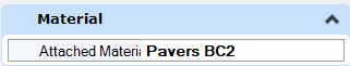
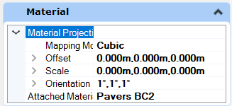
| public BentleyStatus DeleteMaterialAttachment( ) |
|---|
功能说明:
从元素中移除挂接的材质
输入:
无
输出:
BentleyStatus:若挂接在元素上的材质被移除则返回成功
示例:
private void DeleteMaterialAttachment()
{
#region Attach Material Attachment
DgnFile dgnFile = Session.Instance.GetActiveDgnFile();//获得当前激活的文件信息
DgnModel dgnModel = Session.Instance.GetActiveDgnModel();//获得当前激活的模型空间
MaterialTable matTbl = new MaterialTable(dgnFile);//创建材料表
matTbl.Name = "MyMaterialTable";//创建材料表名称
PaletteInfo[] palInfo = MaterialManager.GetPalettesInSearchPath("MS_MATERIAL");//从MS_MATERIAL的环境变量定义路径下读取材料图表
if (palInfo.Length < 1)//判断是否获取到材料图表
{
MessageCenter.Instance.ShowInfoMessage("Can't get palette", null, true);//输出错误信息
return;//返回
}
for (int i = 0; i < palInfo.Count(); i++)//遍历材料图表
{
if (palInfo[i].Name == "lightwidgets")//判断材料图表是否名为lightwidgets
{
matTbl.AddPalette(palInfo[i]);//添加材料图表至材料表
break;//跳出循环
}
else if (i == palInfo.Count() - 1)//若未找到名为lightwidgets的材料图表
{
MessageCenter.Instance.ShowErrorMessage("Can't find material lib named lightwidgets, please check",
"Can't find material lib named lightwidgets, please check",
true);//输出错误信息
}
}
MaterialManager.SetActiveTable(matTbl, dgnModel);//设置当前材料表为激活图表
MaterialManager.SaveTable(matTbl);//保存材料表
MaterialId id = new MaterialId("Pavers BC2");//查找名为Pavers BC2的材料
DPoint3d[] pos = { DPoint3d.Zero, new DPoint3d(10000, 0, 0), new DPoint3d(10000, 10000, 0) };//创建坐标数组
ShapeElement shape = new ShapeElement(Session.Instance.GetActiveDgnModel(), null, pos);//创建图形元素的实例
SurfaceOrSolidElement solid = SolidElement.CreateProjectionElement(Session.Instance.GetActiveDgnModel(), null, shape, new DPoint3d(1000, 0, 0),
new DVector3d(0, 0, 100000), DTransform3d.Identity, true);//创建拉伸实体元素
MaterialPropertiesExtension propertiesExtension = MaterialPropertiesExtension.GetAsMaterialPropertiesExtension(solid);//为拉伸实体元素设置材料属性
propertiesExtension.AddMaterialAttachment(id);//添加嵌入的材料信息
propertiesExtension.StoresAttachmentInfo(id);//保存拉伸实体元素的材料信息
propertiesExtension.AddToModel();//将拉伸实体写入模型
#endregion
DTransform3d dTransform = DTransform3d.FromTranslation(new DPoint3d(0,10*10000,0));//构建变换矩阵(该矩阵表示将元素将Y正方向平移十米)
TransformInfo trans = new TransformInfo(dTransform);//声明变换信息
propertiesExtension.ApplyTransform(trans);//对挂接了材质的拉伸实体元素应用变换
propertiesExtension.DeleteMaterialAttachment();//从元素中移除挂接的材质
propertiesExtension.AddToModel();//将拉伸实体写入模型
}
| public BentleyStatus DetachSubEntityMaterial( string[ ] subEntities ) |
|---|
功能说明:
从元素中的组成部分移除挂接的材质
输入:
string[ ] subEntities:挂接材质的元素组成部分
输出:
BentleyStatus:若挂接在元素上的材质被移除则返回成功
示例:
暂无
| public Material FindMaterial( LevelId level, uint colorIndex, DgnModelRef renderModelRef, bool useSymbologyOverride ) |
|---|
功能说明:
查询元素是否具有与其关联的材质。将根据材料赋予、挂接、覆盖等的优先级来确定元素的材质。仅当元素的文件保持加载状态并且材质未被其他调用方修改时,此方法才有效
输入:
LevelId level:对元素生效的图层。因为覆盖机制,他可能与元素的图层不同
uint colorIndex:对元素生效的颜色索引。因为覆盖机制,他可能与元素的图层不同
DgnModelRef renderModelRef:使用该材质的模型,用来保证与真实世界的比例一致
bool useSymbologyOverride:明确查询覆盖材质还是图层中的材质
输出:
Material:依附于元素上的材质
示例:
private void FindMaterialExample()
{
#region Create level with material
DgnFile dgnFile = Session.Instance.GetActiveDgnFile();//获得当前激活的dgn文件
DgnModel dgnModel = Session.Instance.GetActiveDgnModel();//获得当前激活的dgn模型
string levelName = "Level 1 :0";//声明字符串指代图层名称
FileLevelCache flc = dgnModel.GetFileLevelCache();//获得模型中的图层文件缓存
LevelHandle level = flc.GetLevelByName(levelName);//根据图层名称获得图层句柄
if (!level.IsValid)//判断图层是否有效(若图层无效在则为真)
{
EditLevelHandle elh = flc.CreateLevel(levelName);//声明名为levelName的图层
#region Create material
MaterialTable createdTable = new MaterialTable(dgnFile);//声明材料表
createdTable.Name = "Table1";//设置材料表名称
createdTable.Description = "Description1";//设置材料表描述信息
Material savedMaterial1 = new Material(dgnModel);//声明材料
savedMaterial1.Name = "Material5";//设置材料名称
PaletteInfo pInfo1 = savedMaterial1.GetPalette();//设置材料所在面板信息
pInfo1.Name = "SavedPalette";//设置材料所在面板名称
pInfo1.SetSource(dgnFile.GetDocument().GetMoniker());//设置面板源文件域
pInfo1.Type = PaletteInfo.PaletteType.Dgn;//设置面板类型
MaterialManager.SaveMaterial(null, savedMaterial1, dgnFile);//保存材料信息
Material savedMaterial2 = new Material(dgnModel);//声明材料
savedMaterial2.Name = "Material7";//设置材料名称
PaletteInfo pInfo2 = savedMaterial2.GetPalette();//设置材料所在面板信息
pInfo2.Name = "SavedPalette";//设置材料所在面板名称
pInfo2.SetSource(dgnFile.GetDocument().GetMoniker());//设置面板源文件域
pInfo2.Type = PaletteInfo.PaletteType.Dgn;//设置面板类型
MaterialManager.SaveMaterial(null, savedMaterial2, dgnFile);//保存材料信息
MaterialId materialId = new MaterialId("Material5");//声明材料ID
createdTable.AddAssignment(new MaterialAssignment(materialId, "Level 1", 0, createdTable.GetRenderDgn()));//将材料分配信息添加到表中
createdTable.AddAssignment(new MaterialAssignment(new MaterialId("Material7"), "Level 10", 4, createdTable.GetRenderDgn()));//将材料分配信息添加到表中
MaterialManager.SaveTable(createdTable);//保存材料表
flc.Write();//将文件写入缓存
#endregion
}
#endregion
#region Create solid
DPoint3d[] pos = { DPoint3d.Zero, new DPoint3d(10000, 0, 0), new DPoint3d(10000, 10000, 0) };//创建坐标数组
ShapeElement shape = new ShapeElement(Session.Instance.GetActiveDgnModel(), null, pos);//创建图形元素的实例
SurfaceOrSolidElement solid = SolidElement.CreateProjectionElement(Session.Instance.GetActiveDgnModel(), null, shape, new DPoint3d(1000, 0, 0),
new DVector3d(0, 0, 100000), DTransform3d.Identity, true);//创建拉伸实体元素
#endregion
ElementPropertiesSetter setter = new ElementPropertiesSetter();//声明元素属性赋值类
setter.SetLevel(flc.GetLevelByName(levelName).LevelId);//设置元素的图层
setter.Apply(solid);//对指定元素赋予属性
solid.AddToModel();//将拉伸实体元素添加到模型中
MaterialPropertiesExtension propertiesExtension = MaterialPropertiesExtension.GetAsMaterialPropertiesExtension(solid);//为拉伸实体元素设置材料属性
Material material = propertiesExtension.FindMaterial(flc.GetLevelByName(levelName).LevelId, 0, dgnModel, true);//获取指定元素上的材质
MessageBox.Show("The name of this material is " + material.Name, "The name of this material is " + material.Name);//在对话框中输出材质名称
}
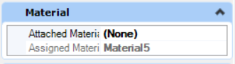
| public Material FindMaterialAttachment( DgnModelRef renderModelRef ) |
|---|
功能说明:
查询元素是否具有挂接的材质。由于材质赋予具有与元素关联的最高优先级,当材质以任何其他方式与元素赋予时不会执行查询。仅当元素的设计文件保持加载状态并且材质未被其他调用方修改时,此方法才有效
输入:
DgnModelRef renderModelRef:使用该材质的模型,用来保证与真实世界的比例一致
输出:
Material:挂接于元素上的材质
示例:
private void FindMaterialAttachmentExample()
{
#region Attach Material Attachment
DgnFile dgnFile = Session.Instance.GetActiveDgnFile();//获得当前激活的文件信息
DgnModel dgnModel = Session.Instance.GetActiveDgnModel();//获得当前激活的模型空间
MaterialTable matTbl = new MaterialTable(dgnFile);//创建材料表
matTbl.Name = "MyMaterialTable";//创建材料表名称
PaletteInfo[] palInfo = MaterialManager.GetPalettesInSearchPath("MS_MATERIAL");//从MS_MATERIAL的环境变量定义路径下读取材料图表
if (palInfo.Length < 1)//判断是否获取到材料图表
{
MessageCenter.Instance.ShowInfoMessage("Can't get palette", null, true);//输出错误信息
return;//返回
}
for (int i = 0; i < palInfo.Count(); i++)//遍历材料图表
{
if (palInfo[i].Name == "lightwidgets")//判断材料图表是否名为lightwidgets
{
matTbl.AddPalette(palInfo[i]);//添加材料图表至材料表
break;//跳出循环
}
else if (i == palInfo.Count() - 1)//若未找到名为lightwidgets的材料图表
{
MessageCenter.Instance.ShowErrorMessage("Can't find material lib named lightwidgets, please check",
"Can't find material lib named lightwidgets, please check",
true);//输出错误信息
}
}
MaterialManager.SetActiveTable(matTbl, dgnModel);//设置当前材料表为激活图表
MaterialManager.SaveTable(matTbl);//保存材料表
MaterialId id = new MaterialId("Pavers BC2");//查找名为Pavers BC2的材料
DPoint3d[] pos = { DPoint3d.Zero, new DPoint3d(10000, 0, 0), new DPoint3d(10000, 10000, 0) };//创建坐标数组
ShapeElement shape = new ShapeElement(Session.Instance.GetActiveDgnModel(), null, pos);//创建图形元素的实例
SurfaceOrSolidElement solid = SolidElement.CreateProjectionElement(Session.Instance.GetActiveDgnModel(), null, shape, new DPoint3d(1000, 0, 0),
new DVector3d(0, 0, 100000), DTransform3d.Identity, true);//创建拉伸实体元素
MaterialPropertiesExtension propertiesExtension = MaterialPropertiesExtension.GetAsMaterialPropertiesExtension(solid);//为拉伸实体元素设置材料属性
propertiesExtension.AddMaterialAttachment(id);//添加嵌入的材料信息
propertiesExtension.StoresAttachmentInfo(id);//保存拉伸实体元素的材料信息
propertiesExtension.AddToModel();//将拉伸实体写入模型
#endregion
Material material = propertiesExtension.FindMaterialAttachment(dgnModel);//获取指定元素上挂接的材质
MessageBox.Show("The name of this material is " + material.Name, "The name of this material is " + material.Name);//在对话框中输出材质名称
}
| public ProjectionAttachmentType FindMaterialProjection( ) |
|---|
功能说明:
获得挂接在该元素上的材质投影类型
输入:
无
输出:
ProjectionAttachmentType:获取到元素上的材质投影类型
示例:
private void FindMaterialProjectionExample()
{
DgnFile dgnFile = Session.Instance.GetActiveDgnFile();//获得当前激活的文件信息
DgnModel dgnModel = Session.Instance.GetActiveDgnModel();//获得当前激活的模型空间
MaterialTable matTbl = new MaterialTable(dgnFile);//创建材料表
matTbl.Name = "MyMaterialTable";//创建材料表名称
PaletteInfo[] palInfo = MaterialManager.GetPalettesInSearchPath("MS_MATERIAL");//从MS_MATERIAL的环境变量定义路径下读取材料图表
if (palInfo.Length < 1)//判断是否获取到材料图表
{
MessageCenter.Instance.ShowInfoMessage("Can't get palette", null, true);//输出错误信息
return;//返回
}
for (int i = 0; i < palInfo.Count(); i++)//遍历材料图表
{
if (palInfo[i].Name == "lightwidgets")//判断材料图表是否名为lightwidgets
{
matTbl.AddPalette(palInfo[i]);//添加材料图表至材料表
break;//跳出循环
}
else if (i == palInfo.Count() - 1)//若未找到名为lightwidgets的材料图表
{
MessageCenter.Instance.ShowErrorMessage("Can't find material lib named lightwidgets, please check",
"Can't find material lib named lightwidgets, please check",
true);//输出错误信息
}
}
MaterialManager.SetActiveTable(matTbl, dgnModel);//设置当前材料表为激活图表
MaterialManager.SaveTable(matTbl);//保存材料表
MaterialId id = new MaterialId("Pavers BC2");//查找名为Pavers BC2的材料
DPoint3d[] pos = { DPoint3d.Zero, new DPoint3d(10000, 0, 0), new DPoint3d(10000, 10000, 0) };//创建坐标数组
ShapeElement shape = new ShapeElement(Session.Instance.GetActiveDgnModel(), null, pos);//创建图形元素的实例
SurfaceOrSolidElement solid = SolidElement.CreateProjectionElement(Session.Instance.GetActiveDgnModel(), null, shape, new DPoint3d(1000, 0, 0),
new DVector3d(0, 0, 100000), DTransform3d.Identity, true);//创建拉伸实体元素
MaterialPropertiesExtension propertiesExtension = MaterialPropertiesExtension.GetAsMaterialPropertiesExtension(solid);//为拉伸实体元素设置材料属性
propertiesExtension.AddMaterialAttachment(id);//添加嵌入的材料信息
propertiesExtension.AddElementProjection(new DPoint3d(0, 0, 0), new DPoint3d(1, 1, 1), new DPoint3d(1, 1, 1), MapMode.Cubic, ProjectionVariant.CylindricalCapped);//添加元素投影信息
propertiesExtension.AddToModel();//将拉伸实体写入模型
ProjectionAttachmentType projectionType= propertiesExtension.FindMaterialProjection();//获得该元素上附加材质的投影类型
MessageBox.Show("The Projection Attachment Type of this material is " + projectionType.ToString(), "The Projection Attachment Type of this material is " + projectionType.ToString());//在对话框中输出该元素上附加材质的投影类型
}
| public static MaterialPropertiesExtension GetAsMaterialPropertiesExtension( DisplayableElement element ) |
|---|
功能说明:
将可视化元素转化为材料属性扩展元素
输入:
DisplayableElement element:可视化元素
输出:
MaterialPropertiesExtension:材料属性扩展元素
示例:
private void GetAsMaterialPropertiesExtensionExample2()
{
DgnFile dgnFile = Session.Instance.GetActiveDgnFile();//获得当前激活的文件信息
DgnModel dgnModel = Session.Instance.GetActiveDgnModel();//获得当前激活的模型空间
MaterialTable matTbl = new MaterialTable(dgnFile);//创建材料表
matTbl.Name = "MyMaterialTable";//创建材料表名称
PaletteInfo[] palInfo = MaterialManager.GetPalettesInSearchPath("MS_MATERIAL");//从MS_MATERIAL的环境变量定义路径下读取材料图表
if (palInfo.Length < 1)//判断是否获取到材料图表
{
MessageCenter.Instance.ShowInfoMessage("Can't get palette", null, true);//输出错误信息
return;//返回
}
for (int i = 0; i < palInfo.Count(); i++)//遍历材料图表
{
if (palInfo[i].Name == "lightwidgets")//判断材料图表是否名为lightwidgets
{
matTbl.AddPalette(palInfo[i]);//添加材料图表至材料表
break;//跳出循环
}
else if (i == palInfo.Count() - 1)//若未找到名为lightwidgets的材料图表
{
MessageCenter.Instance.ShowErrorMessage("Can't find material lib named lightwidgets, please check",
"Can't find material lib named lightwidgets, please check",
true);//输出错误信息
}
}
MaterialManager.SetActiveTable(matTbl, dgnModel);//设置当前材料表为激活图表
MaterialManager.SaveTable(matTbl);//保存材料表
MaterialId id = new MaterialId("Pavers BC2");//查找名为Pavers BC2的材料
DPoint3d[] pos = { DPoint3d.Zero, new DPoint3d(10000, 0, 0), new DPoint3d(10000, 10000, 0) };//创建坐标数组
ShapeElement shape = new ShapeElement(Session.Instance.GetActiveDgnModel(), null, pos);//创建图形元素的实例
SurfaceOrSolidElement solid = SolidElement.CreateProjectionElement(Session.Instance.GetActiveDgnModel(), null, shape, new DPoint3d(1000, 0, 0),
new DVector3d(0, 0, 100000), DTransform3d.Identity, true);//创建拉伸实体元素
MaterialPropertiesExtension propertiesExtension = MaterialPropertiesExtension.GetAsMaterialPropertiesExtension(solid);//为拉伸实体元素设置材料属性
propertiesExtension.AddMaterialAttachment(id);//添加嵌入的材料信息
propertiesExtension.AddToModel();//将拉伸实体写入模型
}
| public BentleyStatus GetMaterialProjectionParameters( ProjectionAttachmentType type, MapUnits units, out MaterialProjectionParameters parameters ) |
|---|
功能说明:
输出元素上材质的投影参数
输入:
ProjectionAttachmentType type:查找元素上挂接的材质投影类型
MapUnits units:投影的材质图层单位
out MaterialProjectionParameters parameters:(输出)挂接投影的计算参数结果
输出:
BentleyStatus:若元素上已附加投影并且成功获得参数结果
示例:
private void GetMaterialProjectionParametersExample()
{
DgnFile dgnFile = Session.Instance.GetActiveDgnFile();//获得当前激活的文件信息
DgnModel dgnModel = Session.Instance.GetActiveDgnModel();//获得当前激活的模型空间
MaterialTable matTbl = new MaterialTable(dgnFile);//创建材料表
matTbl.Name = "MyMaterialTable";//创建材料表名称
PaletteInfo[] palInfo = MaterialManager.GetPalettesInSearchPath("MS_MATERIAL");//从MS_MATERIAL的环境变量定义路径下读取材料图表
if (palInfo.Length < 1)//判断是否获取到材料图表
{
MessageCenter.Instance.ShowInfoMessage("Can't get palette", null, true);//输出错误信息
return;//返回
}
for (int i = 0; i < palInfo.Count(); i++)//遍历材料图表
{
if (palInfo[i].Name == "lightwidgets")//判断材料图表是否名为lightwidgets
{
matTbl.AddPalette(palInfo[i]);//添加材料图表至材料表
break;//跳出循环
}
else if (i == palInfo.Count() - 1)//若未找到名为lightwidgets的材料图表
{
MessageCenter.Instance.ShowErrorMessage("Can't find material lib named lightwidgets, please check",
"Can't find material lib named lightwidgets, please check",
true);//输出错误信息
}
}
MaterialManager.SetActiveTable(matTbl, dgnModel);//设置当前材料表为激活图表
MaterialManager.SaveTable(matTbl);//保存材料表
MaterialId id = new MaterialId("Pavers BC2");//查找名为Pavers BC2的材料
DPoint3d[] pos = { DPoint3d.Zero, new DPoint3d(10000, 0, 0), new DPoint3d(10000, 10000, 0) };//创建坐标数组
ShapeElement shape = new ShapeElement(Session.Instance.GetActiveDgnModel(), null, pos);//创建图形元素的实例
SurfaceOrSolidElement solid = SolidElement.CreateProjectionElement(Session.Instance.GetActiveDgnModel(), null, shape, new DPoint3d(1000, 0, 0),
new DVector3d(0, 0, 100000), DTransform3d.Identity, true);//创建拉伸实体元素
MaterialPropertiesExtension propertiesExtension = MaterialPropertiesExtension.GetAsMaterialPropertiesExtension(solid);//为拉伸实体元素设置材料属性
propertiesExtension.AddMaterialAttachment(id);//添加嵌入的材料信息
propertiesExtension.AddElementProjection(new DPoint3d(0, 0, 0), new DPoint3d(1, 1, 1), new DPoint3d(1, 1, 1), MapMode.Cubic, ProjectionVariant.CylindricalCapped);//添加元素投影信息
propertiesExtension.AddToModel();//将拉伸实体写入模型
propertiesExtension.GetMaterialProjectionParameters(ProjectionAttachmentType.Element,MapUnits.Meters,out MaterialProjectionParameters projectionParameters);//获得指定已附加材质信息的元素上材质的投影参数
MessageBox.Show("The scale of this projection in material is " + projectionParameters.Scale.ToString(),
"The scale of this projection in material is " + projectionParameters.Scale.ToString());//在对话框中输出该元素上附加材质的投影参数中缩放大小的信息
}
| public MaterialSubEntityPair[ ] GetSubEntityAttachments( ) |
|---|
功能说明:
获得该元素中材质子部件
输入:
无
输出:
MaterialSubEntityPair[ ]:材质子部件
示例:
暂无
| public bool HasSubEntityAttachments( ) |
|---|
功能说明:
判断该元素是否拥有多种材质
输入:
无
输出:
bool:若该元素拥有多种材质则返回真
示例:
private void HasSubEntityAttachmentsExample()
{
DgnFile dgnFile = Session.Instance.GetActiveDgnFile();//获得当前激活的文件信息
DgnModel dgnModel = Session.Instance.GetActiveDgnModel();//获得当前激活的模型空间
MaterialTable matTbl = new MaterialTable(dgnFile);//创建材料表
matTbl.Name = "MyMaterialTable";//创建材料表名称
PaletteInfo[] palInfo = MaterialManager.GetPalettesInSearchPath("MS_MATERIAL");//从MS_MATERIAL的环境变量定义路径下读取材料图表
if (palInfo.Length < 1)//判断是否获取到材料图表
{
MessageCenter.Instance.ShowInfoMessage("Can't get palette", null, true);//输出错误信息
return;//返回
}
for (int i = 0; i < palInfo.Count(); i++)//遍历材料图表
{
if (palInfo[i].Name == "lightwidgets")//判断材料图表是否名为lightwidgets
{
matTbl.AddPalette(palInfo[i]);//添加材料图表至材料表
break;//跳出循环
}
else if (i == palInfo.Count() - 1)//若未找到名为lightwidgets的材料图表
{
MessageCenter.Instance.ShowErrorMessage("Can't find material lib named lightwidgets, please check",
"Can't find material lib named lightwidgets, please check",
true);//输出错误信息
}
}
MaterialManager.SetActiveTable(matTbl, dgnModel);//设置当前材料表为激活图表
MaterialManager.SaveTable(matTbl);//保存材料表
MaterialId id = new MaterialId("Pavers BC2");//查找名为Pavers BC2的材料
DPoint3d[] pos = { DPoint3d.Zero, new DPoint3d(10000, 0, 0), new DPoint3d(10000, 10000, 0) };//创建坐标数组
ShapeElement shape = new ShapeElement(Session.Instance.GetActiveDgnModel(), null, pos);//创建图形元素的实例
SurfaceOrSolidElement solid = SolidElement.CreateProjectionElement(Session.Instance.GetActiveDgnModel(), null, shape, new DPoint3d(1000, 0, 0),
new DVector3d(0, 0, 100000), DTransform3d.Identity, true);//创建拉伸实体元素
MaterialPropertiesExtension propertiesExtension = MaterialPropertiesExtension.GetAsMaterialPropertiesExtension(solid);//为拉伸实体元素设置材料属性
propertiesExtension.AddMaterialAttachment(id);//添加嵌入的材料信息
propertiesExtension.AddToModel();//将拉伸实体写入模型
bool result= propertiesExtension.HasSubEntityAttachments();//判断该元素是否拥有多种材质
MessageBox.Show("The element has multiple materials that is " + result,
"The element has multiple materials that is " + result);//在对话框中输出该元素上是否拥有多种材质
}
| public BentleyStatus StoresAttachmentInfo( MaterialId id ) |
|---|
功能说明:
查询元素是否挂接了材质。可能存在的情况有元素上已挂接材质,但是挂接的材质不存在,如果存储的挂接材质是内部的,此方法将使用内部附件的ElementId填充传入的MaterialId以查找缺失的材料;如果存储的附件类型是挂接,则为缺失材质的名称
输入:
MaterialId id:储存材质信息的ID
输出:
BentleyStatus:若该元素中存储了挂接信息则返回成功
示例:
private void StoresAttachmentInfoExample()
{
DgnFile dgnFile = Session.Instance.GetActiveDgnFile();//获得当前激活的文件信息
DgnModel dgnModel = Session.Instance.GetActiveDgnModel();//获得当前激活的模型空间
MaterialTable matTbl = new MaterialTable(dgnFile);//创建材料表
matTbl.Name = "MyMaterialTable";//创建材料表名称
PaletteInfo[] palInfo = MaterialManager.GetPalettesInSearchPath("MS_MATERIAL");//从MS_MATERIAL的环境变量定义路径下读取材料图表
if (palInfo.Length < 1)//判断是否获取到材料图表
{
MessageCenter.Instance.ShowInfoMessage("Can't get palette", null, true);//输出错误信息
return;//返回
}
for (int i = 0; i < palInfo.Count(); i++)//遍历材料图表
{
if (palInfo[i].Name == "lightwidgets")//判断材料图表是否名为lightwidgets
{
matTbl.AddPalette(palInfo[i]);//添加材料图表至材料表
break;//跳出循环
}
else if (i == palInfo.Count() - 1)//若未找到名为lightwidgets的材料图表
{
MessageCenter.Instance.ShowErrorMessage("Can't find material lib named lightwidgets, please check",
"Can't find material lib named lightwidgets, please check",
true);//输出错误信息
}
}
MaterialManager.SetActiveTable(matTbl, dgnModel);//设置当前材料表为激活图表
MaterialManager.SaveTable(matTbl);//保存材料表
MaterialId id = new MaterialId("Pavers BC2");//查找名为Pavers BC2的材料
DPoint3d[] pos = { DPoint3d.Zero, new DPoint3d(10000, 0, 0), new DPoint3d(10000, 10000, 0) };//创建坐标数组
ShapeElement shape = new ShapeElement(Session.Instance.GetActiveDgnModel(), null, pos);//创建图形元素的实例
SurfaceOrSolidElement solid = SolidElement.CreateProjectionElement(Session.Instance.GetActiveDgnModel(), null, shape, new DPoint3d(1000, 0, 0),
new DVector3d(0, 0, 100000), DTransform3d.Identity, true);//创建拉伸实体元素
MaterialPropertiesExtension propertiesExtension = MaterialPropertiesExtension.GetAsMaterialPropertiesExtension(solid);//为拉伸实体元素设置材料属性
propertiesExtension.AddMaterialAttachment(id);//添加嵌入的材料信息
propertiesExtension.AddToModel();//将拉伸实体写入模型
BentleyStatus status= propertiesExtension.StoresAttachmentInfo(id);//查询元素是否挂接了指定材质
MessageBox.Show("The element store the attachment material named " + id.Name + " that is " + status,
"The element store the attachment material named " + id.Name + " that is " + status);//在对话框中输出该元素是否挂接了指定材质
}
| public bool SupportsSubEntityAttachments( ) |
|---|
功能说明:
查询元素是否具有附加多种材质的能力
输入:
无
输出:
bool:若该元素可同时附加多种材质则返回成功
示例:
private void SupportsSubEntityAttachmentsExample()
{
DgnFile dgnFile = Session.Instance.GetActiveDgnFile();//获得当前激活的文件信息
DgnModel dgnModel = Session.Instance.GetActiveDgnModel();//获得当前激活的模型空间
MaterialTable matTbl = new MaterialTable(dgnFile);//创建材料表
matTbl.Name = "MyMaterialTable";//创建材料表名称
PaletteInfo[] palInfo = MaterialManager.GetPalettesInSearchPath("MS_MATERIAL");//从MS_MATERIAL的环境变量定义路径下读取材料图表
if (palInfo.Length < 1)//判断是否获取到材料图表
{
MessageCenter.Instance.ShowInfoMessage("Can't get palette", null, true);//输出错误信息
return;//返回
}
for (int i = 0; i < palInfo.Count(); i++)//遍历材料图表
{
if (palInfo[i].Name == "lightwidgets")//判断材料图表是否名为lightwidgets
{
matTbl.AddPalette(palInfo[i]);//添加材料图表至材料表
break;//跳出循环
}
else if (i == palInfo.Count() - 1)//若未找到名为lightwidgets的材料图表
{
MessageCenter.Instance.ShowErrorMessage("Can't find material lib named lightwidgets, please check",
"Can't find material lib named lightwidgets, please check",
true);//输出错误信息
}
}
MaterialManager.SetActiveTable(matTbl, dgnModel);//设置当前材料表为激活图表
MaterialManager.SaveTable(matTbl);//保存材料表
MaterialId id = new MaterialId("Pavers BC2");//查找名为Pavers BC2的材料
DPoint3d[] pos = { DPoint3d.Zero, new DPoint3d(10000, 0, 0), new DPoint3d(10000, 10000, 0) };//创建坐标数组
ShapeElement shape = new ShapeElement(Session.Instance.GetActiveDgnModel(), null, pos);//创建图形元素的实例
SurfaceOrSolidElement solid = SolidElement.CreateProjectionElement(Session.Instance.GetActiveDgnModel(), null, shape, new DPoint3d(1000, 0, 0),
new DVector3d(0, 0, 100000), DTransform3d.Identity, true);//创建拉伸实体元素
MaterialPropertiesExtension propertiesExtension = MaterialPropertiesExtension.GetAsMaterialPropertiesExtension(solid);//为拉伸实体元素设置材料属性
propertiesExtension.AddMaterialAttachment(id);//添加嵌入的材料信息
propertiesExtension.AddToModel();//将拉伸实体写入模型
bool result= propertiesExtension.SupportsSubEntityAttachments();//查询元素是否具有附加多种材质的能力
MessageBox.Show("The element support subentity attachments that is " + result,
"The element support subentity attachments that is " + result);//在对话框中输出元素是否具有附加多种材质能力的结果
}
1.2.18 MeshHeaderElement
说明:
与MESH_HEADER结构相对应的MESH_HEADER_ELM类型的默认类。网格是一个复杂的元素,其组件包含定义网格类型的各种数据组
构造函数:
| public MeshHeaderElement( DgnModel dgnModel, Element templateElement, PolyfaceHeader meshData ) |
|---|
功能说明:
使用多面体几何的数据构造网格元素
输入:
DgnModel dgnModel:构造网格元素的模型
Element templateElement:元素模板,若为空则使用默认模板
PolyfaceHeader meshData:多面体几何
输出:
MeshHeaderElement:若网格元素被成功生成且几何范围信息计算成功
示例:
private void MeshHeaderElementExample()
{
DgnModel dgnModel = Session.Instance.GetActiveDgnModel();//获取当前的模型空间
#region create polyface
DPoint3d p1 = DPoint3d.Zero;//定义多面体端点坐标
DPoint3d p2 = new DPoint3d(10000, 0, 0);
DPoint3d p3 = new DPoint3d(0, 10000, 0);
DPoint3d p4 = new DPoint3d(0, 0, 10000);
IList<DPoint3d> pos = new List<DPoint3d>();//定义储存多面体坐标的列表
pos.Add(p1);//将多面体端点坐标添加到列表中
pos.Add(p2);
pos.Add(p3);
pos.Add(p4);
PolyfaceHeader polyface = new PolyfaceHeader();//定义多面体几何
polyface.Point = pos;//设置该多面体几何的端点集
polyface.ActivateVectorsForIndexing(polyface);//激活多面体几何中的数据与索引
List<int> indices = new List<int>();//定义索引列表
indices.Add(1); indices.Add(2); indices.Add(3); //将索引号添加到列表中
polyface.AddIndexedFacet(indices, null, null, indices);//添加索引信息到多面体几何中
indices.Clear();//清空索引列表
indices.Add(1); indices.Add(2); indices.Add(4);//继续将索引号添加到列表中
polyface.AddIndexedFacet(indices, null, null, indices);
indices.Clear();
indices.Add(2); indices.Add(3); indices.Add(4);
polyface.AddIndexedFacet(indices, null, null, indices);
indices.Clear();
indices.Add(1); indices.Add(3); indices.Add(4);
polyface.AddIndexedFacet(indices, null, null, indices);
#endregion
MeshHeaderElement mesh = new MeshHeaderElement(dgnModel, null, polyface);//定义使用多面体几何网格元素
mesh.AddToModel();//将网格元素添加到模型空间中
}
方法:
| public MeshEdit AsMeshEdit( ) |
|---|
功能说明:
修改表示网格的元素
输入:
无
输出:
MeshEdit:可修改的网格元素
示例:
private void AsMeshEditExample()
{
DgnModel dgnModel = Session.Instance.GetActiveDgnModel();//获取当前的模型空间
#region create polyface
DPoint3d p1 = DPoint3d.Zero;//定义多面体端点坐标
DPoint3d p2 = new DPoint3d(10000, 0, 0);
DPoint3d p3 = new DPoint3d(0, 10000, 0);
DPoint3d p4 = new DPoint3d(0, 0, 10000);
IList<DPoint3d> pos = new List<DPoint3d>();//定义储存多面体坐标的列表
pos.Add(p1);//将多面体端点坐标添加到列表中
pos.Add(p2);
pos.Add(p3);
pos.Add(p4);
PolyfaceHeader polyface = new PolyfaceHeader();//定义多面体几何
polyface.Point = pos;//设置该多面体几何的端点集
polyface.ActivateVectorsForIndexing(polyface);//激活多面体几何中的数据与索引
List<int> indices = new List<int>();//定义索引列表
indices.Add(1); indices.Add(2); indices.Add(3); //将索引号添加到列表中
polyface.AddIndexedFacet(indices, null, null, indices);//添加索引信息到多面体几何中
indices.Clear();//清空索引列表
indices.Add(1); indices.Add(2); indices.Add(4);//继续将索引号添加到列表中
polyface.AddIndexedFacet(indices, null, null, indices);
indices.Clear();
indices.Add(2); indices.Add(3); indices.Add(4);
polyface.AddIndexedFacet(indices, null, null, indices);
indices.Clear();
indices.Add(1); indices.Add(3); indices.Add(4);
polyface.AddIndexedFacet(indices, null, null, indices);
#endregion
MeshHeaderElement mesh = new MeshHeaderElement(dgnModel, null, polyface);//定义使用多面体几何网格元素
mesh.AddToModel();//将网格元素添加到模型空间中
MeshEdit meshEdit= mesh.AsMeshEdit();//获得对应可编辑的由多面体几何构成的网格元素
#region create polyface
p1 = new DPoint3d(10000, 10000, 0);//定义多面体端点坐标
p2 = new DPoint3d(0,10000, 0);
p3 = new DPoint3d(10000, 10000, 10000);
p4 = new DPoint3d(10000, 0, 0);
pos = new List<DPoint3d>();//定义储存多面体坐标的列表
pos.Add(p1);//将多面体端点坐标添加到列表中
pos.Add(p2);
pos.Add(p3);
pos.Add(p4);
PolyfaceHeader polyface2 = new PolyfaceHeader();//定义多面体几何
polyface2.Point = pos;//设置该多面体几何的端点集
polyface2.ActivateVectorsForIndexing(polyface2);//激活多面体几何中的数据与索引
indices = new List<int>();//定义索引列表
indices.Add(1); indices.Add(2); indices.Add(3); //将索引号添加到列表中
polyface2.AddIndexedFacet(indices, null, null, indices);//添加索引信息到多面体几何中
indices.Clear();//清空索引列表
indices.Add(1); indices.Add(2); indices.Add(4);//继续将索引号添加到列表中
polyface2.AddIndexedFacet(indices, null, null, indices);
indices.Clear();
indices.Add(2); indices.Add(3); indices.Add(4);
polyface2.AddIndexedFacet(indices, null, null, indices);
indices.Clear();
indices.Add(1); indices.Add(3); indices.Add(4);
polyface2.AddIndexedFacet(indices, null, null, indices);
#endregion
meshEdit.SetMeshData(polyface2);//修改网格元素的多面体几何
meshEdit.AddToModel();//将修改后的网格元素写入模型
}
| public PolyfaceHeader GetMeshData( ) |
|---|
功能说明:
判断该元素是否是由多面体几何构成的网格元素,若是则返回网格数据
输入:
无
输出:
PolyfaceHeader:若有效则返回网格数据
private void GetMeshDataExample()
{
DgnModel dgnModel = Session.Instance.GetActiveDgnModel();//获取当前的模型空间
#region create polyface
DPoint3d p1 = DPoint3d.Zero;//定义多面体端点坐标
DPoint3d p2 = new DPoint3d(10000, 0, 0);
DPoint3d p3 = new DPoint3d(0, 10000, 0);
DPoint3d p4 = new DPoint3d(0, 0, 10000);
IList<DPoint3d> pos = new List<DPoint3d>();//定义储存多面体坐标的列表
pos.Add(p1);//将多面体端点坐标添加到列表中
pos.Add(p2);
pos.Add(p3);
pos.Add(p4);
PolyfaceHeader polyface = new PolyfaceHeader();//定义多面体几何
polyface.Point = pos;//设置该多面体几何的端点集
polyface.ActivateVectorsForIndexing(polyface);//激活多面体几何中的数据与索引
List<int> indices = new List<int>();//定义索引列表
indices.Add(1); indices.Add(2); indices.Add(3); //将索引号添加到列表中
polyface.AddIndexedFacet(indices, null, null, indices);//添加索引信息到多面体几何中
indices.Clear();//清空索引列表
indices.Add(1); indices.Add(2); indices.Add(4);//继续将索引号添加到列表中
polyface.AddIndexedFacet(indices, null, null, indices);
indices.Clear();
indices.Add(2); indices.Add(3); indices.Add(4);
polyface.AddIndexedFacet(indices, null, null, indices);
indices.Clear();
indices.Add(1); indices.Add(3); indices.Add(4);
polyface.AddIndexedFacet(indices, null, null, indices);
#endregion
MeshHeaderElement mesh = new MeshHeaderElement(dgnModel, null, polyface);//定义使用多面体几何网格元素
mesh.AddToModel();//将网格元素添加到模型空间中
PolyfaceHeader polyfaceInMesh= mesh.GetMeshData();//获得构成网格元素的多面体几何
uint facetCount= polyfaceInMesh.FacetCount;//获得多面体几何的面片数
MessageBox.Show("The facet number of this mesh is " + facetCount,
"The facet number of this mesh is " + facetCount);//在对话框中输出该网格元素的面片数
}
| public BentleyStatus SetMeshData( PolyfaceHeader meshData ) |
|---|
功能说明:
从网格数据(多面体几何)中更新元素
输入:
PolyfaceHeader meshData:网格数据(多面体几何)
输出:
BentleyStatus:若元素被更新则返回成功
示例:
private void SetMeshDataExample()
{
DgnModel dgnModel = Session.Instance.GetActiveDgnModel();//获取当前的模型空间
#region create polyface
DPoint3d p1 = DPoint3d.Zero;//定义多面体端点坐标
DPoint3d p2 = new DPoint3d(10000, 0, 0);
DPoint3d p3 = new DPoint3d(0, 10000, 0);
DPoint3d p4 = new DPoint3d(0, 0, 10000);
IList<DPoint3d> pos = new List<DPoint3d>();//定义储存多面体坐标的列表
pos.Add(p1);//将多面体端点坐标添加到列表中
pos.Add(p2);
pos.Add(p3);
pos.Add(p4);
PolyfaceHeader polyface = new PolyfaceHeader();//定义多面体几何
polyface.Point = pos;//设置该多面体几何的端点集
polyface.ActivateVectorsForIndexing(polyface);//激活多面体几何中的数据与索引
List<int> indices = new List<int>();//定义索引列表
indices.Add(1); indices.Add(2); indices.Add(3); //将索引号添加到列表中
polyface.AddIndexedFacet(indices, null, null, indices);//添加索引信息到多面体几何中
indices.Clear();//清空索引列表
indices.Add(1); indices.Add(2); indices.Add(4);//继续将索引号添加到列表中
polyface.AddIndexedFacet(indices, null, null, indices);
indices.Clear();
indices.Add(2); indices.Add(3); indices.Add(4);
polyface.AddIndexedFacet(indices, null, null, indices);
indices.Clear();
indices.Add(1); indices.Add(3); indices.Add(4);
polyface.AddIndexedFacet(indices, null, null, indices);
#endregion
MeshHeaderElement mesh = new MeshHeaderElement(dgnModel, null, polyface);//定义使用多面体几何网格元素
mesh.AddToModel();//将网格元素添加到模型空间中
MeshEdit meshEdit = mesh.AsMeshEdit();
#region create polyface
p1 = new DPoint3d(10000, 10000, 0);//定义多面体端点坐标
p2 = new DPoint3d(0, 10000, 0);
p3 = new DPoint3d(10000, 10000, 10000);
p4 = new DPoint3d(10000, 0, 0);
pos = new List<DPoint3d>();//定义储存多面体坐标的列表
pos.Add(p1);//将多面体端点坐标添加到列表中
pos.Add(p2);
pos.Add(p3);
pos.Add(p4);
PolyfaceHeader polyface2 = new PolyfaceHeader();//定义多面体几何
polyface2.Point = pos;//设置该多面体几何的端点集
polyface2.ActivateVectorsForIndexing(polyface2);//激活多面体几何中的数据与索引
indices = new List<int>();//定义索引列表
indices.Add(1); indices.Add(2); indices.Add(3); //将索引号添加到列表中
polyface2.AddIndexedFacet(indices, null, null, indices);//添加索引信息到多面体几何中
indices.Clear();//清空索引列表
indices.Add(1); indices.Add(2); indices.Add(4);//继续将索引号添加到列表中
polyface2.AddIndexedFacet(indices, null, null, indices);
indices.Clear();
indices.Add(2); indices.Add(3); indices.Add(4);
polyface2.AddIndexedFacet(indices, null, null, indices);
indices.Clear();
indices.Add(1); indices.Add(3); indices.Add(4);
polyface2.AddIndexedFacet(indices, null, null, indices);
#endregion
mesh.SetMeshData(polyface2);//更新网格元素的多面体几何
mesh.AddToModel();//将更新后的网格元素写入模型
}
1.2.19 MeshQuery
说明:
用于查询几何信息的由多面体几何构成的网格元素
方法:
| public static MeshQuery GetAsMeshQuery( Element element ) |
|---|
功能说明:
查询一个由多面体几何构成网格元素的几何信息
输入:
Element element:目标元素
输出:
MeshQuery:用于查询几何信息的由多面体几何构成的网格元素
示例:
private void GetAsMeshQueryExample()
{
DgnModel dgnModel = Session.Instance.GetActiveDgnModel();//获取当前的模型空间
#region create polyface
DPoint3d p1 = DPoint3d.Zero;//定义多面体端点坐标
DPoint3d p2 = new DPoint3d(10000, 0, 0);
DPoint3d p3 = new DPoint3d(0, 10000, 0);
DPoint3d p4 = new DPoint3d(0, 0, 10000);
IList<DPoint3d> pos = new List<DPoint3d>();//定义储存多面体坐标的列表
pos.Add(p1);//将多面体端点坐标添加到列表中
pos.Add(p2);
pos.Add(p3);
pos.Add(p4);
PolyfaceHeader polyface = new PolyfaceHeader();//定义多面体几何
polyface.Point = pos;//设置该多面体几何的端点集
polyface.ActivateVectorsForIndexing(polyface);//激活多面体几何中的数据与索引
List<int> indices = new List<int>();//定义索引列表
indices.Add(1); indices.Add(2); indices.Add(3); //将索引号添加到列表中
polyface.AddIndexedFacet(indices, null, null, indices);//添加索引信息到多面体几何中
indices.Clear();//清空索引列表
indices.Add(1); indices.Add(2); indices.Add(4);//继续将索引号添加到列表中
polyface.AddIndexedFacet(indices, null, null, indices);
indices.Clear();
indices.Add(2); indices.Add(3); indices.Add(4);
polyface.AddIndexedFacet(indices, null, null, indices);
indices.Clear();
indices.Add(1); indices.Add(3); indices.Add(4);
polyface.AddIndexedFacet(indices, null, null, indices);
#endregion
MeshHeaderElement mesh = new MeshHeaderElement(dgnModel, null, polyface);//定义使用多面体几何网格元素
mesh.AddToModel();//将网格元素添加到模型空间中
MeshQuery query= MeshQuery.GetAsMeshQuery(mesh);//查询一个由多面体几何构成网格元素的几何信息
PolyfaceHeader polyfaceInMesh = query.GetMeshData();//获得构成网格元素的多面体几何
uint facetCount = polyfaceInMesh.FacetCount;//获得多面体几何的面片数
MessageBox.Show("The facet number of this mesh is " + facetCount,
"The facet number of this mesh is " + facetCount);//在对话框中输出该网格元素的面片数
}
| public PolyfaceHeader GetMeshData( ) |
|---|
功能说明:
判断该元素是否为由多面体几何构成的网格元素,若是则返回多面体几何数据
输入:
无
输出:
PolyfaceHeader:构成网格元素的多面体几何
示例:
private void GetMeshDataExample2()
{
DgnModel dgnModel = Session.Instance.GetActiveDgnModel();//获取当前的模型空间
#region create polyface
DPoint3d p1 = DPoint3d.Zero;//定义多面体端点坐标
DPoint3d p2 = new DPoint3d(10000, 0, 0);
DPoint3d p3 = new DPoint3d(0, 10000, 0);
DPoint3d p4 = new DPoint3d(0, 0, 10000);
IList<DPoint3d> pos = new List<DPoint3d>();//定义储存多面体坐标的列表
pos.Add(p1);//将多面体端点坐标添加到列表中
pos.Add(p2);
pos.Add(p3);
pos.Add(p4);
PolyfaceHeader polyface = new PolyfaceHeader();//定义多面体几何
polyface.Point = pos;//设置该多面体几何的端点集
polyface.ActivateVectorsForIndexing(polyface);//激活多面体几何中的数据与索引
List<int> indices = new List<int>();//定义索引列表
indices.Add(1); indices.Add(2); indices.Add(3); //将索引号添加到列表中
polyface.AddIndexedFacet(indices, null, null, indices);//添加索引信息到多面体几何中
indices.Clear();//清空索引列表
indices.Add(1); indices.Add(2); indices.Add(4);//继续将索引号添加到列表中
polyface.AddIndexedFacet(indices, null, null, indices);
indices.Clear();
indices.Add(2); indices.Add(3); indices.Add(4);
polyface.AddIndexedFacet(indices, null, null, indices);
indices.Clear();
indices.Add(1); indices.Add(3); indices.Add(4);
polyface.AddIndexedFacet(indices, null, null, indices);
#endregion
MeshHeaderElement mesh = new MeshHeaderElement(dgnModel, null, polyface);//定义使用多面体几何网格元素
mesh.AddToModel();//将网格元素添加到模型空间中
MeshQuery query = MeshQuery.GetAsMeshQuery(mesh);//查询一个由多面体几何构成网格元素的几何信息
PolyfaceHeader polyfaceInMesh = query.GetMeshData();//获得构成网格元素的多面体几何
uint facetCount = polyfaceInMesh.FacetCount;//获得多面体几何的面片数
MessageBox.Show("The facet number of this mesh is " + facetCount,
"The facet number of this mesh is " + facetCount);//在对话框中输出该网格元素的面片数
}
1.2.19.1 MeshEdit
说明:
可修改的网格元素
方法:
| public static MeshEdit GetAsMeshEdit( Element element ) |
|---|
功能说明:
判断该元素是否是由多面体几何构成的网格元素,若是则返回网格数据
输入:
Element element:目标元素
输出:
MeshEdit:由多面体几何构成的网格元素的网格数据
private void GetAsMeshEditExample()
{
DgnModel dgnModel = Session.Instance.GetActiveDgnModel();//获取当前的模型空间
#region create polyface
DPoint3d p1 = DPoint3d.Zero;//定义多面体端点坐标
DPoint3d p2 = new DPoint3d(10000, 0, 0);
DPoint3d p3 = new DPoint3d(0, 10000, 0);
DPoint3d p4 = new DPoint3d(0, 0, 10000);
IList<DPoint3d> pos = new List<DPoint3d>();//定义储存多面体坐标的列表
pos.Add(p1);//将多面体端点坐标添加到列表中
pos.Add(p2);
pos.Add(p3);
pos.Add(p4);
PolyfaceHeader polyface = new PolyfaceHeader();//定义多面体几何
polyface.Point = pos;//设置该多面体几何的端点集
polyface.ActivateVectorsForIndexing(polyface);//激活多面体几何中的数据与索引
List<int> indices = new List<int>();//定义索引列表
indices.Add(1); indices.Add(2); indices.Add(3); //将索引号添加到列表中
polyface.AddIndexedFacet(indices, null, null, indices);//添加索引信息到多面体几何中
indices.Clear();//清空索引列表
indices.Add(1); indices.Add(2); indices.Add(4);//继续将索引号添加到列表中
polyface.AddIndexedFacet(indices, null, null, indices);
indices.Clear();
indices.Add(2); indices.Add(3); indices.Add(4);
polyface.AddIndexedFacet(indices, null, null, indices);
indices.Clear();
indices.Add(1); indices.Add(3); indices.Add(4);
polyface.AddIndexedFacet(indices, null, null, indices);
#endregion
MeshHeaderElement mesh = new MeshHeaderElement(dgnModel, null, polyface);//定义使用多面体几何网格元素
mesh.AddToModel();//将网格元素添加到模型空间中
MeshEdit meshEdit = MeshEdit.GetAsMeshEdit(mesh);//判断该元素是否是由多面体几何构成的网格元素,若是则返回网格数据
#region create polyface
p1 = new DPoint3d(10000, 10000, 0);//定义多面体端点坐标
p2 = new DPoint3d(0, 10000, 0);
p3 = new DPoint3d(10000, 10000, 10000);
p4 = new DPoint3d(10000, 0, 0);
pos = new List<DPoint3d>();//定义储存多面体坐标的列表
pos.Add(p1);//将多面体端点坐标添加到列表中
pos.Add(p2);
pos.Add(p3);
pos.Add(p4);
PolyfaceHeader polyface2 = new PolyfaceHeader();//定义多面体几何
polyface2.Point = pos;//设置该多面体几何的端点集
polyface2.ActivateVectorsForIndexing(polyface2);//激活多面体几何中的数据与索引
indices = new List<int>();//定义索引列表
indices.Add(1); indices.Add(2); indices.Add(3); //将索引号添加到列表中
polyface2.AddIndexedFacet(indices, null, null, indices);//添加索引信息到多面体几何中
indices.Clear();//清空索引列表
indices.Add(1); indices.Add(2); indices.Add(4);//继续将索引号添加到列表中
polyface2.AddIndexedFacet(indices, null, null, indices);
indices.Clear();
indices.Add(2); indices.Add(3); indices.Add(4);
polyface2.AddIndexedFacet(indices, null, null, indices);
indices.Clear();
indices.Add(1); indices.Add(3); indices.Add(4);
polyface2.AddIndexedFacet(indices, null, null, indices);
#endregion
meshEdit.SetMeshData(polyface2);//修改网格元素的多面体几何
meshEdit.AddToModel();//将修改后的网格元素写入模型
}
| public BentleyStatus SetMeshData( PolyfaceHeader meshData ) |
|---|
功能说明:
更新网格数据
输入:
PolyfaceHeader meshData:用于构造网格元素的多面体几何
输出:
BentleyStatus:若元素被更新则返回成功
示例:
private void SetMeshDataExample2()
{
DgnModel dgnModel = Session.Instance.GetActiveDgnModel();//获取当前的模型空间
#region create polyface
DPoint3d p1 = DPoint3d.Zero;//定义多面体端点坐标
DPoint3d p2 = new DPoint3d(10000, 0, 0);
DPoint3d p3 = new DPoint3d(0, 10000, 0);
DPoint3d p4 = new DPoint3d(0, 0, 10000);
IList<DPoint3d> pos = new List<DPoint3d>();//定义储存多面体坐标的列表
pos.Add(p1);//将多面体端点坐标添加到列表中
pos.Add(p2);
pos.Add(p3);
pos.Add(p4);
PolyfaceHeader polyface = new PolyfaceHeader();//定义多面体几何
polyface.Point = pos;//设置该多面体几何的端点集
polyface.ActivateVectorsForIndexing(polyface);//激活多面体几何中的数据与索引
List<int> indices = new List<int>();//定义索引列表
indices.Add(1); indices.Add(2); indices.Add(3); //将索引号添加到列表中
polyface.AddIndexedFacet(indices, null, null, indices);//添加索引信息到多面体几何中
indices.Clear();//清空索引列表
indices.Add(1); indices.Add(2); indices.Add(4);//继续将索引号添加到列表中
polyface.AddIndexedFacet(indices, null, null, indices);
indices.Clear();
indices.Add(2); indices.Add(3); indices.Add(4);
polyface.AddIndexedFacet(indices, null, null, indices);
indices.Clear();
indices.Add(1); indices.Add(3); indices.Add(4);
polyface.AddIndexedFacet(indices, null, null, indices);
#endregion
MeshHeaderElement mesh = new MeshHeaderElement(dgnModel, null, polyface);//定义使用多面体几何网格元素
mesh.AddToModel();//将网格元素添加到模型空间中
MeshEdit meshEdit = MeshEdit.GetAsMeshEdit(mesh);//判断该元素是否是由多面体几何构成的网格元素,若是则返回网格数据
#region create polyface
p1 = new DPoint3d(10000, 10000, 0);//定义多面体端点坐标
p2 = new DPoint3d(0, 10000, 0);
p3 = new DPoint3d(10000, 10000, 10000);
p4 = new DPoint3d(10000, 0, 0);
pos = new List<DPoint3d>();//定义储存多面体坐标的列表
pos.Add(p1);//将多面体端点坐标添加到列表中
pos.Add(p2);
pos.Add(p3);
pos.Add(p4);
PolyfaceHeader polyface2 = new PolyfaceHeader();//定义多面体几何
polyface2.Point = pos;//设置该多面体几何的端点集
polyface2.ActivateVectorsForIndexing(polyface2);//激活多面体几何中的数据与索引
indices = new List<int>();//定义索引列表
indices.Add(1); indices.Add(2); indices.Add(3); //将索引号添加到列表中
polyface2.AddIndexedFacet(indices, null, null, indices);//添加索引信息到多面体几何中
indices.Clear();//清空索引列表
indices.Add(1); indices.Add(2); indices.Add(4);//继续将索引号添加到列表中
polyface2.AddIndexedFacet(indices, null, null, indices);
indices.Clear();
indices.Add(2); indices.Add(3); indices.Add(4);
polyface2.AddIndexedFacet(indices, null, null, indices);
indices.Clear();
indices.Add(1); indices.Add(3); indices.Add(4);
polyface2.AddIndexedFacet(indices, null, null, indices);
#endregion
meshEdit.SetMeshData(polyface2);//修改网格元素的多面体几何
meshEdit.AddToModel();//将修改后的网格元素写入模型
}
1.2.20 MultilineElement
说明:
多线元素结构的MULTILINE_ELM默认类型句柄
方法:
| public bool AddGradientFill( GradientSymbology symbology ) |
|---|
功能说明:
为支持的多线元素添加渐变填充
输入:
GradientSymbology symbology:渐变填充设置
输出:
bool:若元素被更新则返回成功
示例:
暂无
| public bool AddPattern( PatternParams parameters, DwgHatchDefLine[] hatchDefLines, int index ) |
|---|
功能说明:
为支持的多线元素添加图案或面积填充
输入:
PatternParams parameters:图案设置
DwgHatchDefLine[] hatchDefLines:DWG类型填充设置。注意:必须使用params.GetDwgHatchDef( ).nDefLines设置计数
int index:图案索引(仅在多线中生效)
输出:
bool:若元素被更新则返回真
示例:
private void AddPatternExample8()
{
DgnModel dgnModel = Session.Instance.GetActiveDgnModel();//获取当前的模型空间
DgnFile dgnFile = Session.Instance.GetActiveDgnFile();//获取当前模型所属文件
MultilineStyle lineStyle = new MultilineStyle("testMultiline", dgnFile);//定义多线元素样式
MultilineProfile profile1 = new MultilineProfile();//定义多线轮廓
profile1.Distance = 0;//设置轮廓偏移基点
profile1.UseLinestyle = true;//设置轮廓是否使用线样式
profile1.Linestyle = 1;//设置轮廓线样式
lineStyle.InsertProfile(profile1, 0);//将轮廓信息写入多线样式中
MultilineProfile profile2 = new MultilineProfile();//定义多线轮廓
profile2.Distance = -10000;//设置轮廓偏移基点
lineStyle.InsertProfile(profile2, 1);//将轮廓信息写入多线样式中
DVector3d vector = DVector3d.UnitZ;//设置多线法线方向向量
DPoint3d p1 = DPoint3d.Zero;//设置多线轨迹控制点
DPoint3d p2 = new DPoint3d(100000, 0, 0);
DPoint3d p3 = new DPoint3d(200000, 200000, 0);
DPoint3d[] pos = { p1, p2, p3 };//定义轨迹点数组
MultilineElement multiline = MultilineElement.CreateMultilineElement(dgnModel, null, lineStyle, 1, vector, pos);
/*
* 定义多线元素
* dgnModel:写入多线元素的模型空间
* templateElement:元素模板
* mlineStyle:多线样式
* styleScale:样式缩放比例
* normal:多线法线方向向量
* points:轨迹点数组
*/
PatternParams param = new PatternParams();//初始化模式定义
param.HoleStyle = PatternParamsHoleStyleType.Normal;//设置孔洞样式为普通
param.Color = 5;//设置颜色为紫色(索引为5)
param.PrimarySpacing = 10;//设置线段间隔距离为10
DwgHatchDefLine defLine = new DwgHatchDefLine();//初始化DWG填充定义
DwgHatchDefLine[] defLines = { defLine };//将DWG填充定义放入其数组中
multiline.AddPattern(param, defLines, 0);//为多线元素添加图案填充
multiline.AddToModel();//将多线元素写入模型空间
}
| public bool AddSolidFill( uint fillColor, bool alwaysFilled ) |
|---|
功能说明:
为支持的多线元素添加实体填充
输入:
uint fillColor:填充颜色索引,当使用颜色与边界颜色一致时可输入null
bool alwaysFilled:是否遵守“填充视图”属性,若为每个视图填充输入null
输出:
bool:当若元素被更新则返回真
示例:
private void AddSolidFillExample8()
{
DgnModel dgnModel = Session.Instance.GetActiveDgnModel();//获取当前的模型空间
DgnFile dgnFile = Session.Instance.GetActiveDgnFile();//获取当前模型所属文件
MultilineStyle lineStyle = new MultilineStyle("testMultiline", dgnFile);//定义多线元素样式
MultilineProfile profile1 = new MultilineProfile();//定义多线轮廓
profile1.Distance = 0;//设置轮廓偏移基点
profile1.UseLinestyle = true;//设置轮廓是否使用线样式
profile1.Linestyle = 1;//设置轮廓线样式
lineStyle.InsertProfile(profile1, 0);//将轮廓信息写入多线样式中
MultilineProfile profile2 = new MultilineProfile();//定义多线轮廓
profile2.Distance = -10000;//设置轮廓偏移基点
lineStyle.InsertProfile(profile2, 1);//将轮廓信息写入多线样式中
DVector3d vector = DVector3d.UnitZ;//设置多线法线方向向量
DPoint3d p1 = DPoint3d.Zero;//设置多线轨迹控制点
DPoint3d p2 = new DPoint3d(100000, 0, 0);
DPoint3d p3 = new DPoint3d(200000, 200000, 0);
DPoint3d[] pos = { p1, p2, p3 };//定义轨迹点数组
MultilineElement multiline = MultilineElement.CreateMultilineElement(dgnModel, null, lineStyle, 1, vector, pos);
/*
* 定义多线元素
* dgnModel:写入多线元素的模型空间
* templateElement:元素模板
* mlineStyle:多线样式
* styleScale:样式缩放比例
* normal:多线法线方向向量
* points:轨迹点数组
*/
multiline.AddSolidFill(4,true);//为多线元素添加实体填充
multiline.AddToModel();//将多线元素写入模型空间
}
| public BentleyStatus ApplyStyle( MultilineStyle mlineStyle, double styleScale ) |
|---|
功能说明:
对多线元素应用多线样式
输入:
MultilineStyle mlineStyle:多线样式
double styleScale:多线样式缩放比例
输出:
BentleyStatus:当多线元素的样式被更新则返回成功
示例:
private void ApplyStyleExample()
{
#region Create MultilineElement
DgnModel dgnModel = Session.Instance.GetActiveDgnModel();//获取当前的模型空间
DgnFile dgnFile = Session.Instance.GetActiveDgnFile();//获取当前模型所属文件
MultilineStyle lineStyle = new MultilineStyle("testMultiline", dgnFile);//定义多线元素样式
MultilineProfile profile1 = new MultilineProfile();//定义多线轮廓
profile1.Distance = 0;//设置轮廓偏移基点
profile1.UseLinestyle = true;//设置轮廓是否使用线样式
profile1.Linestyle = 1;//设置轮廓线样式
lineStyle.InsertProfile(profile1, 0);//将轮廓信息写入多线样式中
MultilineProfile profile2 = new MultilineProfile();//定义多线轮廓
profile2.Distance = -10000;//设置轮廓偏移基点
lineStyle.InsertProfile(profile2, 1);//将轮廓信息写入多线样式中
DVector3d vector = DVector3d.UnitZ;//设置多线法线方向向量
DPoint3d p1 = DPoint3d.Zero;//设置多线轨迹控制点
DPoint3d p2 = new DPoint3d(100000, 0, 0);
DPoint3d p3 = new DPoint3d(200000, 200000, 0);
DPoint3d[] pos = { p1, p2, p3 };//定义轨迹点数组
MultilineElement multiline = MultilineElement.CreateMultilineElement(dgnModel, null, lineStyle, 1, vector, pos);
/*
* 定义多线元素
* dgnModel:写入多线元素的模型空间
* templateElement:元素模板
* mlineStyle:多线样式
* styleScale:样式缩放比例
* normal:多线法线方向向量
* points:轨迹点数组
*/
multiline.AddToModel();//将多线元素写入模型空间
#endregion
MultilineStyle lineStyle2 = new MultilineStyle("testMultiline", dgnFile);//定义多线元素样式
MultilineProfile profile3 = new MultilineProfile();//定义多线轮廓
profile3.Distance = 0;//设置轮廓偏移基点
profile3.UseLinestyle = true;//设置轮廓是否使用线样式
profile3.Linestyle = 1;//设置轮廓线样式
lineStyle2.InsertProfile(profile3, 0);//将轮廓信息写入多线样式中
MultilineProfile profile4 = new MultilineProfile();//定义多线轮廓
profile4.Distance = -10000;//设置轮廓偏移基点
lineStyle2.InsertProfile(profile4, 1);//将轮廓信息写入多线样式中
multiline.ApplyStyle(lineStyle2,2);//对多线元素应用多线样式 这里将缩放比例设为2,即轮廓偏移最终结果为参数值*2
multiline.AddToModel();//将更新后的多线元素写入模型
}
| public AreaFillPropertiesEdit AsAreaFillPropertiesEdit( ) |
|---|
功能说明:
转换为AreaFillPropertiesEdit ,他可提供更改图元面积属性的方法
输入:
无
输出:
AreaFillPropertiesEdit:提供更改图元面积属性方法的元素
示例:
private void AsAreaFillPropertiesEditExample7()
{
#region Create MultilineElement
DgnModel dgnModel = Session.Instance.GetActiveDgnModel();//获取当前的模型空间
DgnFile dgnFile = Session.Instance.GetActiveDgnFile();//获取当前模型所属文件
MultilineStyle lineStyle = new MultilineStyle("testMultiline", dgnFile);//定义多线元素样式
MultilineProfile profile1 = new MultilineProfile();//定义多线轮廓
profile1.Distance = 0;//设置轮廓偏移基点
profile1.UseLinestyle = true;//设置轮廓是否使用线样式
profile1.Linestyle = 1;//设置轮廓线样式
lineStyle.InsertProfile(profile1, 0);//将轮廓信息写入多线样式中
MultilineProfile profile2 = new MultilineProfile();//定义多线轮廓
profile2.Distance = -10000;//设置轮廓偏移基点
lineStyle.InsertProfile(profile2, 1);//将轮廓信息写入多线样式中
DVector3d vector = DVector3d.UnitZ;//设置多线法线方向向量
DPoint3d p1 = DPoint3d.Zero;//设置多线轨迹控制点
DPoint3d p2 = new DPoint3d(100000, 0, 0);
DPoint3d p3 = new DPoint3d(200000, 200000, 0);
DPoint3d[] pos = { p1, p2, p3 };//定义轨迹点数组
MultilineElement multiline = MultilineElement.CreateMultilineElement(dgnModel, null, lineStyle, 1, vector, pos);
/*
* 定义多线元素
* dgnModel:写入多线元素的模型空间
* templateElement:元素模板
* mlineStyle:多线样式
* styleScale:样式缩放比例
* normal:多线法线方向向量
* points:轨迹点数组
*/
multiline.AddToModel();//将多线元素写入模型空间
#endregion
AreaFillPropertiesEdit fillPropertiesEdit= multiline.AsAreaFillPropertiesEdit();//转换为AreaFillPropertiesEdit
fillPropertiesEdit.AddSolidFill(4, true);//为AreaFillPropertiesEdit添加实体填充
fillPropertiesEdit.AddToModel();//将AreaFillPropertiesEdit添加到模型中
}
| public MultilineEdit AsMultilineEdit( ) |
|---|
功能说明:
将多线元素转换为可编辑多线元素
输入:
无
输出:
MultilineEdit:可编辑多线元素
示例:
private void AsMultilineEditExample()
{
#region Create MultilineElement
DgnModel dgnModel = Session.Instance.GetActiveDgnModel();//获取当前的模型空间
DgnFile dgnFile = Session.Instance.GetActiveDgnFile();//获取当前模型所属文件
MultilineStyle lineStyle = new MultilineStyle("testMultiline", dgnFile);//定义多线元素样式
MultilineProfile profile1 = new MultilineProfile();//定义多线轮廓
profile1.Distance = 0;//设置轮廓偏移基点
profile1.UseLinestyle = true;//设置轮廓是否使用线样式
profile1.Linestyle = 1;//设置轮廓线样式
lineStyle.InsertProfile(profile1, 0);//将轮廓信息写入多线样式中
MultilineProfile profile2 = new MultilineProfile();//定义多线轮廓
profile2.Distance = -10000;//设置轮廓偏移基点
lineStyle.InsertProfile(profile2, 1);//将轮廓信息写入多线样式中
DVector3d vector = DVector3d.UnitZ;//设置多线法线方向向量
DPoint3d p1 = DPoint3d.Zero;//设置多线轨迹控制点
DPoint3d p2 = new DPoint3d(100000, 0, 0);
DPoint3d p3 = new DPoint3d(200000, 200000, 0);
DPoint3d[] pos = { p1, p2, p3 };//定义轨迹点数组
MultilineElement multiline = MultilineElement.CreateMultilineElement(dgnModel, null, lineStyle, 1, vector, pos);
/*
* 定义多线元素
* dgnModel:写入多线元素的模型空间
* templateElement:元素模板
* mlineStyle:多线样式
* styleScale:样式缩放比例
* normal:多线法线方向向量
* points:轨迹点数组
*/
multiline.AddToModel();//将多线元素写入模型空间
#endregion
MultilineEdit multilineEdit= multiline.AsMultilineEdit();//转换为可编辑多线元素
multilineEdit.DeletePoint(2);//删除多线元素索引值为2的点
multilineEdit.AddToModel();//将可编辑多线元素添加到模型中
}
| public MultilineQuery AsMultilineQuery( ) |
|---|
功能说明:
将多线元素转换为可查询属性的多线元素
输入:
无
输出:
MultilineQuery:可查询属性的多线元素
示例:
private void AsMultilineQueryExample()
{
#region Create MultilineElement
DgnModel dgnModel = Session.Instance.GetActiveDgnModel();//获取当前的模型空间
DgnFile dgnFile = Session.Instance.GetActiveDgnFile();//获取当前模型所属文件
MultilineStyle lineStyle = new MultilineStyle("testMultiline", dgnFile);//定义多线元素样式
MultilineProfile profile1 = new MultilineProfile();//定义多线轮廓
profile1.Distance = 0;//设置轮廓偏移基点
profile1.UseLinestyle = true;//设置轮廓是否使用线样式
profile1.Linestyle = 1;//设置轮廓线样式
lineStyle.InsertProfile(profile1, 0);//将轮廓信息写入多线样式中
MultilineProfile profile2 = new MultilineProfile();//定义多线轮廓
profile2.Distance = -10000;//设置轮廓偏移基点
lineStyle.InsertProfile(profile2, 1);//将轮廓信息写入多线样式中
DVector3d vector = DVector3d.UnitZ;//设置多线法线方向向量
DPoint3d p1 = DPoint3d.Zero;//设置多线轨迹控制点
DPoint3d p2 = new DPoint3d(100000, 0, 0);
DPoint3d p3 = new DPoint3d(200000, 200000, 0);
DPoint3d[] pos = { p1, p2, p3 };//定义轨迹点数组
MultilineElement multiline = MultilineElement.CreateMultilineElement(dgnModel, null, lineStyle, 1, vector, pos);
/*
* 定义多线元素
* dgnModel:写入多线元素的模型空间
* templateElement:元素模板
* mlineStyle:多线样式
* styleScale:样式缩放比例
* normal:多线法线方向向量
* points:轨迹点数组
*/
multiline.AddToModel();//将多线元素写入模型空间
#endregion
MultilineQuery multilineQuery = multiline.AsMultilineQuery();//将多线元素转换为可查询属性的多线元素
double lineCount = multilineQuery.LineCount;//输出多线元素的线个数
MessageBox.Show("The number of line in this multiline is " + lineCount,
"The number of line in this multiline is " + lineCount);//在对话框中输出多线元素的线个数
}
| public static MultilineElement CreateMultilineElement( DgnModel dgnModel, Element templateElement, MultilineStyle mlineStyle, double styleScale, DVector3d normal, DPoint3d[] points ) |
|---|
功能说明:
创建多线元素
输入:
DgnModel dgnModel:创建多线元素的模型空间
Element templateElement:元素模板
MultilineStyle mlineStyle:多线样式
double styleScale:多线样式缩放比例
DVector3d normal:多线元素轮廓法线方向
DPoint3d[] points:多线元素轨迹点
输出::
MultilineElement:多线元素
示例:
private void CreateMultilineElementExample()
{
DgnModel dgnModel = Session.Instance.GetActiveDgnModel();//获取当前的模型空间
DgnFile dgnFile = Session.Instance.GetActiveDgnFile();//获取当前模型所属文件
MultilineStyle lineStyle = new MultilineStyle("testMultiline", dgnFile);//定义多线元素样式
MultilineProfile profile1 = new MultilineProfile();//定义多线轮廓
profile1.Distance = 0;//设置轮廓偏移基点
profile1.UseLinestyle = true;//设置轮廓是否使用线样式
profile1.Linestyle = 1;//设置轮廓线样式
lineStyle.InsertProfile(profile1, 0);//将轮廓信息写入多线样式中
MultilineProfile profile2 = new MultilineProfile();//定义多线轮廓
profile2.Distance = -10000;//设置轮廓偏移基点
lineStyle.InsertProfile(profile2, 1);//将轮廓信息写入多线样式中
DVector3d vector = DVector3d.UnitZ;//设置多线法线方向向量
DPoint3d p1 = DPoint3d.Zero;//设置多线轨迹控制点
DPoint3d p2 = new DPoint3d(100000, 0, 0);
DPoint3d p3 = new DPoint3d(200000, 200000, 0);
DPoint3d[] pos = { p1, p2, p3 };//定义轨迹点数组
MultilineElement multiline = MultilineElement.CreateMultilineElement(dgnModel, null, lineStyle, 1, vector, pos);
/*
* 定义多线元素
* dgnModel:写入多线元素的模型空间
* templateElement:元素模板
* mlineStyle:多线样式
* styleScale:样式缩放比例
* normal:多线法线方向向量
* points:轨迹点数组
*/
multiline.AddToModel();//将多线元素写入模型空间
}
| public BentleyStatus DeleteBreak( uint segment, uint breakNo ) |
|---|
功能说明:
从多行元素的定义中删除打断
输入:
uint segment:包含断点的线段
uint breakNo:线段上断点的索引
输出:
BentleyStatus:若成功删除断点则返回成功
示例:
暂无
| public BentleyStatus DeletePoint( uint pointNumber ) |
|---|
功能说明:
删除多线元素定义中的节点
输入:
uint pointNumber:需要删除的节点索引值
输出:
BentleyStatus:若成功删除节点则返回成功
示例:
private void DeletePointExample4()
{
#region Create MultilineElement
DgnModel dgnModel = Session.Instance.GetActiveDgnModel();//获取当前的模型空间
DgnFile dgnFile = Session.Instance.GetActiveDgnFile();//获取当前模型所属文件
MultilineStyle lineStyle = new MultilineStyle("testMultiline", dgnFile);//定义多线元素样式
MultilineProfile profile1 = new MultilineProfile();//定义多线轮廓
profile1.Distance = 0;//设置轮廓偏移基点
profile1.UseLinestyle = true;//设置轮廓是否使用线样式
profile1.Linestyle = 1;//设置轮廓线样式
lineStyle.InsertProfile(profile1, 0);//将轮廓信息写入多线样式中
MultilineProfile profile2 = new MultilineProfile();//定义多线轮廓
profile2.Distance = -10000;//设置轮廓偏移基点
lineStyle.InsertProfile(profile2, 1);//将轮廓信息写入多线样式中
DVector3d vector = DVector3d.UnitZ;//设置多线法线方向向量
DPoint3d p1 = DPoint3d.Zero;//设置多线轨迹控制点
DPoint3d p2 = new DPoint3d(100000, 0, 0);
DPoint3d p3 = new DPoint3d(200000, 200000, 0);
DPoint3d[] pos = { p1, p2, p3 };//定义轨迹点数组
MultilineElement multiline = MultilineElement.CreateMultilineElement(dgnModel, null, lineStyle, 1, vector, pos);
/*
* 定义多线元素
* dgnModel:写入多线元素的模型空间
* templateElement:元素模板
* mlineStyle:多线样式
* styleScale:样式缩放比例
* normal:多线法线方向向量
* points:轨迹点数组
*/
multiline.AddToModel();//将多线元素写入模型空间
#endregion
multiline.DeletePoint(1);//删除多线元素定义中的节点
multiline.AddToModel();//将修改后的多线元素写入模型空间
}
| public JointDefinition ExtractCapJointDefinition( DPoint3d[] extractedPoints, int pointNo ) |
|---|
功能说明:
输出多线元素中给定线段的端节点定义
输入:
DPoint3d[] extractedPoints:线段的起终点
int pointNo:端点,0代表起点,1代表终点
输出:
JointDefinition:相交定义
示例:
暂无
| public JointDefinition ExtractJointDefinition( DPoint3d[ ] extractedPoints, int pointNo ) |
|---|
功能说明:
输出多线元素的给定线段的多线节点定义
输入:
DPoint3d[ ] extractedPoints:输出点的基点序列
int pointNo:第一个点的索引
输出:
JointDefinition:相交定义
示例:
暂无
| public DPoint3d[ ] ExtractPoints( ) |
|---|
功能说明:
输出多线元素的点数组。他代表着多线元素的工作线,可能与显示的不对应
输入:
无
输出:
DPoint3d[ ]:多线元素的点数组
示例:
private void ExtractPointsExample()
{
#region Create MultilineElement
DgnModel dgnModel = Session.Instance.GetActiveDgnModel();//获取当前的模型空间
DgnFile dgnFile = Session.Instance.GetActiveDgnFile();//获取当前模型所属文件
MultilineStyle lineStyle = new MultilineStyle("testMultiline", dgnFile);//定义多线元素样式
MultilineProfile profile1 = new MultilineProfile();//定义多线轮廓
profile1.Distance = 0;//设置轮廓偏移基点
profile1.UseLinestyle = true;//设置轮廓是否使用线样式
profile1.Linestyle = 1;//设置轮廓线样式
lineStyle.InsertProfile(profile1, 0);//将轮廓信息写入多线样式中
MultilineProfile profile2 = new MultilineProfile();//定义多线轮廓
profile2.Distance = -10000;//设置轮廓偏移基点
lineStyle.InsertProfile(profile2, 1);//将轮廓信息写入多线样式中
DVector3d vector = DVector3d.UnitZ;//设置多线法线方向向量
DPoint3d p1 = DPoint3d.Zero;//设置多线轨迹控制点
DPoint3d p2 = new DPoint3d(100000, 0, 0);
DPoint3d p3 = new DPoint3d(200000, 200000, 0);
DPoint3d[] pos = { p1, p2, p3 };//定义轨迹点数组
MultilineElement multiline = MultilineElement.CreateMultilineElement(dgnModel, null, lineStyle, 1, vector, pos);
/*
* 定义多线元素
* dgnModel:写入多线元素的模型空间
* templateElement:元素模板
* mlineStyle:多线样式
* styleScale:样式缩放比例
* normal:多线法线方向向量
* points:轨迹点数组
*/
multiline.AddToModel();//将多线元素写入模型空间
#endregion
DPoint3d[]multiLinePos= multiline.ExtractPoints();//输出多线元素的点数组
LineStringElement lineString = new LineStringElement(dgnModel,null,multiLinePos);//使用点数组创建线串元素
lineString.AddToModel();//将线串元素写入模型
}
| public bool GetAreaType( out bool isHole ) |
|---|
功能说明:
查询闭合区域表示的是实体还是孔
输入:
out bool isHole:若元素表示的是孔类型区域则返回真,实体区域则为假
输出:
bool:元素是否支持实体/孔属性
示例:
暂无
| public MultilineBreak GetBreak( uint segmentNumber, uint breakNumber ) |
|---|
功能说明:
根据多行元素的线段获取多行元素断点的指针
输入:
uint segmentNumber:获取断点的线段索引
uint breakNumber:线段上的断点索引
输出:
MultilineBreak:多行元素断点信息
示例:
暂无
| public MultilineSymbology GetEndCap( ) |
|---|
功能说明:
查询多行元素的末节点
输入:
无
输出:
MultilineSymbology:末节点的多线特征
示例:
private void GetEndCapExample()
{
#region Create MultilineElement
DgnModel dgnModel = Session.Instance.GetActiveDgnModel();//获取当前的模型空间
DgnFile dgnFile = Session.Instance.GetActiveDgnFile();//获取当前模型所属文件
MultilineStyle lineStyle = new MultilineStyle("testMultiline", dgnFile);//定义多线元素样式
MultilineProfile profile1 = new MultilineProfile();//定义多线轮廓
profile1.Distance = 0;//设置轮廓偏移基点
profile1.UseLinestyle = true;//设置轮廓是否使用线样式
profile1.Linestyle = 1;//设置轮廓线样式
lineStyle.InsertProfile(profile1, 0);//将轮廓信息写入多线样式中
MultilineProfile profile2 = new MultilineProfile();//定义多线轮廓
profile2.Distance = -10000;//设置轮廓偏移基点
lineStyle.InsertProfile(profile2, 1);//将轮廓信息写入多线样式中
DVector3d vector = DVector3d.UnitZ;//设置多线法线方向向量
DPoint3d p1 = DPoint3d.Zero;//设置多线轨迹控制点
DPoint3d p2 = new DPoint3d(100000, 0, 0);
DPoint3d p3 = new DPoint3d(200000, 200000, 0);
DPoint3d p4 = new DPoint3d(250000, 150000, 0);
DPoint3d[] pos = { p1, p2, p3,p4 };//定义轨迹点数组
MultilineElement multiline = MultilineElement.CreateMultilineElement(dgnModel, null, lineStyle, 1, vector, pos);
/*
* 定义多线元素
* dgnModel:写入多线元素的模型空间
* templateElement:元素模板
* mlineStyle:多线样式
* styleScale:样式缩放比例
* normal:多线法线方向向量
* points:轨迹点数组
*/
MultilineSymbology symbology = lineStyle.GetOriginCap();//获得多线样式的起始节点多线特征
symbology.UseColor = true;//设置多线特征使用颜色
symbology.Color = 4;//设置多线特征颜色
BentleyStatus status= multiline.SetMidCap(symbology);//设置中间节点的多线特征
symbology.Color = 3;
status = multiline.SetEndCap(symbology);//设置末节点的多线特征
multiline.AddToModel();//将多线元素写入模型空间
#endregion
MultilineSymbology endCapSymbo= multiline.GetEndCap();//获得末节点的多线特征
uint color= endCapSymbo.Color;//获得多线特征中的颜色属性
MessageBox.Show("The index of color in end cap is "+color,
"The index of color in end cap is " + color);//对话框输出多线元素末节点的颜色索引
}
| public GradientSymbology GetGradientFill( ) |
|---|
功能说明:
查询支持的多线元素当前渐变填充信息
输入:
无
输出:
GradientSymbology:渐变特征
示例:
暂无
| public MultilineSymbology GetMidCap( ) |
|---|
功能说明:
查询多行元素的中间节点
输入:
无
输出:
MultilineSymbology:中间节点的多线特征
示例:
private void GetMidCapExample()
{
#region Create MultilineElement
DgnModel dgnModel = Session.Instance.GetActiveDgnModel();//获取当前的模型空间
DgnFile dgnFile = Session.Instance.GetActiveDgnFile();//获取当前模型所属文件
MultilineStyle lineStyle = new MultilineStyle("testMultiline", dgnFile);//定义多线元素样式
MultilineProfile profile1 = new MultilineProfile();//定义多线轮廓
profile1.Distance = 0;//设置轮廓偏移基点
profile1.UseLinestyle = true;//设置轮廓是否使用线样式
profile1.Linestyle = 1;//设置轮廓线样式
lineStyle.InsertProfile(profile1, 0);//将轮廓信息写入多线样式中
MultilineProfile profile2 = new MultilineProfile();//定义多线轮廓
profile2.Distance = -10000;//设置轮廓偏移基点
lineStyle.InsertProfile(profile2, 1);//将轮廓信息写入多线样式中
DVector3d vector = DVector3d.UnitZ;//设置多线法线方向向量
DPoint3d p1 = DPoint3d.Zero;//设置多线轨迹控制点
DPoint3d p2 = new DPoint3d(100000, 0, 0);
DPoint3d p3 = new DPoint3d(200000, 200000, 0);
DPoint3d p4 = new DPoint3d(250000, 150000, 0);
DPoint3d[] pos = { p1, p2, p3, p4 };//定义轨迹点数组
MultilineElement multiline = MultilineElement.CreateMultilineElement(dgnModel, null, lineStyle, 1, vector, pos);
/*
* 定义多线元素
* dgnModel:写入多线元素的模型空间
* templateElement:元素模板
* mlineStyle:多线样式
* styleScale:样式缩放比例
* normal:多线法线方向向量
* points:轨迹点数组
*/
MultilineSymbology symbology = lineStyle.GetOriginCap();//获得多线样式的起始节点多线特征
symbology.UseColor = true;//设置多线特征使用颜色
symbology.Color = 4;//设置多线特征颜色
BentleyStatus status = multiline.SetMidCap(symbology);//设置中间节点的多线特征
symbology.Color = 3;
status = multiline.SetEndCap(symbology);//设置末节点的多线特征
multiline.AddToModel();//将多线元素写入模型空间
#endregion
MultilineSymbology midCapSymbo = multiline.GetMidCap();//获得中间节点的多线特征
uint color = midCapSymbo.Color;//获得多线特征的颜色属性
MessageBox.Show("The index of color in mid cap is " + color,
"The index of color in mid cap is " + color);//对话框输出多线元素中间节点的颜色索引
}
| public MultilineSymbology GetOriginCap( ) |
|---|
功能说明:
查询多行元素的起始节点
输入:
无
输出:
MultilineSymbology:起始节点的多线特征
示例:
private void GetOriginCapExample()
{
#region Create MultilineElement
DgnModel dgnModel = Session.Instance.GetActiveDgnModel();//获取当前的模型空间
DgnFile dgnFile = Session.Instance.GetActiveDgnFile();//获取当前模型所属文件
MultilineStyle lineStyle = new MultilineStyle("testMultiline", dgnFile);//定义多线元素样式
MultilineProfile profile1 = new MultilineProfile();//定义多线轮廓
profile1.Distance = 0;//设置轮廓偏移基点
profile1.UseLinestyle = true;//设置轮廓是否使用线样式
profile1.Linestyle = 1;//设置轮廓线样式
lineStyle.InsertProfile(profile1, 0);//将轮廓信息写入多线样式中
MultilineProfile profile2 = new MultilineProfile();//定义多线轮廓
profile2.Distance = -10000;//设置轮廓偏移基点
lineStyle.InsertProfile(profile2, 1);//将轮廓信息写入多线样式中
DVector3d vector = DVector3d.UnitZ;//设置多线法线方向向量
DPoint3d p1 = DPoint3d.Zero;//设置多线轨迹控制点
DPoint3d p2 = new DPoint3d(100000, 0, 0);
DPoint3d p3 = new DPoint3d(200000, 200000, 0);
DPoint3d p4 = new DPoint3d(250000, 150000, 0);
DPoint3d[] pos = { p1, p2, p3, p4 };//定义轨迹点数组
MultilineElement multiline = MultilineElement.CreateMultilineElement(dgnModel, null, lineStyle, 1, vector, pos);
/*
* 定义多线元素
* dgnModel:写入多线元素的模型空间
* templateElement:元素模板
* mlineStyle:多线样式
* styleScale:样式缩放比例
* normal:多线法线方向向量
* points:轨迹点数组
*/
MultilineSymbology symbology = lineStyle.GetOriginCap();//获得多线样式的起始节点多线特征
symbology.UseColor = true;//设置多线特征使用颜色
symbology.Color = 5;
BentleyStatus status = multiline.SetOriginCap(symbology);//设置起始节点的多线特征
symbology.Color = 4;//设置多线特征颜色
status = multiline.SetMidCap(symbology);//设置中间节点的多线特征
symbology.Color = 3;
status = multiline.SetEndCap(symbology);//设置末节点的多线特征
multiline.AddToModel();//将多线元素写入模型空间
#endregion
MultilineSymbology oriCapSymbo = multiline.GetOriginCap();//获得起始节点的多线特征
uint color = oriCapSymbo.Color;//获得多线特征的颜色属性
MessageBox.Show("The index of color in origin cap is " + color,
"The index of color in origin cap is " + color);//对话框输出多线元素起始节点的颜色索引
}
| public GetPatternResult GetPattern( int index ) |
|---|
功能说明:
查询支持的多线元素当前的图形或图案填充信息。注意:多线元素是唯一一种支持多种图案的元素类型
输入:
int index:查询的图案索引,默认为0
输出:
GetPatternResult:图案填充结果信息
示例:
private void GetPatternExample8()
{
#region Create MultilineElement
DgnModel dgnModel = Session.Instance.GetActiveDgnModel();//获取当前的模型空间
DgnFile dgnFile = Session.Instance.GetActiveDgnFile();//获取当前模型所属文件
MultilineStyle lineStyle = new MultilineStyle("testMultiline", dgnFile);//定义多线元素样式
MultilineProfile profile1 = new MultilineProfile();//定义多线轮廓
profile1.Distance = 0;//设置轮廓偏移基点
profile1.UseLinestyle = true;//设置轮廓是否使用线样式
profile1.Linestyle = 1;//设置轮廓线样式
lineStyle.InsertProfile(profile1, 0);//将轮廓信息写入多线样式中
MultilineProfile profile2 = new MultilineProfile();//定义多线轮廓
profile2.Distance = -10000;//设置轮廓偏移基点
lineStyle.InsertProfile(profile2, 1);//将轮廓信息写入多线样式中
DVector3d vector = DVector3d.UnitZ;//设置多线法线方向向量
DPoint3d p1 = DPoint3d.Zero;//设置多线轨迹控制点
DPoint3d p2 = new DPoint3d(100000, 0, 0);
DPoint3d p3 = new DPoint3d(200000, 200000, 0);
DPoint3d p4 = new DPoint3d(250000, 150000, 0);
DPoint3d[] pos = { p1, p2, p3, p4 };//定义轨迹点数组
MultilineElement multiline = MultilineElement.CreateMultilineElement(dgnModel, null, lineStyle, 1, vector, pos);
/*
* 定义多线元素
* dgnModel:写入多线元素的模型空间
* templateElement:元素模板
* mlineStyle:多线样式
* styleScale:样式缩放比例
* normal:多线法线方向向量
* points:轨迹点数组
*/
PatternParams param = new PatternParams();//初始化模式定义
param.HoleStyle = PatternParamsHoleStyleType.Normal;//设置孔洞样式为普通
param.Color = 5;//设置颜色为紫色(索引为5)
param.PrimarySpacing = 10;//设置线段间隔距离为10
DwgHatchDefLine defLine = new DwgHatchDefLine();//初始化DWG填充定义
DwgHatchDefLine[] defLines = { defLine };//将DWG填充定义放入其数组中
multiline.AddPattern(param, defLines, 0);//对多线元素添加图案填充
multiline.AddToModel();//将多线元素写入模型空间
#endregion
GetPatternResult result= multiline.GetPattern(0);//对多线元素添加图案填充
uint colorIndex= result.Params.Color;//获得图案填充颜色索引
MessageBox.Show("The index of color in multiline is " + colorIndex,
"The index of color in multiline is " + colorIndex);//对话框输出多线元素的图案填充颜色索引
}
| public MultilinePoint GetPoint( uint pointNumber ) |
|---|
功能说明:
获得多线元素指定索引值的坐标点
输入:
uint pointNumber:坐标点索引值
输出:
MultilinePoint:多线元素指定索引值的坐标点
示例:
private void GetPointExample()
{
#region Create MultilineElement
DgnModel dgnModel = Session.Instance.GetActiveDgnModel();//获取当前的模型空间
DgnFile dgnFile = Session.Instance.GetActiveDgnFile();//获取当前模型所属文件
MultilineStyle lineStyle = new MultilineStyle("testMultiline", dgnFile);//定义多线元素样式
MultilineProfile profile1 = new MultilineProfile();//定义多线轮廓
profile1.Distance = 0;//设置轮廓偏移基点
profile1.UseLinestyle = true;//设置轮廓是否使用线样式
profile1.Linestyle = 1;//设置轮廓线样式
lineStyle.InsertProfile(profile1, 0);//将轮廓信息写入多线样式中
MultilineProfile profile2 = new MultilineProfile();//定义多线轮廓
profile2.Distance = -10000;//设置轮廓偏移基点
lineStyle.InsertProfile(profile2, 1);//将轮廓信息写入多线样式中
DVector3d vector = DVector3d.UnitZ;//设置多线法线方向向量
DPoint3d p1 = DPoint3d.Zero;//设置多线轨迹控制点
DPoint3d p2 = new DPoint3d(100000, 0, 0);
DPoint3d p3 = new DPoint3d(200000, 200000, 0);
DPoint3d p4 = new DPoint3d(250000, 150000, 0);
DPoint3d[] pos = { p1, p2, p3, p4 };//定义轨迹点数组
MultilineElement multiline = MultilineElement.CreateMultilineElement(dgnModel, null, lineStyle, 1, vector, pos);
/*
* 定义多线元素
* dgnModel:写入多线元素的模型空间
* templateElement:元素模板
* mlineStyle:多线样式
* styleScale:样式缩放比例
* normal:多线法线方向向量
* points:轨迹点数组
*/
PatternParams param = new PatternParams();//初始化模式定义
param.HoleStyle = PatternParamsHoleStyleType.Normal;//设置孔洞样式为普通
param.Color = 5;//设置颜色为紫色(索引为5)
param.PrimarySpacing = 10;//设置线段间隔距离为10
DwgHatchDefLine defLine = new DwgHatchDefLine();//初始化DWG填充定义
DwgHatchDefLine[] defLines = { defLine };//将DWG填充定义放入其数组中
multiline.AddPattern(param, defLines, 0);//对多线元素添加图案填充
multiline.AddToModel();//将多线元素写入模型空间
#endregion
MultilinePoint po= multiline.GetPoint(2);//获得多线元素指定索引值为2的坐标点
MessageBox.Show("The coordinate of multiline which index = 2 is " + po.Point,
"The coordinate of multiline which index = 2 is " + po.Point);//对话框输出多线元素指定索引值为2的坐标点
}
| public MultilineProfile GetProfile( int index ) |
|---|
功能说明:
获得多线元素指定索引的轮廓信息
输入:
int index:轮廓索引
输出:
MultilineProfile:指定索引的轮廓信息
示例:
private void GetProfileExample()
{
#region Create MultilineElement
DgnModel dgnModel = Session.Instance.GetActiveDgnModel();//获取当前的模型空间
DgnFile dgnFile = Session.Instance.GetActiveDgnFile();//获取当前模型所属文件
MultilineStyle lineStyle = new MultilineStyle("testMultiline", dgnFile);//定义多线元素样式
MultilineProfile profile1 = new MultilineProfile();//定义多线轮廓
profile1.Distance = 0;//设置轮廓偏移基点
profile1.UseLinestyle = true;//设置轮廓是否使用线样式
profile1.Linestyle = 1;//设置轮廓线样式
lineStyle.InsertProfile(profile1, 0);//将轮廓信息写入多线样式中
MultilineProfile profile2 = new MultilineProfile();//定义多线轮廓
profile2.Distance = -10000;//设置轮廓偏移基点
lineStyle.InsertProfile(profile2, 1);//将轮廓信息写入多线样式中
DVector3d vector = DVector3d.UnitZ;//设置多线法线方向向量
DPoint3d p1 = DPoint3d.Zero;//设置多线轨迹控制点
DPoint3d p2 = new DPoint3d(100000, 0, 0);
DPoint3d p3 = new DPoint3d(200000, 200000, 0);
DPoint3d p4 = new DPoint3d(250000, 150000, 0);
DPoint3d[] pos = { p1, p2, p3, p4 };//定义轨迹点数组
MultilineElement multiline = MultilineElement.CreateMultilineElement(dgnModel, null, lineStyle, 1, vector, pos);
/*
* 定义多线元素
* dgnModel:写入多线元素的模型空间
* templateElement:元素模板
* mlineStyle:多线样式
* styleScale:样式缩放比例
* normal:多线法线方向向量
* points:轨迹点数组
*/
multiline.AddToModel();//将多线元素写入模型空间
#endregion
MultilineProfile profile= multiline.GetProfile(0);//获得多线元素指定索引的轮廓信息
int lineStyleIndex= profile.Linestyle;//获取轮廓线样式索引
MessageBox.Show("The linestyle index of multiline profile which index = 0 is " + lineStyleIndex,
"The linestyle index of multiline profile which index = 0 is " + lineStyleIndex);//对话框输出多线元素指定索引值为2的轮廓线样式索引
}
| public bool GetSolidFill( out uint fillColor, out bool alwaysFilled ) |
|---|
功能说明:
查询支持的多线元素上的实体填充信息
输入:
out uint fillColor:(输出)实体填充颜色索引值,对于轮廓填充来说,填充颜色可以与元素颜色不同
out bool alwaysFilled:(输出)该选项为真时,当填充视图特性关闭时,区域填充仍将显示
输出:
bool:当前元素拥有实体填充时返回真
示例:
private void GetSolidFillExample8()
{
#region Create MultilineElement
DgnModel dgnModel = Session.Instance.GetActiveDgnModel();//获取当前的模型空间
DgnFile dgnFile = Session.Instance.GetActiveDgnFile();//获取当前模型所属文件
MultilineStyle lineStyle = new MultilineStyle("testMultiline", dgnFile);//定义多线元素样式
MultilineProfile profile1 = new MultilineProfile();//定义多线轮廓
profile1.Distance = 0;//设置轮廓偏移基点
profile1.UseLinestyle = true;//设置轮廓是否使用线样式
profile1.Linestyle = 1;//设置轮廓线样式
lineStyle.InsertProfile(profile1, 0);//将轮廓信息写入多线样式中
MultilineProfile profile2 = new MultilineProfile();//定义多线轮廓
profile2.Distance = -10000;//设置轮廓偏移基点
lineStyle.InsertProfile(profile2, 1);//将轮廓信息写入多线样式中
DVector3d vector = DVector3d.UnitZ;//设置多线法线方向向量
DPoint3d p1 = DPoint3d.Zero;//设置多线轨迹控制点
DPoint3d p2 = new DPoint3d(100000, 0, 0);
DPoint3d p3 = new DPoint3d(200000, 200000, 0);
DPoint3d p4 = new DPoint3d(250000, 150000, 0);
DPoint3d[] pos = { p1, p2, p3, p4 };//定义轨迹点数组
MultilineElement multiline = MultilineElement.CreateMultilineElement(dgnModel, null, lineStyle, 1, vector, pos);
/*
* 定义多线元素
* dgnModel:写入多线元素的模型空间
* templateElement:元素模板
* mlineStyle:多线样式
* styleScale:样式缩放比例
* normal:多线法线方向向量
* points:轨迹点数组
*/
multiline.AddSolidFill(6,true);//对多线元素施加实体填充
multiline.AddToModel();//将多线元素写入模型空间
#endregion
multiline.GetSolidFill(out uint fillcolor,out bool alwaysFilled);//查询支持的多线元素上的实体填充信息
MessageBox.Show("The color index of solid fill in the multiline is " + fillcolor,
"The color index of solid fill in the multiline is " + fillcolor);//对话框输出多线元素实体填充的颜色索引
}
| public MultilineStyle GetStyle( MultilineStyle seedStyle, uint options ) |
|---|
功能说明:
获得多线元素的多线样式。通常情况下,返回的多线样式的属性可能与文件中相同样式的不一致
输入:
MultilineStyle seedStyle:用作种子的多行样式。他将复制到新的样式中,然后在覆盖应用所有的显著特征。
例如,如果多行元素纵断面未使用索引值为1的颜色,但种子样式中有,则该颜色将出现在生成的多线样式中
uint options:多线样式选项,当前为0或MLINE_MATCH_ENDCAPS
输出:
MultilineStyle:多线元素的多线样式
示例:
private void GetStyleExample()
{
#region Create MultilineElement
DgnModel dgnModel = Session.Instance.GetActiveDgnModel();//获取当前的模型空间
DgnFile dgnFile = Session.Instance.GetActiveDgnFile();//获取当前模型所属文件
MultilineStyle lineStyle = new MultilineStyle("testMultiline", dgnFile);//定义多线元素样式
lineStyle.Filled = true;//设置多线元素填充属性为真
lineStyle.FillColor = 4;//设置多线元素的填充样式
MultilineProfile profile1 = new MultilineProfile();//定义多线轮廓
profile1.Distance = 0;//设置轮廓偏移基点
profile1.UseLinestyle = true;//设置轮廓是否使用线样式
profile1.Linestyle = 1;//设置轮廓线样式
lineStyle.InsertProfile(profile1, 0);//将轮廓信息写入多线样式中
MultilineProfile profile2 = new MultilineProfile();//定义多线轮廓
profile2.Distance = -10000;//设置轮廓偏移基点
lineStyle.InsertProfile(profile2, 1);//将轮廓信息写入多线样式中
DVector3d vector = DVector3d.UnitZ;//设置多线法线方向向量
DPoint3d p1 = DPoint3d.Zero;//设置多线轨迹控制点
DPoint3d p2 = new DPoint3d(100000, 0, 0);
DPoint3d p3 = new DPoint3d(200000, 200000, 0);
DPoint3d p4 = new DPoint3d(250000, 150000, 0);
DPoint3d[] pos = { p1, p2, p3, p4 };//定义轨迹点数组
MultilineElement multiline = MultilineElement.CreateMultilineElement(dgnModel, null, lineStyle, 1, vector, pos);
/*
* 定义多线元素
* dgnModel:写入多线元素的模型空间
* templateElement:元素模板
* mlineStyle:多线样式
* styleScale:样式缩放比例
* normal:多线法线方向向量
* points:轨迹点数组
*/
multiline.AddToModel();//将多线元素写入模型空间
#endregion
MultilineStyle style= multiline.GetStyle(null,0);//获取多线元素的多线样式
uint fillColor= style.FillColor;//获得多线元素中多线样式的填充颜色索引
MessageBox.Show("The color index of fill color in the multiline style is " + fillColor,
"The color index of fill color in the multiline style is " + fillColor);//对话框输出多线元素中多线样式的填充颜色索引
}
| public BentleyStatus InsertBreak( MultilineBreak mlbreak, uint segment ) |
|---|
功能说明:
在多线元素定义中插入一个断点
输入:
MultilineBreak mlbreak:断点信息
uint segment:断点位于具体线段的索引值
输出:
BentleyStatus:当元素为多线元素并且断点生成
示例:
暂无
| public BentleyStatus InsertPoint( DPoint3d newPoint, AssociativePoint associativePoint, uint pointNumber ) |
|---|
功能说明:
在多线元素定义中插入节点
输入:
DPoint3d newPoint:插入节点坐标
AssociativePoint associativePoint:此节点的关联点,若为null则使用节点的法向点
uint pointNumber:插入点索引,若为-1则会插入至多线元素末尾
输出:
BentleyStatus:当元素是多线元素并且节点被插入时则返回成功
示例:
private void InsertPointExample4()
{
#region Create MultilineElement
DgnModel dgnModel = Session.Instance.GetActiveDgnModel();//获取当前的模型空间
DgnFile dgnFile = Session.Instance.GetActiveDgnFile();//获取当前模型所属文件
MultilineStyle lineStyle = new MultilineStyle("testMultiline", dgnFile);//定义多线元素样式
MultilineProfile profile1 = new MultilineProfile();//定义多线轮廓
profile1.Distance = 0;//设置轮廓偏移基点
profile1.UseLinestyle = true;//设置轮廓是否使用线样式
profile1.Linestyle = 1;//设置轮廓线样式
lineStyle.InsertProfile(profile1, 0);//将轮廓信息写入多线样式中
MultilineProfile profile2 = new MultilineProfile();//定义多线轮廓
profile2.Distance = -10000;//设置轮廓偏移基点
lineStyle.InsertProfile(profile2, 1);//将轮廓信息写入多线样式中
DVector3d vector = DVector3d.UnitZ;//设置多线法线方向向量
DPoint3d p1 = DPoint3d.Zero;//设置多线轨迹控制点
DPoint3d p2 = new DPoint3d(100000, 0, 0);
DPoint3d p3 = new DPoint3d(200000, 200000, 0);
DPoint3d p4 = new DPoint3d(250000, 150000, 0);
DPoint3d[] pos = { p1, p2, p3, p4 };//定义轨迹点数组
MultilineElement multiline = MultilineElement.CreateMultilineElement(dgnModel, null, lineStyle, 1, vector, pos);
/*
* 定义多线元素
* dgnModel:写入多线元素的模型空间
* templateElement:元素模板
* mlineStyle:多线样式
* styleScale:样式缩放比例
* normal:多线法线方向向量
* points:轨迹点数组
*/
multiline.AddToModel();//将多线元素写入模型空间
#endregion
DPoint3d newPo = new DPoint3d(150000, -50000, 0);//声明新的坐标点
multiline.InsertPoint(newPo, null, 2);//对多线元素插入节点
multiline.AddToModel();//将更新后的多线元素写入模型空间
}
| public bool RemoveAreaFill( ) |
|---|
功能说明:
移除支持的多线元素上的实体或渐变填充
输入:
无
输出:
bool:当元素被更新则返回真
示例:
private void RemoveAreaFillExample8()
{
#region Create MultilineElement
DgnModel dgnModel = Session.Instance.GetActiveDgnModel();//获取当前的模型空间
DgnFile dgnFile = Session.Instance.GetActiveDgnFile();//获取当前模型所属文件
MultilineStyle lineStyle = new MultilineStyle("testMultiline", dgnFile);//定义多线元素样式
lineStyle.Filled = true;//设置多线元素填充属性为真
lineStyle.FillColor = 4;//设置多线元素的填充样式
MultilineProfile profile1 = new MultilineProfile();//定义多线轮廓
profile1.Distance = 0;//设置轮廓偏移基点
profile1.UseLinestyle = true;//设置轮廓是否使用线样式
profile1.Linestyle = 1;//设置轮廓线样式
lineStyle.InsertProfile(profile1, 0);//将轮廓信息写入多线样式中
MultilineProfile profile2 = new MultilineProfile();//定义多线轮廓
profile2.Distance = -10000;//设置轮廓偏移基点
lineStyle.InsertProfile(profile2, 1);//将轮廓信息写入多线样式中
DVector3d vector = DVector3d.UnitZ;//设置多线法线方向向量
DPoint3d p1 = DPoint3d.Zero;//设置多线轨迹控制点
DPoint3d p2 = new DPoint3d(100000, 0, 0);
DPoint3d p3 = new DPoint3d(200000, 200000, 0);
DPoint3d p4 = new DPoint3d(250000, 150000, 0);
DPoint3d[] pos = { p1, p2, p3, p4 };//定义轨迹点数组
MultilineElement multiline = MultilineElement.CreateMultilineElement(dgnModel, null, lineStyle, 1, vector, pos);
/*
* 定义多线元素
* dgnModel:写入多线元素的模型空间
* templateElement:元素模板
* mlineStyle:多线样式
* styleScale:样式缩放比例
* normal:多线法线方向向量
* points:轨迹点数组
*/
multiline.AddToModel();//将多线元素写入模型空间
#endregion
TransformInfo transform = new TransformInfo(DTransform3d.FromTranslation(new DPoint3d(0,50000,0)));//创建变换信息,向上平移1米
multiline.ApplyTransform(transform);//对多线元素施加变换
multiline.RemoveAreaFill();//移除支持的多线元素上的实体或渐变填充
multiline.AddToModel();//将修改后的多线元素写入模型空间
}
| public bool RemovePattern( int index ) |
|---|
功能说明:
移除支持的多线元素上的图案填充。多线是唯一支持多种填充图案的元素类型
输入:
int index:需要移除的图案索引值,从0开始递增
输出:
bool:当元素被更新则返回真
示例:
private void RemovePatternExample8()
{
#region Create MultilineElement
DgnModel dgnModel = Session.Instance.GetActiveDgnModel();//获取当前的模型空间
DgnFile dgnFile = Session.Instance.GetActiveDgnFile();//获取当前模型所属文件
MultilineStyle lineStyle = new MultilineStyle("testMultiline", dgnFile);//定义多线元素样式
MultilineProfile profile1 = new MultilineProfile();//定义多线轮廓
profile1.Distance = 0;//设置轮廓偏移基点
profile1.UseLinestyle = true;//设置轮廓是否使用线样式
profile1.Linestyle = 1;//设置轮廓线样式
lineStyle.InsertProfile(profile1, 0);//将轮廓信息写入多线样式中
MultilineProfile profile2 = new MultilineProfile();//定义多线轮廓
profile2.Distance = -10000;//设置轮廓偏移基点
lineStyle.InsertProfile(profile2, 1);//将轮廓信息写入多线样式中
DVector3d vector = DVector3d.UnitZ;//设置多线法线方向向量
DPoint3d p1 = DPoint3d.Zero;//设置多线轨迹控制点
DPoint3d p2 = new DPoint3d(100000, 0, 0);
DPoint3d p3 = new DPoint3d(200000, 200000, 0);
DPoint3d p4 = new DPoint3d(250000, 150000, 0);
DPoint3d[] pos = { p1, p2, p3, p4 };//定义轨迹点数组
MultilineElement multiline = MultilineElement.CreateMultilineElement(dgnModel, null, lineStyle, 1, vector, pos);
/*
* 定义多线元素
* dgnModel:写入多线元素的模型空间
* templateElement:元素模板
* mlineStyle:多线样式
* styleScale:样式缩放比例
* normal:多线法线方向向量
* points:轨迹点数组
*/
PatternParams param = new PatternParams();//初始化模式定义
param.HoleStyle = PatternParamsHoleStyleType.Normal;//设置孔洞样式为普通
param.Color = 5;//设置颜色为紫色(索引为5)
param.PrimarySpacing = 10;//设置线段间隔距离为10
DwgHatchDefLine defLine = new DwgHatchDefLine();//初始化DWG填充定义
DwgHatchDefLine[] defLines = { defLine };//将DWG填充定义放入其数组中
multiline.AddPattern(param, defLines, 0);//对多线元素添加图案填充
multiline.AddToModel();//将多线元素写入模型空间
#endregion
TransformInfo transform = new TransformInfo(DTransform3d.FromTranslation(new DPoint3d(0, 50000, 0)));//创建变换信息,向上平移1米
multiline.ApplyTransform(transform);//对多线元素施加变换
multiline.RemovePattern(0);//移除支持的多线元素上的图案填充
multiline.AddToModel();//将修改后的多线元素写入模型空间
}
| public BentleyStatus ReplacePoint( DPoint3d newPoint, uint pointNum, uint options ) |
|---|
功能说明:
替换多线定义中的坐标点
输入:
DPoint3d newPoint:替换坐标点
uint pointNum:需要替换的节点索引值
uint options:替换设置。设置详见枚举类型Bentley::DgnPlatform::MlineModifyPoint
输出:
BentleyStatus:当元素为多线元素且坐标点被成功替换
示例:
private void ReplacePointExample()
{
#region Create MultilineElement
DgnModel dgnModel = Session.Instance.GetActiveDgnModel();//获取当前的模型空间
DgnFile dgnFile = Session.Instance.GetActiveDgnFile();//获取当前模型所属文件
MultilineStyle lineStyle = new MultilineStyle("testMultiline", dgnFile);//定义多线元素样式
MultilineProfile profile1 = new MultilineProfile();//定义多线轮廓
profile1.Distance = 0;//设置轮廓偏移基点
profile1.UseLinestyle = true;//设置轮廓是否使用线样式
profile1.Linestyle = 1;//设置轮廓线样式
lineStyle.InsertProfile(profile1, 0);//将轮廓信息写入多线样式中
MultilineProfile profile2 = new MultilineProfile();//定义多线轮廓
profile2.Distance = -10000;//设置轮廓偏移基点
lineStyle.InsertProfile(profile2, 1);//将轮廓信息写入多线样式中
DVector3d vector = DVector3d.UnitZ;//设置多线法线方向向量
DPoint3d p1 = DPoint3d.Zero;//设置多线轨迹控制点
DPoint3d p2 = new DPoint3d(100000, 0, 0);
DPoint3d p3 = new DPoint3d(200000, 200000, 0);
DPoint3d p4 = new DPoint3d(250000, 150000, 0);
DPoint3d[] pos = { p1, p2, p3, p4 };//定义轨迹点数组
MultilineElement multiline = MultilineElement.CreateMultilineElement(dgnModel, null, lineStyle, 1, vector, pos);
/*
* 定义多线元素
* dgnModel:写入多线元素的模型空间
* templateElement:元素模板
* mlineStyle:多线样式
* styleScale:样式缩放比例
* normal:多线法线方向向量
* points:轨迹点数组
*/
multiline.AddToModel();//将多线元素写入模型空间
#endregion
DPoint3d newPo = new DPoint3d(200000, -200000, 0);//创建坐标点
multiline.ReplacePoint(newPo,2,0);//替换多线定义中索引值为2的节点坐标
multiline.AddToModel();//将修改后的多线元素写入模型空间
}
| public bool SetAreaType( bool isHole ) |
|---|
功能说明:
对支持的多线元素设置当前的实体或孔洞属性
输入:
bool isHole:若需设为孔洞属性则输入true,设为实体属性则输入false
输出:
bool:当元素属性被修改则返回true
示例:
暂无
| public BentleyStatus SetClosed( bool closed ) |
|---|
功能说明:
设置多线元素的闭合属性
输入:
bool closed:多线元素是否闭合
输出:
BentleyStatus:返回多线元素的闭合属性修改的结果
示例:
private void SetClosedExample()
{
DgnModel dgnModel = Session.Instance.GetActiveDgnModel();//获取当前的模型空间
DgnFile dgnFile = Session.Instance.GetActiveDgnFile();//获取当前模型所属文件
MultilineStyle lineStyle = new MultilineStyle("testMultiline", dgnFile);//定义多线元素样式
MultilineProfile profile1 = new MultilineProfile();//定义多线轮廓
profile1.Distance = 0;//设置轮廓偏移基点
profile1.UseLinestyle = true;//设置轮廓是否使用线样式
profile1.Linestyle = 1;//设置轮廓线样式
lineStyle.InsertProfile(profile1, 0);//将轮廓信息写入多线样式中
MultilineProfile profile2 = new MultilineProfile();//定义多线轮廓
profile2.Distance = -10000;//设置轮廓偏移基点
lineStyle.InsertProfile(profile2, 1);//将轮廓信息写入多线样式中
DVector3d vector = DVector3d.UnitZ;//设置多线法线方向向量
DPoint3d p1 = DPoint3d.Zero;//设置多线轨迹控制点
DPoint3d p2 = new DPoint3d(100000, 0, 0);
DPoint3d p3 = new DPoint3d(200000, 200000, 0);
DPoint3d p4 = new DPoint3d(250000, 150000, 0);
DPoint3d[] pos = { p1, p2, p3, p4 };//定义轨迹点数组
MultilineElement multiline = MultilineElement.CreateMultilineElement(dgnModel, null, lineStyle, 1, vector, pos);
/*
* 定义多线元素
* dgnModel:写入多线元素的模型空间
* templateElement:元素模板
* mlineStyle:多线样式
* styleScale:样式缩放比例
* normal:多线法线方向向量
* points:轨迹点数组
*/
BentleyStatus status= multiline.SetClosed(false);//设置多线元素的闭合属性
multiline.AddToModel();//将多线元素写入模型空间
multiline.SetClosed(true);//设置多线元素的闭合属性
multiline.AddToModel();//将修改后的多线元素写入模型空间
}
| public BentleyStatus SetEndAngle( double angle ) |
|---|
功能说明:
设置多线元素的末端点角度
输入:
double angle:弧度制的角度值
输出:
BentleyStatus:当元素是多线元素时则返回成功
示例:
private void SetEndAngleExample()
{
DgnModel dgnModel = Session.Instance.GetActiveDgnModel();//获取当前的模型空间
DgnFile dgnFile = Session.Instance.GetActiveDgnFile();//获取当前模型所属文件
MultilineStyle lineStyle = new MultilineStyle("testMultiline", dgnFile);//定义多线元素样式
MultilineProfile profile1 = new MultilineProfile();//定义多线轮廓
profile1.Distance = 0;//设置轮廓偏移基点
profile1.UseLinestyle = true;//设置轮廓是否使用线样式
profile1.Linestyle = 1;//设置轮廓线样式
lineStyle.InsertProfile(profile1, 0);//将轮廓信息写入多线样式中
MultilineProfile profile2 = new MultilineProfile();//定义多线轮廓
profile2.Distance = -10000;//设置轮廓偏移基点
lineStyle.InsertProfile(profile2, 1);//将轮廓信息写入多线样式中
DVector3d vector = DVector3d.UnitZ;//设置多线法线方向向量
DPoint3d p1 = DPoint3d.Zero;//设置多线轨迹控制点
DPoint3d p2 = new DPoint3d(100000, 0, 0);
DPoint3d p3 = new DPoint3d(200000, 200000, 0);
DPoint3d p4 = new DPoint3d(250000, 150000, 0);
DPoint3d[] pos = { p1, p2, p3, p4 };//定义轨迹点数组
MultilineElement multiline = MultilineElement.CreateMultilineElement(dgnModel, null, lineStyle, 1, vector, pos);
/*
* 定义多线元素
* dgnModel:写入多线元素的模型空间
* templateElement:元素模板
* mlineStyle:多线样式
* styleScale:样式缩放比例
* normal:多线法线方向向量
* points:轨迹点数组
*/
BentleyStatus status = multiline.SetEndAngle(Math.PI/6);//设置多线元素的末端点的角度为30度
multiline.AddToModel();//将多线元素写入模型空间
}
| public BentleyStatus SetEndCap( MultilineSymbology capSymbology ) |
|---|
功能说明:
替换多线元素末节点的几何特征
输入:
MultilineSymbology capSymbology:新的多线特征定义
输出:
BentleyStatus:当该元素为可支持的元素并且被更新则返回成功
示例:
private void SetEndCapExample()
{
DgnModel dgnModel = Session.Instance.GetActiveDgnModel();//获取当前的模型空间
DgnFile dgnFile = Session.Instance.GetActiveDgnFile();//获取当前模型所属文件
MultilineStyle lineStyle = new MultilineStyle("testMultiline", dgnFile);//定义多线元素样式
MultilineProfile profile1 = new MultilineProfile();//定义多线轮廓
profile1.Distance = 0;//设置轮廓偏移基点
profile1.UseLinestyle = true;//设置轮廓是否使用线样式
profile1.Linestyle = 1;//设置轮廓线样式
lineStyle.InsertProfile(profile1, 0);//将轮廓信息写入多线样式中
MultilineProfile profile2 = new MultilineProfile();//定义多线轮廓
profile2.Distance = -10000;//设置轮廓偏移基点
lineStyle.InsertProfile(profile2, 1);//将轮廓信息写入多线样式中
DVector3d vector = DVector3d.UnitZ;//设置多线法线方向向量
DPoint3d p1 = DPoint3d.Zero;//设置多线轨迹控制点
DPoint3d p2 = new DPoint3d(100000, 0, 0);
DPoint3d p3 = new DPoint3d(200000, 200000, 0);
DPoint3d p4 = new DPoint3d(250000, 150000, 0);
DPoint3d[] pos = { p1, p2, p3, p4 };//定义轨迹点数组
MultilineElement multiline = MultilineElement.CreateMultilineElement(dgnModel, null, lineStyle, 1, vector, pos);
/*
* 定义多线元素
* dgnModel:写入多线元素的模型空间
* templateElement:元素模板
* mlineStyle:多线样式
* styleScale:样式缩放比例
* normal:多线法线方向向量
* points:轨迹点数组
*/
MultilineSymbology symbology = lineStyle.GetOriginCap();//获得多线样式的起始节点多线特征
symbology.UseColor = true;//设置多线特征使用颜色
symbology.Color = 3;//设置多线特征颜色
BentleyStatus status = multiline.SetEndCap(symbology);//设置末节点的多线特征
multiline.AddToModel();//将多线元素写入模型空间
}
| public BentleyStatus SetMidCap( MultilineSymbology capSymbology ) |
|---|
功能说明:
替换多线元素中间节点的几何特征
输入:
MultilineSymbology capSymbology:新的多线特征定义
输出:
BentleyStatus:当该元素为可支持的元素并且被更新则返回成功
示例:
private void SetMidCapExample()
{
DgnModel dgnModel = Session.Instance.GetActiveDgnModel();//获取当前的模型空间
DgnFile dgnFile = Session.Instance.GetActiveDgnFile();//获取当前模型所属文件
MultilineStyle lineStyle = new MultilineStyle("testMultiline", dgnFile);//定义多线元素样式
MultilineProfile profile1 = new MultilineProfile();//定义多线轮廓
profile1.Distance = 0;//设置轮廓偏移基点
profile1.UseLinestyle = true;//设置轮廓是否使用线样式
profile1.Linestyle = 1;//设置轮廓线样式
lineStyle.InsertProfile(profile1, 0);//将轮廓信息写入多线样式中
MultilineProfile profile2 = new MultilineProfile();//定义多线轮廓
profile2.Distance = -10000;//设置轮廓偏移基点
lineStyle.InsertProfile(profile2, 1);//将轮廓信息写入多线样式中
DVector3d vector = DVector3d.UnitZ;//设置多线法线方向向量
DPoint3d p1 = DPoint3d.Zero;//设置多线轨迹控制点
DPoint3d p2 = new DPoint3d(100000, 0, 0);
DPoint3d p3 = new DPoint3d(200000, 200000, 0);
DPoint3d p4 = new DPoint3d(250000, 150000, 0);
DPoint3d[] pos = { p1, p2, p3, p4 };//定义轨迹点数组
MultilineElement multiline = MultilineElement.CreateMultilineElement(dgnModel, null, lineStyle, 1, vector, pos);
/*
* 定义多线元素
* dgnModel:写入多线元素的模型空间
* templateElement:元素模板
* mlineStyle:多线样式
* styleScale:样式缩放比例
* normal:多线法线方向向量
* points:轨迹点数组
*/
MultilineSymbology symbology = lineStyle.GetOriginCap();//获得多线样式的起始节点多线特征
symbology.UseColor = true;//设置多线特征使用颜色
symbology.Color = 4;//设置多线特征颜色
BentleyStatus status = multiline.SetMidCap(symbology);//设置中间节点的多线特征
multiline.AddToModel();//将多线元素写入模型空间
}
| public BentleyStatus SetOffsetMode( MlineOffsetMode offsetMode ) |
|---|
功能说明:
设置多线元素的偏移模式。当样式被再次使用时该模式会被调用,注意:他不会修改当前的轮廓坐标
输入:
MlineOffsetMode offsetMode:多线元素的偏移模式
输出:
BentleyStatus:返回设置结果
示例:
public void SetPlacementOffsetTest1()
{
DgnModel dgnModel = Session.Instance.GetActiveDgnModel();//获取当前的模型空间
DgnFile dgnFile = Session.Instance.GetActiveDgnFile();//获取当前模型所属文件
MultilineStyle lineStyle = new MultilineStyle("testMultiline", dgnFile);//定义多线元素样式
MultilineProfile profile1 = new MultilineProfile();//定义多线轮廓
profile1.Distance = 0;//设置轮廓偏移基点
profile1.UseLinestyle = true;//设置轮廓是否使用线样式
profile1.Linestyle = 1;//设置轮廓线样式
lineStyle.InsertProfile(profile1, 0);//将轮廓信息写入多线样式中
MultilineProfile profile2 = new MultilineProfile();//定义多线轮廓
profile2.Distance = -10000;//设置轮廓偏移基点
lineStyle.InsertProfile(profile2, 1);//将轮廓信息写入多线样式中
DVector3d vector = DVector3d.UnitZ;//设置多线法线方向向量
DPoint3d p1 = DPoint3d.Zero;//设置多线轨迹控制点
DPoint3d p2 = new DPoint3d(100000, 0, 0);
DPoint3d p3 = new DPoint3d(200000, 200000, 0);
DPoint3d p4 = new DPoint3d(250000, 150000, 0);
DPoint3d[] pos = { p1, p2, p3, p4 };//定义轨迹点数组
MultilineElement multiline = MultilineElement.CreateMultilineElement(dgnModel, null, lineStyle, 1, vector, pos);
/*
* 定义多线元素
* dgnModel:写入多线元素的模型空间
* templateElement:元素模板
* mlineStyle:多线样式
* styleScale:样式缩放比例
* normal:多线法线方向向量
* points:轨迹点数组
*/
multiline.AddToModel();//将多线元素写入模型空间
multiline.SetOffsetMode(MlineOffsetMode.Custom);//设置偏移模式
multiline.SetPlacementOffset(100000);//设置偏移距离
multiline.ApplyStyle(lineStyle, 1);//对多线元素重新应用样式
multiline.AddToModel();//将多线元素写入模型空间
}
| public BentleyStatus SetOriginAngle( double angle ) |
|---|
功能说明:
设置多线元素的起始封口角度。角度范围为0到90度
输入:
double angle:起始封口角度
输出:
BentleyStatus:若元素是多线元素则返回成功
示例:
public void SetOriginAngleTest1()
{
DgnModel dgnModel = Session.Instance.GetActiveDgnModel();//获取当前的模型空间
DgnFile dgnFile = Session.Instance.GetActiveDgnFile();//获取当前模型所属文件
MultilineStyle lineStyle = new MultilineStyle("testMultiline", dgnFile);//定义多线元素样式
MultilineProfile profile1 = new MultilineProfile();//定义多线轮廓
profile1.Distance = 0;//设置轮廓偏移基点
profile1.UseLinestyle = true;//设置轮廓是否使用线样式
profile1.Linestyle = 1;//设置轮廓线样式
lineStyle.InsertProfile(profile1, 0);//将轮廓信息写入多线样式中
MultilineProfile profile2 = new MultilineProfile();//定义多线轮廓
profile2.Distance = -10000;//设置轮廓偏移基点
lineStyle.InsertProfile(profile2, 1);//将轮廓信息写入多线样式中
DVector3d vector = DVector3d.UnitZ;//设置多线法线方向向量
DPoint3d p1 = DPoint3d.Zero;//设置多线轨迹控制点
DPoint3d p2 = new DPoint3d(100000, 0, 0);
DPoint3d p3 = new DPoint3d(200000, 200000, 0);
DPoint3d p4 = new DPoint3d(250000, 150000, 0);
DPoint3d[] pos = { p1, p2, p3, p4 };//定义轨迹点数组
MultilineElement multiline = MultilineElement.CreateMultilineElement(dgnModel, null, lineStyle, 1, vector, pos);
/*
* 定义多线元素
* dgnModel:写入多线元素的模型空间
* templateElement:元素模板
* mlineStyle:多线样式
* styleScale:样式缩放比例
* normal:多线法线方向向量
* points:轨迹点数组
*/
multiline.SetOriginAngle(Math.PI/4);//设置多线元素的起始封口角度。角度范围为0到90度
multiline.AddToModel();//将多线元素写入模型空间
}
| public BentleyStatus SetOriginCap( MultilineSymbology capSymbology ) |
|---|
功能说明:
替换多线元素原点捕捉几何图形的符号
输入:
MultilineSymbology:新的几何图形的符号
输出:
BentleyStatus:当元素是多线元素并且被替换时返回成功
示例:
public void SetOriginCapTest1()
{
DgnModel dgnModel = Session.Instance.GetActiveDgnModel();//获取当前的模型空间
DgnFile dgnFile = Session.Instance.GetActiveDgnFile();//获取当前模型所属文件
MultilineStyle lineStyle = new MultilineStyle("testMultiline", dgnFile);//定义多线元素样式
MultilineProfile profile1 = new MultilineProfile();//定义多线轮廓
profile1.Distance = 0;//设置轮廓偏移基点
profile1.UseLinestyle = true;//设置轮廓是否使用线样式
profile1.Linestyle = 1;//设置轮廓线样式
lineStyle.InsertProfile(profile1, 0);//将轮廓信息写入多线样式中
MultilineProfile profile2 = new MultilineProfile();//定义多线轮廓
profile2.Distance = -10000;//设置轮廓偏移基点
lineStyle.InsertProfile(profile2, 1);//将轮廓信息写入多线样式中
DVector3d vector = DVector3d.UnitZ;//设置多线法线方向向量
DPoint3d p1 = DPoint3d.Zero;//设置多线轨迹控制点
DPoint3d p2 = new DPoint3d(100000, 0, 0);
DPoint3d p3 = new DPoint3d(200000, 200000, 0);
DPoint3d p4 = new DPoint3d(250000, 150000, 0);
DPoint3d[] pos = { p1, p2, p3, p4 };//定义轨迹点数组
MultilineElement multiline = MultilineElement.CreateMultilineElement(dgnModel, null, lineStyle, 1, vector, pos);
/*
* 定义多线元素
* dgnModel:写入多线元素的模型空间
* templateElement:元素模板
* mlineStyle:多线样式
* styleScale:样式缩放比例
* normal:多线法线方向向量
* points:轨迹点数组
*/
MultilineSymbology symbology = lineStyle.GetOriginCap();//获得多线样式的起始节点多线特征
symbology.UseColor = true;//设置多线特征使用颜色
symbology.Color = 5;
BentleyStatus status = multiline.SetOriginCap(symbology);//设置起始节点的多线特征
symbology.Color = 4;//设置多线特征颜色
status = multiline.SetMidCap(symbology);//设置中间节点的多线特征
symbology.Color = 3;
status = multiline.SetEndCap(symbology);//设置末节点的多线特征
multiline.AddToModel();//将多线元素写入模型空间
}
| public BentleyStatus SetPlacementOffset( double placementOffset ) |
|---|
功能说明:
设置多线元素的偏移距离。他表达工作线与用户绘制线之间的距离。仅当偏移模型为自定义时才会使用此值。如果重新应用样式将使用此距离,他不会修改当前纵断面位置
输入:
double placementOffset:多线元素偏移距离
输出:
BentleyStatus:偏移距离更新则返回成功
示例:
public void SetPlacementOffsetTest1()
{
DgnModel dgnModel = Session.Instance.GetActiveDgnModel();//获取当前的模型空间
DgnFile dgnFile = Session.Instance.GetActiveDgnFile();//获取当前模型所属文件
MultilineStyle lineStyle = new MultilineStyle("testMultiline", dgnFile);//定义多线元素样式
MultilineProfile profile1 = new MultilineProfile();//定义多线轮廓
profile1.Distance = 0;//设置轮廓偏移基点
profile1.UseLinestyle = true;//设置轮廓是否使用线样式
profile1.Linestyle = 1;//设置轮廓线样式
lineStyle.InsertProfile(profile1, 0);//将轮廓信息写入多线样式中
MultilineProfile profile2 = new MultilineProfile();//定义多线轮廓
profile2.Distance = -10000;//设置轮廓偏移基点
lineStyle.InsertProfile(profile2, 1);//将轮廓信息写入多线样式中
DVector3d vector = DVector3d.UnitZ;//设置多线法线方向向量
DPoint3d p1 = DPoint3d.Zero;//设置多线轨迹控制点
DPoint3d p2 = new DPoint3d(100000, 0, 0);
DPoint3d p3 = new DPoint3d(200000, 200000, 0);
DPoint3d p4 = new DPoint3d(250000, 150000, 0);
DPoint3d[] pos = { p1, p2, p3, p4 };//定义轨迹点数组
MultilineElement multiline = MultilineElement.CreateMultilineElement(dgnModel, null, lineStyle, 1, vector, pos);
/*
* 定义多线元素
* dgnModel:写入多线元素的模型空间
* templateElement:元素模板
* mlineStyle:多线样式
* styleScale:样式缩放比例
* normal:多线法线方向向量
* points:轨迹点数组
*/
multiline.AddToModel();//将多线元素写入模型空间
multiline.SetOffsetMode(MlineOffsetMode.Custom);//设置偏移模式
multiline.SetPlacementOffset(100000);//设置偏移距离
multiline.ApplyStyle(lineStyle, 1);//对多线元素重新应用样式
multiline.AddToModel();//将多线元素写入模型空间
}
| public BentleyStatus SetProfile( uint index, MultilineProfile profile ) |
|---|
功能说明:
更新多线元素的轮廓
输入:
uint index:需要更新的轮廓索引值。在这个索引值上必须要有轮廓
MultilineProfile profile:新的多线轮廓
输出:
BentleyStatus:当元素是多线元素并且对应的轮廓索引存在,同时被更新返回成功
示例:
public void SetProfileTest1()
{
DgnModel dgnModel = Session.Instance.GetActiveDgnModel();//获取当前的模型空间
DgnFile dgnFile = Session.Instance.GetActiveDgnFile();//获取当前模型所属文件
MultilineStyle lineStyle = new MultilineStyle("testMultiline", dgnFile);//定义多线元素样式
MultilineProfile profile1 = new MultilineProfile();//定义多线轮廓
profile1.Distance = 0;//设置轮廓偏移基点
profile1.UseLinestyle = true;//设置轮廓是否使用线样式
profile1.Linestyle = 1;//设置轮廓线样式
lineStyle.InsertProfile(profile1, 0);//将轮廓信息写入多线样式中
MultilineProfile profile2 = new MultilineProfile();//定义多线轮廓
profile2.Distance = -10000;//设置轮廓偏移基点
lineStyle.InsertProfile(profile2, 1);//将轮廓信息写入多线样式中
DVector3d vector = DVector3d.UnitZ;//设置多线法线方向向量
DPoint3d p1 = DPoint3d.Zero;//设置多线轨迹控制点
DPoint3d p2 = new DPoint3d(100000, 0, 0);
DPoint3d p3 = new DPoint3d(200000, 200000, 0);
DPoint3d p4 = new DPoint3d(250000, 150000, 0);
DPoint3d[] pos = { p1, p2, p3, p4 };//定义轨迹点数组
MultilineElement multiline = MultilineElement.CreateMultilineElement(dgnModel, null, lineStyle, 1, vector, pos);
/*
* 定义多线元素
* dgnModel:写入多线元素的模型空间
* templateElement:元素模板
* mlineStyle:多线样式
* styleScale:样式缩放比例
* normal:多线法线方向向量
* points:轨迹点数组
*/
multiline.AddToModel();//将多线元素写入模型空间
MultilineProfile profile3 = new MultilineProfile();//定义多线轮廓
profile3.Distance = -5000;//设置轮廓偏移基点
profile3.UseLinestyle = true;//设置轮廓是否使用线样式
profile3.Linestyle = 1;//设置轮廓线样式
multiline.SetProfile(0, profile3);//更新多线元素的轮廓
multiline.AddToModel();//将多线元素写入模型空间
}
| public BentleyStatus SetZVector( DVector3d normal ) |
|---|
功能说明:
设置3维多线元素的Z轴。元素是平面的,这个向量会定义平面
输入:
DVector3d normal:多线元素的新Z法线向量
输出:
BentleyStatus:当元素是多线元素同时被更新则返回成功
示例:
public void SetZVectorTest1()
{
DgnModel dgnModel = Session.Instance.GetActiveDgnModel();//获取当前的模型空间
DgnFile dgnFile = Session.Instance.GetActiveDgnFile();//获取当前模型所属文件
MultilineStyle lineStyle = new MultilineStyle("testMultiline", dgnFile);//定义多线元素样式
MultilineProfile profile1 = new MultilineProfile();//定义多线轮廓
profile1.Distance = 0;//设置轮廓偏移基点
profile1.UseLinestyle = true;//设置轮廓是否使用线样式
profile1.Linestyle = 1;//设置轮廓线样式
lineStyle.InsertProfile(profile1, 0);//将轮廓信息写入多线样式中
MultilineProfile profile2 = new MultilineProfile();//定义多线轮廓
profile2.Distance = -10000;//设置轮廓偏移基点
lineStyle.InsertProfile(profile2, 1);//将轮廓信息写入多线样式中
DVector3d vector = DVector3d.UnitZ;//设置多线法线方向向量
DPoint3d p1 = DPoint3d.Zero;//设置多线轨迹控制点
DPoint3d p2 = new DPoint3d(100000, 0, 0);
DPoint3d p3 = new DPoint3d(200000, 200000, 0);
DPoint3d p4 = new DPoint3d(250000, 150000, 0);
DPoint3d[] pos = { p1, p2, p3, p4 };//定义轨迹点数组
MultilineElement multiline = MultilineElement.CreateMultilineElement(dgnModel, null, lineStyle, 1, vector, pos);
/*
* 定义多线元素
* dgnModel:写入多线元素的模型空间
* templateElement:元素模板
* mlineStyle:多线样式
* styleScale:样式缩放比例
* normal:多线法线方向向量
* points:轨迹点数组
*/
multiline.AddToModel();//将多线元素写入模型空间
multiline.SetZVector(new DVector3d(1,0,0));//设置3维多线元素的Z轴。元素是平面的,这个向量会定义平面
multiline.AddToModel();//将多线元素写入模型空间
}
属性:
| public uint BreakCount { get; } |
|---|
功能说明:
获得多线元素的断点个数
属性:
只读
输出:
uint:多线元素的断点个数
示例:
暂无
| public double EndAngle { get; } |
|---|
功能说明:
获得多线元素的末端点封口角度
属性:
只读
输出:
double:多线元素的末端点封口角度
示例:
public void EndAngleTest1()
{
DgnModel dgnModel = Session.Instance.GetActiveDgnModel();//获取当前的模型空间
DgnFile dgnFile = Session.Instance.GetActiveDgnFile();//获取当前模型所属文件
MultilineStyle lineStyle = new MultilineStyle("testMultiline", dgnFile);//定义多线元素样式
MultilineProfile profile1 = new MultilineProfile();//定义多线轮廓
profile1.Distance = 0;//设置轮廓偏移基点
profile1.UseLinestyle = true;//设置轮廓是否使用线样式
profile1.Linestyle = 1;//设置轮廓线样式
lineStyle.InsertProfile(profile1, 0);//将轮廓信息写入多线样式中
MultilineProfile profile2 = new MultilineProfile();//定义多线轮廓
profile2.Distance = -10000;//设置轮廓偏移基点
lineStyle.InsertProfile(profile2, 1);//将轮廓信息写入多线样式中
DVector3d vector = DVector3d.UnitZ;//设置多线法线方向向量
DPoint3d p1 = DPoint3d.Zero;//设置多线轨迹控制点
DPoint3d p2 = new DPoint3d(100000, 0, 0);
DPoint3d p3 = new DPoint3d(200000, 200000, 0);
DPoint3d p4 = new DPoint3d(250000, 150000, 0);
DPoint3d[] pos = { p1, p2, p3, p4 };//定义轨迹点数组
MultilineElement multiline = MultilineElement.CreateMultilineElement(dgnModel, null, lineStyle, 1, vector, pos);
/*
* 定义多线元素
* dgnModel:写入多线元素的模型空间
* templateElement:元素模板
* mlineStyle:多线样式
* styleScale:样式缩放比例
* normal:多线法线方向向量
* points:轨迹点数组
*/
multiline.SetEndAngle(Math.PI / 4);//设置多线元素的末端点的角度为45度
multiline.AddToModel();//将多线元素写入模型空间
MessageBox.Show("The end angle of multiline element is "+multiline.EndAngle);//对话框输出多线元素的末端点封口角度
}
| public bool IsClosed { get; } |
|---|
功能说明:
判断多线元素是否是闭合的
属性:
只读
输出:
bool:多线元素是否闭合
示例:
public void IsClosedTest1()
{
DgnModel dgnModel = Session.Instance.GetActiveDgnModel();//获取当前的模型空间
DgnFile dgnFile = Session.Instance.GetActiveDgnFile();//获取当前模型所属文件
MultilineStyle lineStyle = new MultilineStyle("testMultiline", dgnFile);//定义多线元素样式
MultilineProfile profile1 = new MultilineProfile();//定义多线轮廓
profile1.Distance = 0;//设置轮廓偏移基点
profile1.UseLinestyle = true;//设置轮廓是否使用线样式
profile1.Linestyle = 1;//设置轮廓线样式
lineStyle.InsertProfile(profile1, 0);//将轮廓信息写入多线样式中
MultilineProfile profile2 = new MultilineProfile();//定义多线轮廓
profile2.Distance = -10000;//设置轮廓偏移基点
lineStyle.InsertProfile(profile2, 1);//将轮廓信息写入多线样式中
DVector3d vector = DVector3d.UnitZ;//设置多线法线方向向量
DPoint3d p1 = DPoint3d.Zero;//设置多线轨迹控制点
DPoint3d p2 = new DPoint3d(100000, 0, 0);
DPoint3d p3 = new DPoint3d(200000, 200000, 0);
DPoint3d p4 = new DPoint3d(250000, 150000, 0);
DPoint3d[] pos = { p1, p2, p3, p4 };//定义轨迹点数组
MultilineElement multiline = MultilineElement.CreateMultilineElement(dgnModel, null, lineStyle, 1, vector, pos);
/*
* 定义多线元素
* dgnModel:写入多线元素的模型空间
* templateElement:元素模板
* mlineStyle:多线样式
* styleScale:样式缩放比例
* normal:多线法线方向向量
* points:轨迹点数组
*/
multiline.SetClosed(true);//设置多线元素的闭合属性
multiline.AddToModel();//将修改后的多线元素写入模型空间
MessageBox.Show("The multiline element is closed that is "+multiline.IsClosed);//对话框输出多线元素是否是闭合的
}
| public uint LineCount { get; } |
|---|
功能说明:
获得多线元素的线个数
属性:
只读
输出:
uint:多线元素的线个数
示例:
public void LineCountTest1()
{
DgnModel dgnModel = Session.Instance.GetActiveDgnModel();//获取当前的模型空间
DgnFile dgnFile = Session.Instance.GetActiveDgnFile();//获取当前模型所属文件
MultilineStyle lineStyle = new MultilineStyle("testMultiline", dgnFile);//定义多线元素样式
MultilineProfile profile1 = new MultilineProfile();//定义多线轮廓
profile1.Distance = 0;//设置轮廓偏移基点
profile1.UseLinestyle = true;//设置轮廓是否使用线样式
profile1.Linestyle = 1;//设置轮廓线样式
lineStyle.InsertProfile(profile1, 0);//将轮廓信息写入多线样式中
MultilineProfile profile2 = new MultilineProfile();//定义多线轮廓
profile2.Distance = -10000;//设置轮廓偏移基点
lineStyle.InsertProfile(profile2, 1);//将轮廓信息写入多线样式中
DVector3d vector = DVector3d.UnitZ;//设置多线法线方向向量
DPoint3d p1 = DPoint3d.Zero;//设置多线轨迹控制点
DPoint3d p2 = new DPoint3d(100000, 0, 0);
DPoint3d p3 = new DPoint3d(200000, 200000, 0);
DPoint3d p4 = new DPoint3d(250000, 150000, 0);
DPoint3d[] pos = { p1, p2, p3, p4 };//定义轨迹点数组
MultilineElement multiline = MultilineElement.CreateMultilineElement(dgnModel, null, lineStyle, 1, vector, pos);
/*
* 定义多线元素
* dgnModel:写入多线元素的模型空间
* templateElement:元素模板
* mlineStyle:多线样式
* styleScale:样式缩放比例
* normal:多线法线方向向量
* points:轨迹点数组
*/
multiline.AddToModel();//将修改后的多线元素写入模型空间
MessageBox.Show("The number of line in multiline element is "+multiline.LineCount);//对话框输出多线元素的线个数
}
| public double OriginAngle { get; } |
|---|
功能说明:
获得多线元素的起始点封口角度
属性:
只读
输出:
double:多线元素的起始点封口角度
示例:
public void OriginAngleTest1()
{
DgnModel dgnModel = Session.Instance.GetActiveDgnModel();//获取当前的模型空间
DgnFile dgnFile = Session.Instance.GetActiveDgnFile();//获取当前模型所属文件
MultilineStyle lineStyle = new MultilineStyle("testMultiline", dgnFile);//定义多线元素样式
MultilineProfile profile1 = new MultilineProfile();//定义多线轮廓
profile1.Distance = 0;//设置轮廓偏移基点
profile1.UseLinestyle = true;//设置轮廓是否使用线样式
profile1.Linestyle = 1;//设置轮廓线样式
lineStyle.InsertProfile(profile1, 0);//将轮廓信息写入多线样式中
MultilineProfile profile2 = new MultilineProfile();//定义多线轮廓
profile2.Distance = -10000;//设置轮廓偏移基点
lineStyle.InsertProfile(profile2, 1);//将轮廓信息写入多线样式中
DVector3d vector = DVector3d.UnitZ;//设置多线法线方向向量
DPoint3d p1 = DPoint3d.Zero;//设置多线轨迹控制点
DPoint3d p2 = new DPoint3d(100000, 0, 0);
DPoint3d p3 = new DPoint3d(200000, 200000, 0);
DPoint3d p4 = new DPoint3d(250000, 150000, 0);
DPoint3d[] pos = { p1, p2, p3, p4 };//定义轨迹点数组
MultilineElement multiline = MultilineElement.CreateMultilineElement(dgnModel, null, lineStyle, 1, vector, pos);
/*
* 定义多线元素
* dgnModel:写入多线元素的模型空间
* templateElement:元素模板
* mlineStyle:多线样式
* styleScale:样式缩放比例
* normal:多线法线方向向量
* points:轨迹点数组
*/
multiline.SetOriginAngle(Math.PI / 4);//设置多线元素的末端点的角度为45度
multiline.AddToModel();//将多线元素写入模型空间
MessageBox.Show("The origin angle of multiline element is " + multiline.OriginAngle);//对话框输出多线元素的起始点封口角度
}
| public uint ProfileCount { get; } |
|---|
功能说明:
获得多线元素的轮廓个数
属性:
只读
输出:
uint:多线元素的轮廓个数
示例:
public void ProfileCountTest1()
{
DgnModel dgnModel = Session.Instance.GetActiveDgnModel();//获取当前的模型空间
DgnFile dgnFile = Session.Instance.GetActiveDgnFile();//获取当前模型所属文件
MultilineStyle lineStyle = new MultilineStyle("testMultiline", dgnFile);//定义多线元素样式
MultilineProfile profile1 = new MultilineProfile();//定义多线轮廓
profile1.Distance = 0;//设置轮廓偏移基点
profile1.UseLinestyle = true;//设置轮廓是否使用线样式
profile1.Linestyle = 1;//设置轮廓线样式
lineStyle.InsertProfile(profile1, 0);//将轮廓信息写入多线样式中
MultilineProfile profile2 = new MultilineProfile();//定义多线轮廓
profile2.Distance = -10000;//设置轮廓偏移基点
lineStyle.InsertProfile(profile2, 1);//将轮廓信息写入多线样式中
DVector3d vector = DVector3d.UnitZ;//设置多线法线方向向量
DPoint3d p1 = DPoint3d.Zero;//设置多线轨迹控制点
DPoint3d p2 = new DPoint3d(100000, 0, 0);
DPoint3d p3 = new DPoint3d(200000, 200000, 0);
DPoint3d p4 = new DPoint3d(250000, 150000, 0);
DPoint3d[] pos = { p1, p2, p3, p4 };//定义轨迹点数组
MultilineElement multiline = MultilineElement.CreateMultilineElement(dgnModel, null, lineStyle, 1, vector, pos);
/*
* 定义多线元素
* dgnModel:写入多线元素的模型空间
* templateElement:元素模板
* mlineStyle:多线样式
* styleScale:样式缩放比例
* normal:多线法线方向向量
* points:轨迹点数组
*/
multiline.AddToModel();//将多线元素写入模型空间
MessageBox.Show("The number of profile in multiline element is " + multiline.ProfileCount);//对话框输出多线元素的轮廓个数
}
| public double StyleScale { get; } |
|---|
功能说明:
获得多线元素的样式比例
属性:
只读
输出:
double:多线元素的样式比例
示例:
public void StyleScaleTest1()
{
DgnModel dgnModel = Session.Instance.GetActiveDgnModel();//获取当前的模型空间
DgnFile dgnFile = Session.Instance.GetActiveDgnFile();//获取当前模型所属文件
MultilineStyle lineStyle = new MultilineStyle("testMultiline", dgnFile);//定义多线元素样式
MultilineProfile profile1 = new MultilineProfile();//定义多线轮廓
profile1.Distance = 0;//设置轮廓偏移基点
profile1.UseLinestyle = true;//设置轮廓是否使用线样式
profile1.Linestyle = 1;//设置轮廓线样式
lineStyle.InsertProfile(profile1, 0);//将轮廓信息写入多线样式中
MultilineProfile profile2 = new MultilineProfile();//定义多线轮廓
profile2.Distance = -10000;//设置轮廓偏移基点
lineStyle.InsertProfile(profile2, 1);//将轮廓信息写入多线样式中
DVector3d vector = DVector3d.UnitZ;//设置多线法线方向向量
DPoint3d p1 = DPoint3d.Zero;//设置多线轨迹控制点
DPoint3d p2 = new DPoint3d(100000, 0, 0);
DPoint3d p3 = new DPoint3d(200000, 200000, 0);
DPoint3d p4 = new DPoint3d(250000, 150000, 0);
DPoint3d[] pos = { p1, p2, p3, p4 };//定义轨迹点数组
MultilineElement multiline = MultilineElement.CreateMultilineElement(dgnModel, null, lineStyle, 2, vector, pos);
/*
* 定义多线元素
* dgnModel:写入多线元素的模型空间
* templateElement:元素模板
* mlineStyle:多线样式
* styleScale:样式缩放比例
* normal:多线法线方向向量
* points:轨迹点数组
*/
multiline.AddToModel();//将多线元素写入模型空间
MessageBox.Show("The style scale of multiline element is " + multiline.StyleScale);//对话框输出多线元素的样式比例
}
1.2.21 MultilineQuery
说明:
查询多线元素的特定属性
方法:
| public JointDefinition ExtractCapJointDefinition( DPoint3d[] extractedPoints, int pointNo ) |
|---|
功能说明:
输出多线元素中给定线段的端节点定义
输入:
DPoint3d[] extractedPoints:线段的起终点
int pointNo:端点,0代表起点,1代表终点
输出:
JointDefinition:相交定义
示例:
暂无
| public JointDefinition ExtractJointDefinition( DPoint3d[] extractedPoints, int pointNo ) |
|---|
功能说明:
输出多线元素的给定线段的多线节点定义
输入:
DPoint3d[] extractedPoints:输出点的基点序列
int pointNo:第一个点的索引
输出:
JointDefinition:相交定义
示例:
暂无
| public DPoint3d[] ExtractPoints( ) |
|---|
功能说明:
输出多线元素的节点坐标数组。它对应的是多线的工作线,可能与显示的不同
输入:
无
输出:
DPoint3d[]:多线元素的节点坐标数组
示例:
public void ExtractPointsTest1()
{
#region Create MultilineElement
DgnModel dgnModel = Session.Instance.GetActiveDgnModel();//获取当前的模型空间
DgnFile dgnFile = Session.Instance.GetActiveDgnFile();//获取当前模型所属文件
MultilineStyle lineStyle = new MultilineStyle("testMultiline", dgnFile);//定义多线元素样式
MultilineProfile profile1 = new MultilineProfile();//定义多线轮廓
profile1.Distance = 0;//设置轮廓偏移基点
profile1.UseLinestyle = true;//设置轮廓是否使用线样式
profile1.Linestyle = 1;//设置轮廓线样式
lineStyle.InsertProfile(profile1, 0);//将轮廓信息写入多线样式中
MultilineProfile profile2 = new MultilineProfile();//定义多线轮廓
profile2.Distance = -10000;//设置轮廓偏移基点
lineStyle.InsertProfile(profile2, 1);//将轮廓信息写入多线样式中
DVector3d vector = DVector3d.UnitZ;//设置多线法线方向向量
DPoint3d p1 = DPoint3d.Zero;//设置多线轨迹控制点
DPoint3d p2 = new DPoint3d(100000, 0, 0);
DPoint3d p3 = new DPoint3d(200000, 200000, 0);
DPoint3d[] pos = { p1, p2, p3 };//定义轨迹点数组
MultilineElement multiline = MultilineElement.CreateMultilineElement(dgnModel, null, lineStyle, 1, vector, pos);
/*
* 定义多线元素
* dgnModel:写入多线元素的模型空间
* templateElement:元素模板
* mlineStyle:多线样式
* styleScale:样式缩放比例
* normal:多线法线方向向量
* points:轨迹点数组
*/
multiline.AddToModel();//将多线元素写入模型空间
#endregion
MultilineQuery query= multiline.AsMultilineQuery();//查询多线元素的相关属性
DPoint3d[] multiLinePos = query.ExtractPoints();//输出多线元素的点数组
LineStringElement lineString = new LineStringElement(dgnModel, null, multiLinePos);//使用点数组创建线串元素
lineString.AddToModel();//将线串元素写入模型
}
| public MultilineBreak GetBreak( uint segmentNumber, uint breakNumber ) |
|---|
功能说明:
根据多行元素的线段获取多行元素断点
输入:
uint segmentNumber:获取断点的线段索引
uint breakNumber:线段上的断点索引
输出:
MultilineBreak:多行元素断点信息
示例:
暂无
| public MultilineSymbology GetEndCap( ) |
|---|
功能说明:
查询多行元素的末节点
输入:
无
输出:
MultilineSymbology:末节点的多线特征
示例:
public void GetEndCapTest1()
{
#region Create MultilineElement
DgnModel dgnModel = Session.Instance.GetActiveDgnModel();//获取当前的模型空间
DgnFile dgnFile = Session.Instance.GetActiveDgnFile();//获取当前模型所属文件
MultilineStyle lineStyle = new MultilineStyle("testMultiline", dgnFile);//定义多线元素样式
MultilineProfile profile1 = new MultilineProfile();//定义多线轮廓
profile1.Distance = 0;//设置轮廓偏移基点
profile1.UseLinestyle = true;//设置轮廓是否使用线样式
profile1.Linestyle = 1;//设置轮廓线样式
lineStyle.InsertProfile(profile1, 0);//将轮廓信息写入多线样式中
MultilineProfile profile2 = new MultilineProfile();//定义多线轮廓
profile2.Distance = -10000;//设置轮廓偏移基点
lineStyle.InsertProfile(profile2, 1);//将轮廓信息写入多线样式中
DVector3d vector = DVector3d.UnitZ;//设置多线法线方向向量
DPoint3d p1 = DPoint3d.Zero;//设置多线轨迹控制点
DPoint3d p2 = new DPoint3d(100000, 0, 0);
DPoint3d p3 = new DPoint3d(200000, 200000, 0);
DPoint3d p4 = new DPoint3d(250000, 150000, 0);
DPoint3d[] pos = { p1, p2, p3, p4 };//定义轨迹点数组
MultilineElement multiline = MultilineElement.CreateMultilineElement(dgnModel, null, lineStyle, 1, vector, pos);
/*
* 定义多线元素
* dgnModel:写入多线元素的模型空间
* templateElement:元素模板
* mlineStyle:多线样式
* styleScale:样式缩放比例
* normal:多线法线方向向量
* points:轨迹点数组
*/
MultilineSymbology symbology = lineStyle.GetOriginCap();//获得多线样式的起始节点多线特征
symbology.UseColor = true;//设置多线特征使用颜色
symbology.Color = 4;//设置多线特征颜色
BentleyStatus status = multiline.SetMidCap(symbology);//设置中间节点的多线特征
symbology.Color = 3;
status = multiline.SetEndCap(symbology);//设置末节点的多线特征
multiline.AddToModel();//将多线元素写入模型空间
#endregion
MultilineQuery query = multiline.AsMultilineQuery();//查询多线元素的相关属性
MultilineSymbology endCapSymbo = query.GetEndCap();//获得末节点的多线特征
uint colorIndex = endCapSymbo.Color;//获得多线特征中的颜色属性
MessageBox.Show("The index of color in end cap is " + colorIndex,
"The index of color in end cap is " + colorIndex);//对话框输出多线元素末节点的颜色索引
}
| public MultilineSymbology GetMidCap( ) |
|---|
功能说明:
查询多行元素的中间节点
输入:
无
输出:
MultilineSymbology:中间节点的多线特征
示例:
public void GetMidCapTest1()
{
#region Create MultilineElement
DgnModel dgnModel = Session.Instance.GetActiveDgnModel();//获取当前的模型空间
DgnFile dgnFile = Session.Instance.GetActiveDgnFile();//获取当前模型所属文件
MultilineStyle lineStyle = new MultilineStyle("testMultiline", dgnFile);//定义多线元素样式
MultilineProfile profile1 = new MultilineProfile();//定义多线轮廓
profile1.Distance = 0;//设置轮廓偏移基点
profile1.UseLinestyle = true;//设置轮廓是否使用线样式
profile1.Linestyle = 1;//设置轮廓线样式
lineStyle.InsertProfile(profile1, 0);//将轮廓信息写入多线样式中
MultilineProfile profile2 = new MultilineProfile();//定义多线轮廓
profile2.Distance = -10000;//设置轮廓偏移基点
lineStyle.InsertProfile(profile2, 1);//将轮廓信息写入多线样式中
DVector3d vector = DVector3d.UnitZ;//设置多线法线方向向量
DPoint3d p1 = DPoint3d.Zero;//设置多线轨迹控制点
DPoint3d p2 = new DPoint3d(100000, 0, 0);
DPoint3d p3 = new DPoint3d(200000, 200000, 0);
DPoint3d p4 = new DPoint3d(250000, 150000, 0);
DPoint3d[] pos = { p1, p2, p3, p4 };//定义轨迹点数组
MultilineElement multiline = MultilineElement.CreateMultilineElement(dgnModel, null, lineStyle, 1, vector, pos);
/*
* 定义多线元素
* dgnModel:写入多线元素的模型空间
* templateElement:元素模板
* mlineStyle:多线样式
* styleScale:样式缩放比例
* normal:多线法线方向向量
* points:轨迹点数组
*/
MultilineSymbology symbology = lineStyle.GetOriginCap();//获得多线样式的起始节点多线特征
symbology.UseColor = true;//设置多线特征使用颜色
symbology.Color = 4;//设置多线特征颜色
BentleyStatus status = multiline.SetMidCap(symbology);//设置中间节点的多线特征
symbology.Color = 3;
status = multiline.SetEndCap(symbology);//设置末节点的多线特征
multiline.AddToModel();//将多线元素写入模型空间
#endregion
MultilineQuery query = multiline.AsMultilineQuery();//查询多线元素的相关属性
MultilineSymbology midCapSymbo = query.GetMidCap();//获得中间节点的多线特征
uint color = midCapSymbo.Color;//获得多线特征的颜色属性
MessageBox.Show("The index of color in mid cap is " + color,
"The index of color in mid cap is " + color);//对话框输出多线元素中间节点的颜色索引
}
| public MultilineSymbology GetOriginCap( ) |
|---|
功能说明:
查询多行元素的起始节点
输入:
无
输出:
MultilineSymbology:起始节点的多线特征
示例:
public void GetOriginCapTest1()
{
#region Create MultilineElement
DgnModel dgnModel = Session.Instance.GetActiveDgnModel();//获取当前的模型空间
DgnFile dgnFile = Session.Instance.GetActiveDgnFile();//获取当前模型所属文件
MultilineStyle lineStyle = new MultilineStyle("testMultiline", dgnFile);//定义多线元素样式
MultilineProfile profile1 = new MultilineProfile();//定义多线轮廓
profile1.Distance = 0;//设置轮廓偏移基点
profile1.UseLinestyle = true;//设置轮廓是否使用线样式
profile1.Linestyle = 1;//设置轮廓线样式
lineStyle.InsertProfile(profile1, 0);//将轮廓信息写入多线样式中
MultilineProfile profile2 = new MultilineProfile();//定义多线轮廓
profile2.Distance = -10000;//设置轮廓偏移基点
lineStyle.InsertProfile(profile2, 1);//将轮廓信息写入多线样式中
DVector3d vector = DVector3d.UnitZ;//设置多线法线方向向量
DPoint3d p1 = DPoint3d.Zero;//设置多线轨迹控制点
DPoint3d p2 = new DPoint3d(100000, 0, 0);
DPoint3d p3 = new DPoint3d(200000, 200000, 0);
DPoint3d p4 = new DPoint3d(250000, 150000, 0);
DPoint3d[] pos = { p1, p2, p3, p4 };//定义轨迹点数组
MultilineElement multiline = MultilineElement.CreateMultilineElement(dgnModel, null, lineStyle, 1, vector, pos);
/*
* 定义多线元素
* dgnModel:写入多线元素的模型空间
* templateElement:元素模板
* mlineStyle:多线样式
* styleScale:样式缩放比例
* normal:多线法线方向向量
* points:轨迹点数组
*/
MultilineSymbology symbology = lineStyle.GetOriginCap();//获得多线样式的起始节点多线特征
symbology.UseColor = true;//设置多线特征使用颜色
symbology.Color = 5;
BentleyStatus status = multiline.SetOriginCap(symbology);//设置末节点的多线特征
symbology.Color = 4;//设置多线特征颜色
status = multiline.SetMidCap(symbology);//设置中间节点的多线特征
symbology.Color = 3;
status = multiline.SetEndCap(symbology);//设置末节点的多线特征
multiline.AddToModel();//将多线元素写入模型空间
#endregion
MultilineQuery query = multiline.AsMultilineQuery();//查询多线元素的相关属性
MultilineSymbology oriCapSymbo = query.GetOriginCap();//获得起始节点的多线特征
uint color = oriCapSymbo.Color;//获得多线特征的颜色属性
MessageBox.Show("The index of color in origin cap is " + color,
"The index of color in origin cap is " + color);//对话框输出多线元素起始节点的颜色索引
}
| public MultilinePoint GetPoint( uint pointNumber ) |
|---|
功能说明:
获得多线元素指定索引值的坐标点
输入:
uint pointNumber:坐标点索引值
输出:
MultilinePoint:多线元素指定索引值的坐标点
示例:
public void GetPointTest1()
{
#region Create MultilineElement
DgnModel dgnModel = Session.Instance.GetActiveDgnModel();//获取当前的模型空间
DgnFile dgnFile = Session.Instance.GetActiveDgnFile();//获取当前模型所属文件
MultilineStyle lineStyle = new MultilineStyle("testMultiline", dgnFile);//定义多线元素样式
MultilineProfile profile1 = new MultilineProfile();//定义多线轮廓
profile1.Distance = 0;//设置轮廓偏移基点
profile1.UseLinestyle = true;//设置轮廓是否使用线样式
profile1.Linestyle = 1;//设置轮廓线样式
lineStyle.InsertProfile(profile1, 0);//将轮廓信息写入多线样式中
MultilineProfile profile2 = new MultilineProfile();//定义多线轮廓
profile2.Distance = -10000;//设置轮廓偏移基点
lineStyle.InsertProfile(profile2, 1);//将轮廓信息写入多线样式中
DVector3d vector = DVector3d.UnitZ;//设置多线法线方向向量
DPoint3d p1 = DPoint3d.Zero;//设置多线轨迹控制点
DPoint3d p2 = new DPoint3d(100000, 0, 0);
DPoint3d p3 = new DPoint3d(200000, 200000, 0);
DPoint3d p4 = new DPoint3d(250000, 150000, 0);
DPoint3d[] pos = { p1, p2, p3, p4 };//定义轨迹点数组
MultilineElement multiline = MultilineElement.CreateMultilineElement(dgnModel, null, lineStyle, 1, vector, pos);
/*
* 定义多线元素
* dgnModel:写入多线元素的模型空间
* templateElement:元素模板
* mlineStyle:多线样式
* styleScale:样式缩放比例
* normal:多线法线方向向量
* points:轨迹点数组
*/
PatternParams param = new PatternParams();//初始化模式定义
param.HoleStyle = PatternParamsHoleStyleType.Normal;//设置孔洞样式为普通
param.Color = 5;//设置颜色为紫色(索引为5)
param.PrimarySpacing = 10;//设置线段间隔距离为10
DwgHatchDefLine defLine = new DwgHatchDefLine();//初始化DWG填充定义
DwgHatchDefLine[] defLines = { defLine };//将DWG填充定义放入其数组中
multiline.AddPattern(param, defLines, 0);//对多线元素添加图案填充
multiline.AddToModel();//将多线元素写入模型空间
#endregion
MultilineQuery query = multiline.AsMultilineQuery();//查询多线元素的相关属性
MultilinePoint po = query.GetPoint(2);//获得多线元素指定索引值为2的坐标点
MessageBox.Show("The coordinate of multiline which index = 2 is " + po.Point,
"The coordinate of multiline which index = 2 is " + po.Point);//对话框输出多线元素指定索引值为2的坐标点
}
| public MultilineProfile GetProfile( int index ) |
|---|
功能说明:
获得多线元素指定索引的轮廓信息
输入:
int index:轮廓索引
输出:
MultilineProfile:指定索引的轮廓信息
示例:
public void GetProfileTest1()
{
#region Create MultilineElement
DgnModel dgnModel = Session.Instance.GetActiveDgnModel();//获取当前的模型空间
DgnFile dgnFile = Session.Instance.GetActiveDgnFile();//获取当前模型所属文件
MultilineStyle lineStyle = new MultilineStyle("testMultiline", dgnFile);//定义多线元素样式
MultilineProfile profile1 = new MultilineProfile();//定义多线轮廓
profile1.Distance = 0;//设置轮廓偏移基点
profile1.UseLinestyle = true;//设置轮廓是否使用线样式
profile1.Linestyle = 1;//设置轮廓线样式
lineStyle.InsertProfile(profile1, 0);//将轮廓信息写入多线样式中
MultilineProfile profile2 = new MultilineProfile();//定义多线轮廓
profile2.Distance = -10000;//设置轮廓偏移基点
lineStyle.InsertProfile(profile2, 1);//将轮廓信息写入多线样式中
DVector3d vector = DVector3d.UnitZ;//设置多线法线方向向量
DPoint3d p1 = DPoint3d.Zero;//设置多线轨迹控制点
DPoint3d p2 = new DPoint3d(100000, 0, 0);
DPoint3d p3 = new DPoint3d(200000, 200000, 0);
DPoint3d p4 = new DPoint3d(250000, 150000, 0);
DPoint3d[] pos = { p1, p2, p3, p4 };//定义轨迹点数组
MultilineElement multiline = MultilineElement.CreateMultilineElement(dgnModel, null, lineStyle, 1, vector, pos);
/*
* 定义多线元素
* dgnModel:写入多线元素的模型空间
* templateElement:元素模板
* mlineStyle:多线样式
* styleScale:样式缩放比例
* normal:多线法线方向向量
* points:轨迹点数组
*/
multiline.AddToModel();//将多线元素写入模型空间
#endregion
MultilineQuery query = multiline.AsMultilineQuery();//查询多线元素的相关属性
MultilineProfile profile = query.GetProfile(0);//获得多线元素指定索引的轮廓信息
int lineStyleIndex = profile.Linestyle;//获取轮廓线样式索引
MessageBox.Show("The linestyle index of multiline profile which index = 0 is " + lineStyleIndex,
"The linestyle index of multiline profile which index = 0 is " + lineStyleIndex);//对话框输出多线元素指定索引值为2的轮廓线样式索引
}
| public MultilineStyle GetStyle( MultilineStyle seedStyle, uint options ) |
|---|
功能说明:
获得多线元素的多线样式。通常情况下,返回的多线样式的属性可能与文件中相同样式的不一致
输入:
MultilineStyle seedStyle:用作种子的多行样式。他将复制到新的样式中,然后在覆盖应用所有的显著特征。例如,如果多行元素纵断面未使用索引值为1的颜色,但种子样式中有,则该颜色将出现在生成的多线样式中
uint options:多线样式选项,当前为0或MLINE_MATCH_ENDCAPS
输出:
MultilineStyle:多线元素的多线样式
示例:
public void GetStyleTest1()
{
#region Create MultilineElement
DgnModel dgnModel = Session.Instance.GetActiveDgnModel();//获取当前的模型空间
DgnFile dgnFile = Session.Instance.GetActiveDgnFile();//获取当前模型所属文件
MultilineStyle lineStyle = new MultilineStyle("testMultiline", dgnFile);//定义多线元素样式
lineStyle.Filled = true;//设置多线元素填充属性为真
lineStyle.FillColor = 4;//设置多线元素的填充样式
MultilineProfile profile1 = new MultilineProfile();//定义多线轮廓
profile1.Distance = 0;//设置轮廓偏移基点
profile1.UseLinestyle = true;//设置轮廓是否使用线样式
profile1.Linestyle = 1;//设置轮廓线样式
lineStyle.InsertProfile(profile1, 0);//将轮廓信息写入多线样式中
MultilineProfile profile2 = new MultilineProfile();//定义多线轮廓
profile2.Distance = -10000;//设置轮廓偏移基点
lineStyle.InsertProfile(profile2, 1);//将轮廓信息写入多线样式中
DVector3d vector = DVector3d.UnitZ;//设置多线法线方向向量
DPoint3d p1 = DPoint3d.Zero;//设置多线轨迹控制点
DPoint3d p2 = new DPoint3d(100000, 0, 0);
DPoint3d p3 = new DPoint3d(200000, 200000, 0);
DPoint3d p4 = new DPoint3d(250000, 150000, 0);
DPoint3d[] pos = { p1, p2, p3, p4 };//定义轨迹点数组
MultilineElement multiline = MultilineElement.CreateMultilineElement(dgnModel, null, lineStyle, 1, vector, pos);
/*
* 定义多线元素
* dgnModel:写入多线元素的模型空间
* templateElement:元素模板
* mlineStyle:多线样式
* styleScale:样式缩放比例
* normal:多线法线方向向量
* points:轨迹点数组
*/
multiline.AddToModel();//将多线元素写入模型空间
#endregion
MultilineQuery query = multiline.AsMultilineQuery();//查询多线元素的相关属性
MultilineStyle style = query.GetStyle(null, 0);//获取多线元素的多线样式
uint fillColor = style.FillColor;//获得多线元素中多线样式的填充颜色索引
MessageBox.Show("The color index of fill color in the multiline style is " + fillColor,
"The color index of fill color in the multiline style is " + fillColor);//对话框输出多线元素中多线样式的填充颜色索引
}
属性:
| public uint BreakCount { get; } |
|---|
功能说明:
获得多线元素的断点个数
属性:
只读
输出:
uint:多线元素的断点个数
示例:
暂无
| public double EndAngle { get; } |
|---|
功能说明:
获得多线元素的末端点封口角度
属性:
只读
输出:
double:多线元素的末端点封口角度
示例:
public void EndAngleTest1()
{
DgnModel dgnModel = Session.Instance.GetActiveDgnModel();//获取当前的模型空间
DgnFile dgnFile = Session.Instance.GetActiveDgnFile();//获取当前模型所属文件
MultilineStyle lineStyle = new MultilineStyle("testMultiline", dgnFile);//定义多线元素样式
MultilineProfile profile1 = new MultilineProfile();//定义多线轮廓
profile1.Distance = 0;//设置轮廓偏移基点
profile1.UseLinestyle = true;//设置轮廓是否使用线样式
profile1.Linestyle = 1;//设置轮廓线样式
lineStyle.InsertProfile(profile1, 0);//将轮廓信息写入多线样式中
MultilineProfile profile2 = new MultilineProfile();//定义多线轮廓
profile2.Distance = -10000;//设置轮廓偏移基点
lineStyle.InsertProfile(profile2, 1);//将轮廓信息写入多线样式中
DVector3d vector = DVector3d.UnitZ;//设置多线法线方向向量
DPoint3d p1 = DPoint3d.Zero;//设置多线轨迹控制点
DPoint3d p2 = new DPoint3d(100000, 0, 0);
DPoint3d p3 = new DPoint3d(200000, 200000, 0);
DPoint3d p4 = new DPoint3d(250000, 150000, 0);
DPoint3d[] pos = { p1, p2, p3, p4 };//定义轨迹点数组
MultilineElement multiline = MultilineElement.CreateMultilineElement(dgnModel, null, lineStyle, 1, vector, pos);
/*
* 定义多线元素
* dgnModel:写入多线元素的模型空间
* templateElement:元素模板
* mlineStyle:多线样式
* styleScale:样式缩放比例
* normal:多线法线方向向量
* points:轨迹点数组
*/
multiline.SetEndAngle(Math.PI / 4);//设置多线元素的末端点的角度为45度
multiline.AddToModel();//将多线元素写入模型空间
MultilineQuery query = multiline.AsMultilineQuery();//查询多线元素的相关属性
MessageBox.Show("The end angle of multiline element is " + query.EndAngle);//对话框输出多线元素的末端点封口角度
}
| public bool IsClosed { get; } |
|---|
功能说明:
判断多线元素是否是闭合的
属性:
只读
输出:
bool:多线元素是否闭合
示例:
public void IsClosedTest1()
{
DgnModel dgnModel = Session.Instance.GetActiveDgnModel();//获取当前的模型空间
DgnFile dgnFile = Session.Instance.GetActiveDgnFile();//获取当前模型所属文件
MultilineStyle lineStyle = new MultilineStyle("testMultiline", dgnFile);//定义多线元素样式
MultilineProfile profile1 = new MultilineProfile();//定义多线轮廓
profile1.Distance = 0;//设置轮廓偏移基点
profile1.UseLinestyle = true;//设置轮廓是否使用线样式
profile1.Linestyle = 1;//设置轮廓线样式
lineStyle.InsertProfile(profile1, 0);//将轮廓信息写入多线样式中
MultilineProfile profile2 = new MultilineProfile();//定义多线轮廓
profile2.Distance = -10000;//设置轮廓偏移基点
lineStyle.InsertProfile(profile2, 1);//将轮廓信息写入多线样式中
DVector3d vector = DVector3d.UnitZ;//设置多线法线方向向量
DPoint3d p1 = DPoint3d.Zero;//设置多线轨迹控制点
DPoint3d p2 = new DPoint3d(100000, 0, 0);
DPoint3d p3 = new DPoint3d(200000, 200000, 0);
DPoint3d p4 = new DPoint3d(250000, 150000, 0);
DPoint3d[] pos = { p1, p2, p3, p4 };//定义轨迹点数组
MultilineElement multiline = MultilineElement.CreateMultilineElement(dgnModel, null, lineStyle, 1, vector, pos);
/*
* 定义多线元素
* dgnModel:写入多线元素的模型空间
* templateElement:元素模板
* mlineStyle:多线样式
* styleScale:样式缩放比例
* normal:多线法线方向向量
* points:轨迹点数组
*/
multiline.SetClosed(true);//设置多线元素的闭合属性
multiline.AddToModel();//将修改后的多线元素写入模型空间
MultilineQuery query = multiline.AsMultilineQuery();//查询多线元素的相关属性
MessageBox.Show("The multiline element is closed that is " + query.IsClosed);//对话框输出多线元素是否是闭合的
}
| public uint LineCount { get; } |
|---|
功能说明:
获得多线元素的线个数
属性:
只读
输出:
uint:多线元素的线个数
示例:
public void LineCountTest1()
{
DgnModel dgnModel = Session.Instance.GetActiveDgnModel();//获取当前的模型空间
DgnFile dgnFile = Session.Instance.GetActiveDgnFile();//获取当前模型所属文件
MultilineStyle lineStyle = new MultilineStyle("testMultiline", dgnFile);//定义多线元素样式
MultilineProfile profile1 = new MultilineProfile();//定义多线轮廓
profile1.Distance = 0;//设置轮廓偏移基点
profile1.UseLinestyle = true;//设置轮廓是否使用线样式
profile1.Linestyle = 1;//设置轮廓线样式
lineStyle.InsertProfile(profile1, 0);//将轮廓信息写入多线样式中
MultilineProfile profile2 = new MultilineProfile();//定义多线轮廓
profile2.Distance = -10000;//设置轮廓偏移基点
lineStyle.InsertProfile(profile2, 1);//将轮廓信息写入多线样式中
DVector3d vector = DVector3d.UnitZ;//设置多线法线方向向量
DPoint3d p1 = DPoint3d.Zero;//设置多线轨迹控制点
DPoint3d p2 = new DPoint3d(100000, 0, 0);
DPoint3d p3 = new DPoint3d(200000, 200000, 0);
DPoint3d p4 = new DPoint3d(250000, 150000, 0);
DPoint3d[] pos = { p1, p2, p3, p4 };//定义轨迹点数组
MultilineElement multiline = MultilineElement.CreateMultilineElement(dgnModel, null, lineStyle, 1, vector, pos);
/*
* 定义多线元素
* dgnModel:写入多线元素的模型空间
* templateElement:元素模板
* mlineStyle:多线样式
* styleScale:样式缩放比例
* normal:多线法线方向向量
* points:轨迹点数组
*/
multiline.AddToModel();//将修改后的多线元素写入模型空间
MultilineQuery query = multiline.AsMultilineQuery();//查询多线元素的相关属性
MessageBox.Show("The number of line in multiline element is " + query.LineCount);//对话框输出多线元素的线个数
}
| public double OriginAngle { get; } |
|---|
功能说明:
获得多线元素的起始点封口角度
属性:
只读
输出:
double:多线元素的起始点封口角度
示例:
public void OriginAngleTest1()
{
DgnModel dgnModel = Session.Instance.GetActiveDgnModel();//获取当前的模型空间
DgnFile dgnFile = Session.Instance.GetActiveDgnFile();//获取当前模型所属文件
MultilineStyle lineStyle = new MultilineStyle("testMultiline", dgnFile);//定义多线元素样式
MultilineProfile profile1 = new MultilineProfile();//定义多线轮廓
profile1.Distance = 0;//设置轮廓偏移基点
profile1.UseLinestyle = true;//设置轮廓是否使用线样式
profile1.Linestyle = 1;//设置轮廓线样式
lineStyle.InsertProfile(profile1, 0);//将轮廓信息写入多线样式中
MultilineProfile profile2 = new MultilineProfile();//定义多线轮廓
profile2.Distance = -10000;//设置轮廓偏移基点
lineStyle.InsertProfile(profile2, 1);//将轮廓信息写入多线样式中
DVector3d vector = DVector3d.UnitZ;//设置多线法线方向向量
DPoint3d p1 = DPoint3d.Zero;//设置多线轨迹控制点
DPoint3d p2 = new DPoint3d(100000, 0, 0);
DPoint3d p3 = new DPoint3d(200000, 200000, 0);
DPoint3d p4 = new DPoint3d(250000, 150000, 0);
DPoint3d[] pos = { p1, p2, p3, p4 };//定义轨迹点数组
MultilineElement multiline = MultilineElement.CreateMultilineElement(dgnModel, null, lineStyle, 1, vector, pos);
/*
* 定义多线元素
* dgnModel:写入多线元素的模型空间
* templateElement:元素模板
* mlineStyle:多线样式
* styleScale:样式缩放比例
* normal:多线法线方向向量
* points:轨迹点数组
*/
multiline.SetOriginAngle(Math.PI / 4);//设置多线元素的末端点的角度为45度
multiline.AddToModel();//将多线元素写入模型空间
MultilineQuery query = multiline.AsMultilineQuery();//查询多线元素的相关属性
MessageBox.Show("The origin angle of multiline element is " + query.OriginAngle);//对话框输出多线元素的起始点封口角度
}
| public uint ProfileCount { get; } |
|---|
功能说明:
获得多线元素的轮廓个数
属性:
只读
输出:
uint:多线元素的轮廓个数
示例:
public void ProfileCountTest1()
{
DgnModel dgnModel = Session.Instance.GetActiveDgnModel();//获取当前的模型空间
DgnFile dgnFile = Session.Instance.GetActiveDgnFile();//获取当前模型所属文件
MultilineStyle lineStyle = new MultilineStyle("testMultiline", dgnFile);//定义多线元素样式
MultilineProfile profile1 = new MultilineProfile();//定义多线轮廓
profile1.Distance = 0;//设置轮廓偏移基点
profile1.UseLinestyle = true;//设置轮廓是否使用线样式
profile1.Linestyle = 1;//设置轮廓线样式
lineStyle.InsertProfile(profile1, 0);//将轮廓信息写入多线样式中
MultilineProfile profile2 = new MultilineProfile();//定义多线轮廓
profile2.Distance = -10000;//设置轮廓偏移基点
lineStyle.InsertProfile(profile2, 1);//将轮廓信息写入多线样式中
DVector3d vector = DVector3d.UnitZ;//设置多线法线方向向量
DPoint3d p1 = DPoint3d.Zero;//设置多线轨迹控制点
DPoint3d p2 = new DPoint3d(100000, 0, 0);
DPoint3d p3 = new DPoint3d(200000, 200000, 0);
DPoint3d p4 = new DPoint3d(250000, 150000, 0);
DPoint3d[] pos = { p1, p2, p3, p4 };//定义轨迹点数组
MultilineElement multiline = MultilineElement.CreateMultilineElement(dgnModel, null, lineStyle, 1, vector, pos);
/*
* 定义多线元素
* dgnModel:写入多线元素的模型空间
* templateElement:元素模板
* mlineStyle:多线样式
* styleScale:样式缩放比例
* normal:多线法线方向向量
* points:轨迹点数组
*/
multiline.AddToModel();//将多线元素写入模型空间
MultilineQuery query = multiline.AsMultilineQuery();//查询多线元素的相关属性
MessageBox.Show("The number of profile in multiline element is " + query.ProfileCount);//对话框输出多线元素的轮廓个数
}
| public double StyleScale { get; } |
|---|
功能说明:
获得多线元素的样式比例
属性:
只读
输出:
double:多线元素的样式比例
示例:
public void StyleScaleTest1()
{
DgnModel dgnModel = Session.Instance.GetActiveDgnModel();//获取当前的模型空间
DgnFile dgnFile = Session.Instance.GetActiveDgnFile();//获取当前模型所属文件
MultilineStyle lineStyle = new MultilineStyle("testMultiline", dgnFile);//定义多线元素样式
MultilineProfile profile1 = new MultilineProfile();//定义多线轮廓
profile1.Distance = 0;//设置轮廓偏移基点
profile1.UseLinestyle = true;//设置轮廓是否使用线样式
profile1.Linestyle = 1;//设置轮廓线样式
lineStyle.InsertProfile(profile1, 0);//将轮廓信息写入多线样式中
MultilineProfile profile2 = new MultilineProfile();//定义多线轮廓
profile2.Distance = -10000;//设置轮廓偏移基点
lineStyle.InsertProfile(profile2, 1);//将轮廓信息写入多线样式中
DVector3d vector = DVector3d.UnitZ;//设置多线法线方向向量
DPoint3d p1 = DPoint3d.Zero;//设置多线轨迹控制点
DPoint3d p2 = new DPoint3d(100000, 0, 0);
DPoint3d p3 = new DPoint3d(200000, 200000, 0);
DPoint3d p4 = new DPoint3d(250000, 150000, 0);
DPoint3d[] pos = { p1, p2, p3, p4 };//定义轨迹点数组
MultilineElement multiline = MultilineElement.CreateMultilineElement(dgnModel, null, lineStyle, 2, vector, pos);
/*
* 定义多线元素
* dgnModel:写入多线元素的模型空间
* templateElement:元素模板
* mlineStyle:多线样式
* styleScale:样式缩放比例
* normal:多线法线方向向量
* points:轨迹点数组
*/
multiline.AddToModel();//将多线元素写入模型空间
MultilineQuery query = multiline.AsMultilineQuery();//查询多线元素的相关属性
MessageBox.Show("The style scale of multiline element is " + query.StyleScale);//对话框输出多线元素的样式比例
}
1.2.21.1 MultilineEdit
说明:
设置多线元素的属性
方法:
| public BentleyStatus ApplyStyle( MultilineStyle mlineStyle, double styleScale ) |
|---|
功能说明:
修改多线元素的多线样式
输入:
MultilineStyle mlineStyle:多线样式
double styleScale:多线样式缩放比例
输出:
BentleyStatus:当多线元素的样式被更新则返回成功
示例:
public void ApplyStyleTest1()
{
#region Create MultilineElement
DgnModel dgnModel = Session.Instance.GetActiveDgnModel();//获取当前的模型空间
DgnFile dgnFile = Session.Instance.GetActiveDgnFile();//获取当前模型所属文件
MultilineStyle lineStyle = new MultilineStyle("testMultiline", dgnFile);//定义多线元素样式
MultilineProfile profile1 = new MultilineProfile();//定义多线轮廓
profile1.Distance = 0;//设置轮廓偏移基点
profile1.UseLinestyle = true;//设置轮廓是否使用线样式
profile1.Linestyle = 1;//设置轮廓线样式
lineStyle.InsertProfile(profile1, 0);//将轮廓信息写入多线样式中
MultilineProfile profile2 = new MultilineProfile();//定义多线轮廓
profile2.Distance = -10000;//设置轮廓偏移基点
lineStyle.InsertProfile(profile2, 1);//将轮廓信息写入多线样式中
DVector3d vector = DVector3d.UnitZ;//设置多线法线方向向量
DPoint3d p1 = DPoint3d.Zero;//设置多线轨迹控制点
DPoint3d p2 = new DPoint3d(100000, 0, 0);
DPoint3d p3 = new DPoint3d(200000, 200000, 0);
DPoint3d[] pos = { p1, p2, p3 };//定义轨迹点数组
MultilineElement multiline = MultilineElement.CreateMultilineElement(dgnModel, null, lineStyle, 1, vector, pos);
/*
* 定义多线元素
* dgnModel:写入多线元素的模型空间
* templateElement:元素模板
* mlineStyle:多线样式
* styleScale:样式缩放比例
* normal:多线法线方向向量
* points:轨迹点数组
*/
multiline.AddToModel();//将多线元素写入模型空间
#endregion
MultilineStyle lineStyle2 = new MultilineStyle("testMultiline", dgnFile);//定义多线元素样式
MultilineProfile profile3 = new MultilineProfile();//定义多线轮廓
profile3.Distance = 0;//设置轮廓偏移基点
profile3.UseLinestyle = true;//设置轮廓是否使用线样式
profile3.Linestyle = 1;//设置轮廓线样式
lineStyle2.InsertProfile(profile3, 0);//将轮廓信息写入多线样式中
MultilineProfile profile4 = new MultilineProfile();//定义多线轮廓
profile4.Distance = -10000;//设置轮廓偏移基点
lineStyle2.InsertProfile(profile4, 1);//将轮廓信息写入多线样式中
MultilineEdit edit= multiline.AsMultilineEdit();//修改多线元素的属性
edit.ApplyStyle(lineStyle2, 2);//对多线元素应用多线样式 这里将缩放比例设为2,即轮廓偏移最终结果为参数值*2
edit.AddToModel();//将更新后的多线元素写入模型
}
| public BentleyStatus DeleteBreak( uint segment, uint breakNo ) |
|---|
功能说明:
删除多行元素的定义中的断点
输入:
uint segment:包含断点的线段
uint breakNo:线段上断点的索引
输出:
BentleyStatus:若成功删除断点则返回成功
示例:
暂无
| public BentleyStatus DeletePoint( uint pointNumber ) |
|---|
功能说明:
删除多线元素定义中的节点
输入:
uint pointNumber:需要删除的节点索引值
输出:
BentleyStatus:若成功删除节点则返回成功
示例:
public void DeletePointTest1()
{
#region Create MultilineElement
DgnModel dgnModel = Session.Instance.GetActiveDgnModel();//获取当前的模型空间
DgnFile dgnFile = Session.Instance.GetActiveDgnFile();//获取当前模型所属文件
MultilineStyle lineStyle = new MultilineStyle("testMultiline", dgnFile);//定义多线元素样式
MultilineProfile profile1 = new MultilineProfile();//定义多线轮廓
profile1.Distance = 0;//设置轮廓偏移基点
profile1.UseLinestyle = true;//设置轮廓是否使用线样式
profile1.Linestyle = 1;//设置轮廓线样式
lineStyle.InsertProfile(profile1, 0);//将轮廓信息写入多线样式中
MultilineProfile profile2 = new MultilineProfile();//定义多线轮廓
profile2.Distance = -10000;//设置轮廓偏移基点
lineStyle.InsertProfile(profile2, 1);//将轮廓信息写入多线样式中
DVector3d vector = DVector3d.UnitZ;//设置多线法线方向向量
DPoint3d p1 = DPoint3d.Zero;//设置多线轨迹控制点
DPoint3d p2 = new DPoint3d(100000, 0, 0);
DPoint3d p3 = new DPoint3d(200000, 200000, 0);
DPoint3d[] pos = { p1, p2, p3 };//定义轨迹点数组
MultilineElement multiline = MultilineElement.CreateMultilineElement(dgnModel, null, lineStyle, 1, vector, pos);
/*
* 定义多线元素
* dgnModel:写入多线元素的模型空间
* templateElement:元素模板
* mlineStyle:多线样式
* styleScale:样式缩放比例
* normal:多线法线方向向量
* points:轨迹点数组
*/
multiline.AddToModel();//将多线元素写入模型空间
#endregion
MultilineEdit edit = multiline.AsMultilineEdit();//修改多线元素的属性
edit.DeletePoint(1);//删除多线元素定义中的节点
edit.AddToModel();//将修改后的多线元素写入模型空间
}
| public BentleyStatus InsertBreak( MultilineBreak mlbreak, uint segment ) |
|---|
功能说明:
在多线元素定义中插入一个断点
输入:
MultilineBreak mlbreak:断点信息
uint segment:断点位于具体线段的索引值
输出:
BentleyStatus:当元素为多线元素并且断点生成
示例:
暂无
| public BentleyStatus InsertPoint( DPoint3d newPoint, AssociativePoint associativePoint, uint pointNumber ) |
|---|
功能说明:
在多线元素定义中插入节点
输入:
DPoint3d newPoint:插入节点坐标
AssociativePoint associativePoint:此节点的关联点,若为null则使用节点的法向点
uint pointNumber:插入点索引,若为-1则会插入至多线元素末尾
输出:
BentleyStatus:当元素是多线元素并且节点被插入时则返回成功
示例:
public void InsertPointTest1()
{
#region Create MultilineElement
DgnModel dgnModel = Session.Instance.GetActiveDgnModel();//获取当前的模型空间
DgnFile dgnFile = Session.Instance.GetActiveDgnFile();//获取当前模型所属文件
MultilineStyle lineStyle = new MultilineStyle("testMultiline", dgnFile);//定义多线元素样式
MultilineProfile profile1 = new MultilineProfile();//定义多线轮廓
profile1.Distance = 0;//设置轮廓偏移基点
profile1.UseLinestyle = true;//设置轮廓是否使用线样式
profile1.Linestyle = 1;//设置轮廓线样式
lineStyle.InsertProfile(profile1, 0);//将轮廓信息写入多线样式中
MultilineProfile profile2 = new MultilineProfile();//定义多线轮廓
profile2.Distance = -10000;//设置轮廓偏移基点
lineStyle.InsertProfile(profile2, 1);//将轮廓信息写入多线样式中
DVector3d vector = DVector3d.UnitZ;//设置多线法线方向向量
DPoint3d p1 = DPoint3d.Zero;//设置多线轨迹控制点
DPoint3d p2 = new DPoint3d(100000, 0, 0);
DPoint3d p3 = new DPoint3d(200000, 200000, 0);
DPoint3d p4 = new DPoint3d(250000, 150000, 0);
DPoint3d[] pos = { p1, p2, p3, p4 };//定义轨迹点数组
MultilineElement multiline = MultilineElement.CreateMultilineElement(dgnModel, null, lineStyle, 1, vector, pos);
/*
* 定义多线元素
* dgnModel:写入多线元素的模型空间
* templateElement:元素模板
* mlineStyle:多线样式
* styleScale:样式缩放比例
* normal:多线法线方向向量
* points:轨迹点数组
*/
multiline.AddToModel();//将多线元素写入模型空间
#endregion
MultilineEdit edit = multiline.AsMultilineEdit();//修改多线元素的属性
DPoint3d newPo = new DPoint3d(150000, -50000, 0);//声明新的坐标点
edit.InsertPoint(newPo, null, 2);//对多线元素插入节点
edit.AddToModel();//将更新后的多线元素写入模型空间
}
| public BentleyStatus ReplacePoint( DPoint3d newPoint, uint pointNum, uint options ) |
|---|
功能说明:
替换多线定义中的坐标点
输入:
DPoint3d newPoint:替换坐标点
uint pointNum:需要替换的节点索引值
uint options:替换设置。设置详见枚举类型Bentley::DgnPlatform::MlineModifyPoint
输出:
BentleyStatus:当元素为多线元素且坐标点被成功替换
示例:
public void ReplacePointTest1()
{
#region Create MultilineElement
DgnModel dgnModel = Session.Instance.GetActiveDgnModel();//获取当前的模型空间
DgnFile dgnFile = Session.Instance.GetActiveDgnFile();//获取当前模型所属文件
MultilineStyle lineStyle = new MultilineStyle("testMultiline", dgnFile);//定义多线元素样式
MultilineProfile profile1 = new MultilineProfile();//定义多线轮廓
profile1.Distance = 0;//设置轮廓偏移基点
profile1.UseLinestyle = true;//设置轮廓是否使用线样式
profile1.Linestyle = 1;//设置轮廓线样式
lineStyle.InsertProfile(profile1, 0);//将轮廓信息写入多线样式中
MultilineProfile profile2 = new MultilineProfile();//定义多线轮廓
profile2.Distance = -10000;//设置轮廓偏移基点
lineStyle.InsertProfile(profile2, 1);//将轮廓信息写入多线样式中
DVector3d vector = DVector3d.UnitZ;//设置多线法线方向向量
DPoint3d p1 = DPoint3d.Zero;//设置多线轨迹控制点
DPoint3d p2 = new DPoint3d(100000, 0, 0);
DPoint3d p3 = new DPoint3d(200000, 200000, 0);
DPoint3d p4 = new DPoint3d(250000, 150000, 0);
DPoint3d[] pos = { p1, p2, p3, p4 };//定义轨迹点数组
MultilineElement multiline = MultilineElement.CreateMultilineElement(dgnModel, null, lineStyle, 1, vector, pos);
/*
* 定义多线元素
* dgnModel:写入多线元素的模型空间
* templateElement:元素模板
* mlineStyle:多线样式
* styleScale:样式缩放比例
* normal:多线法线方向向量
* points:轨迹点数组
*/
multiline.AddToModel();//将多线元素写入模型空间
#endregion
MultilineEdit edit = multiline.AsMultilineEdit();//修改多线元素的属性
DPoint3d newPo = new DPoint3d(200000, -200000, 0);//创建坐标点
edit.ReplacePoint(newPo, 2, 0);//替换多线定义中索引值为2的节点坐标
edit.AddToModel();//将修改后的多线元素写入模型空间
}
| public BentleyStatus SetClosed( bool closed ) |
|---|
功能说明:
设置多线元素的闭合属性
输入:
bool closed:多线元素是否闭合
输出:
BentleyStatus:返回多线元素的闭合属性修改的结果
示例:
public void SetClosedTest1()
{
DgnModel dgnModel = Session.Instance.GetActiveDgnModel();//获取当前的模型空间
DgnFile dgnFile = Session.Instance.GetActiveDgnFile();//获取当前模型所属文件
MultilineStyle lineStyle = new MultilineStyle("testMultiline", dgnFile);//定义多线元素样式
MultilineProfile profile1 = new MultilineProfile();//定义多线轮廓
profile1.Distance = 0;//设置轮廓偏移基点
profile1.UseLinestyle = true;//设置轮廓是否使用线样式
profile1.Linestyle = 1;//设置轮廓线样式
lineStyle.InsertProfile(profile1, 0);//将轮廓信息写入多线样式中
MultilineProfile profile2 = new MultilineProfile();//定义多线轮廓
profile2.Distance = -10000;//设置轮廓偏移基点
lineStyle.InsertProfile(profile2, 1);//将轮廓信息写入多线样式中
DVector3d vector = DVector3d.UnitZ;//设置多线法线方向向量
DPoint3d p1 = DPoint3d.Zero;//设置多线轨迹控制点
DPoint3d p2 = new DPoint3d(100000, 0, 0);
DPoint3d p3 = new DPoint3d(200000, 200000, 0);
DPoint3d p4 = new DPoint3d(250000, 150000, 0);
DPoint3d[] pos = { p1, p2, p3, p4 };//定义轨迹点数组
MultilineElement multiline = MultilineElement.CreateMultilineElement(dgnModel, null, lineStyle, 1, vector, pos);
/*
* 定义多线元素
* dgnModel:写入多线元素的模型空间
* templateElement:元素模板
* mlineStyle:多线样式
* styleScale:样式缩放比例
* normal:多线法线方向向量
* points:轨迹点数组
*/
BentleyStatus status = multiline.SetClosed(false);//设置多线元素的闭合属性
multiline.AddToModel();//将多线元素写入模型空间
MultilineEdit edit = multiline.AsMultilineEdit();//修改多线元素的属性
edit.SetClosed(true);//设置多线元素的闭合属性
edit.AddToModel();//将修改后的多线元素写入模型空间
}
| public BentleyStatus SetEndAngle( double angle ) |
|---|
功能说明:
设置多线元素的末端点角度
输入:
double angle:弧度制的角度值
输出:
BentleyStatus:当元素被修改则返回成功
示例:
public void SetEndAngleTest1()
{
DgnModel dgnModel = Session.Instance.GetActiveDgnModel();//获取当前的模型空间
DgnFile dgnFile = Session.Instance.GetActiveDgnFile();//获取当前模型所属文件
MultilineStyle lineStyle = new MultilineStyle("testMultiline", dgnFile);//定义多线元素样式
MultilineProfile profile1 = new MultilineProfile();//定义多线轮廓
profile1.Distance = 0;//设置轮廓偏移基点
profile1.UseLinestyle = true;//设置轮廓是否使用线样式
profile1.Linestyle = 1;//设置轮廓线样式
lineStyle.InsertProfile(profile1, 0);//将轮廓信息写入多线样式中
MultilineProfile profile2 = new MultilineProfile();//定义多线轮廓
profile2.Distance = -10000;//设置轮廓偏移基点
lineStyle.InsertProfile(profile2, 1);//将轮廓信息写入多线样式中
DVector3d vector = DVector3d.UnitZ;//设置多线法线方向向量
DPoint3d p1 = DPoint3d.Zero;//设置多线轨迹控制点
DPoint3d p2 = new DPoint3d(100000, 0, 0);
DPoint3d p3 = new DPoint3d(200000, 200000, 0);
DPoint3d p4 = new DPoint3d(250000, 150000, 0);
DPoint3d[] pos = { p1, p2, p3, p4 };//定义轨迹点数组
MultilineElement multiline = MultilineElement.CreateMultilineElement(dgnModel, null, lineStyle, 1, vector, pos);
/*
* 定义多线元素
* dgnModel:写入多线元素的模型空间
* templateElement:元素模板
* mlineStyle:多线样式
* styleScale:样式缩放比例
* normal:多线法线方向向量
* points:轨迹点数组
*/
MultilineEdit edit = multiline.AsMultilineEdit();//修改多线元素的属性
BentleyStatus status = edit.SetEndAngle(Math.PI / 6);//设置多线元素的末端点的角度为30度
edit.AddToModel();//将多线元素写入模型空间
}
| public BentleyStatus SetEndCap( MultilineSymbology capSymbology ) |
|---|
功能说明:
替换多线元素末节点的几何特征
输入:
MultilineSymbology capSymbology:新的多线特征定义
输出:
BentleyStatus:当该元素为可支持的元素并且被更新则返回成功
示例:
public void SetEndCapTest1()
{
DgnModel dgnModel = Session.Instance.GetActiveDgnModel();//获取当前的模型空间
DgnFile dgnFile = Session.Instance.GetActiveDgnFile();//获取当前模型所属文件
MultilineStyle lineStyle = new MultilineStyle("testMultiline", dgnFile);//定义多线元素样式
MultilineProfile profile1 = new MultilineProfile();//定义多线轮廓
profile1.Distance = 0;//设置轮廓偏移基点
profile1.UseLinestyle = true;//设置轮廓是否使用线样式
profile1.Linestyle = 1;//设置轮廓线样式
lineStyle.InsertProfile(profile1, 0);//将轮廓信息写入多线样式中
MultilineProfile profile2 = new MultilineProfile();//定义多线轮廓
profile2.Distance = -10000;//设置轮廓偏移基点
lineStyle.InsertProfile(profile2, 1);//将轮廓信息写入多线样式中
DVector3d vector = DVector3d.UnitZ;//设置多线法线方向向量
DPoint3d p1 = DPoint3d.Zero;//设置多线轨迹控制点
DPoint3d p2 = new DPoint3d(100000, 0, 0);
DPoint3d p3 = new DPoint3d(200000, 200000, 0);
DPoint3d p4 = new DPoint3d(250000, 150000, 0);
DPoint3d[] pos = { p1, p2, p3, p4 };//定义轨迹点数组
MultilineElement multiline = MultilineElement.CreateMultilineElement(dgnModel, null, lineStyle, 1, vector, pos);
/*
* 定义多线元素
* dgnModel:写入多线元素的模型空间
* templateElement:元素模板
* mlineStyle:多线样式
* styleScale:样式缩放比例
* normal:多线法线方向向量
* points:轨迹点数组
*/
MultilineSymbology symbology = lineStyle.GetOriginCap();//获得多线样式的起始节点多线特征
symbology.UseColor = true;//设置多线特征使用颜色
symbology.Color = 3;//设置多线特征颜色
MultilineEdit edit = multiline.AsMultilineEdit();//修改多线元素的属性
BentleyStatus status = edit.SetEndCap(symbology);//设置末节点的多线特征
edit.AddToModel();//将多线元素写入模型空间
}
| public BentleyStatus SetMidCap( MultilineSymbology capSymbology ) |
|---|
功能说明:
替换多线元素中间节点的几何特征
输入:
MultilineSymbology capSymbology:新的多线特征定义
输出:
BentleyStatus:当该元素为可支持的元素并且被更新则返回成功
示例:
public void SetMidCapTest1()
{
DgnModel dgnModel = Session.Instance.GetActiveDgnModel();//获取当前的模型空间
DgnFile dgnFile = Session.Instance.GetActiveDgnFile();//获取当前模型所属文件
MultilineStyle lineStyle = new MultilineStyle("testMultiline", dgnFile);//定义多线元素样式
MultilineProfile profile1 = new MultilineProfile();//定义多线轮廓
profile1.Distance = 0;//设置轮廓偏移基点
profile1.UseLinestyle = true;//设置轮廓是否使用线样式
profile1.Linestyle = 1;//设置轮廓线样式
lineStyle.InsertProfile(profile1, 0);//将轮廓信息写入多线样式中
MultilineProfile profile2 = new MultilineProfile();//定义多线轮廓
profile2.Distance = -10000;//设置轮廓偏移基点
lineStyle.InsertProfile(profile2, 1);//将轮廓信息写入多线样式中
DVector3d vector = DVector3d.UnitZ;//设置多线法线方向向量
DPoint3d p1 = DPoint3d.Zero;//设置多线轨迹控制点
DPoint3d p2 = new DPoint3d(100000, 0, 0);
DPoint3d p3 = new DPoint3d(200000, 200000, 0);
DPoint3d p4 = new DPoint3d(250000, 150000, 0);
DPoint3d[] pos = { p1, p2, p3, p4 };//定义轨迹点数组
MultilineElement multiline = MultilineElement.CreateMultilineElement(dgnModel, null, lineStyle, 1, vector, pos);
/*
* 定义多线元素
* dgnModel:写入多线元素的模型空间
* templateElement:元素模板
* mlineStyle:多线样式
* styleScale:样式缩放比例
* normal:多线法线方向向量
* points:轨迹点数组
*/
MultilineSymbology symbology = lineStyle.GetOriginCap();//获得多线样式的起始节点多线特征
symbology.UseColor = true;//设置多线特征使用颜色
symbology.Color = 4;//设置多线特征颜色
MultilineEdit edit = multiline.AsMultilineEdit();//修改多线元素的属性
BentleyStatus status = edit.SetMidCap(symbology);//设置中间节点的多线特征
edit.AddToModel();//将多线元素写入模型空间
}
| public BentleyStatus SetOffsetMode( MlineOffsetMode offsetMode ) |
|---|
功能说明:
修改多线元素的偏移模式。当样式被再次使用时该模式会被调用,注意:他不会修改当前的轮廓坐标
输入:
MlineOffsetMode offsetMode:多线元素的偏移模式
输出:
BentleyStatus:返回修改结果
示例:
public void SetOffsetModeTest1()
{
DgnModel dgnModel = Session.Instance.GetActiveDgnModel();//获取当前的模型空间
DgnFile dgnFile = Session.Instance.GetActiveDgnFile();//获取当前模型所属文件
MultilineStyle lineStyle = new MultilineStyle("testMultiline", dgnFile);//定义多线元素样式
MultilineProfile profile1 = new MultilineProfile();//定义多线轮廓
profile1.Distance = 0;//设置轮廓偏移基点
profile1.UseLinestyle = true;//设置轮廓是否使用线样式
profile1.Linestyle = 1;//设置轮廓线样式
lineStyle.InsertProfile(profile1, 0);//将轮廓信息写入多线样式中
MultilineProfile profile2 = new MultilineProfile();//定义多线轮廓
profile2.Distance = -10000;//设置轮廓偏移基点
lineStyle.InsertProfile(profile2, 1);//将轮廓信息写入多线样式中
DVector3d vector = DVector3d.UnitZ;//设置多线法线方向向量
DPoint3d p1 = DPoint3d.Zero;//设置多线轨迹控制点
DPoint3d p2 = new DPoint3d(100000, 0, 0);
DPoint3d p3 = new DPoint3d(200000, 200000, 0);
DPoint3d p4 = new DPoint3d(250000, 150000, 0);
DPoint3d[] pos = { p1, p2, p3, p4 };//定义轨迹点数组
MultilineElement multiline = MultilineElement.CreateMultilineElement(dgnModel, null, lineStyle, 1, vector, pos);
/*
* 定义多线元素
* dgnModel:写入多线元素的模型空间
* templateElement:元素模板
* mlineStyle:多线样式
* styleScale:样式缩放比例
* normal:多线法线方向向量
* points:轨迹点数组
*/
multiline.AddToModel();//将多线元素写入模型空间
MultilineEdit edit = multiline.AsMultilineEdit();//修改多线元素的属性
edit.SetOffsetMode(MlineOffsetMode.Custom);//设置偏移模式
edit.SetPlacementOffset(100000);//设置偏移距离
edit.ApplyStyle(lineStyle, 1);//对多线元素重新应用样式
edit.AddToModel();//将多线元素写入模型空间
}
| public BentleyStatus SetOriginAngle( double angle ) |
|---|
功能说明:
修改多线元素的起始封口角度。角度范围为0到90度
输入:
double angle:起始封口角度
输出:
BentleyStatus:若元素是多线元素且更新则返回成功
示例:
public void SetOriginAngleTest1()
{
DgnModel dgnModel = Session.Instance.GetActiveDgnModel();//获取当前的模型空间
DgnFile dgnFile = Session.Instance.GetActiveDgnFile();//获取当前模型所属文件
MultilineStyle lineStyle = new MultilineStyle("testMultiline", dgnFile);//定义多线元素样式
MultilineProfile profile1 = new MultilineProfile();//定义多线轮廓
profile1.Distance = 0;//设置轮廓偏移基点
profile1.UseLinestyle = true;//设置轮廓是否使用线样式
profile1.Linestyle = 1;//设置轮廓线样式
lineStyle.InsertProfile(profile1, 0);//将轮廓信息写入多线样式中
MultilineProfile profile2 = new MultilineProfile();//定义多线轮廓
profile2.Distance = -10000;//设置轮廓偏移基点
lineStyle.InsertProfile(profile2, 1);//将轮廓信息写入多线样式中
DVector3d vector = DVector3d.UnitZ;//设置多线法线方向向量
DPoint3d p1 = DPoint3d.Zero;//设置多线轨迹控制点
DPoint3d p2 = new DPoint3d(100000, 0, 0);
DPoint3d p3 = new DPoint3d(200000, 200000, 0);
DPoint3d p4 = new DPoint3d(250000, 150000, 0);
DPoint3d[] pos = { p1, p2, p3, p4 };//定义轨迹点数组
MultilineElement multiline = MultilineElement.CreateMultilineElement(dgnModel, null, lineStyle, 1, vector, pos);
/*
* 定义多线元素
* dgnModel:写入多线元素的模型空间
* templateElement:元素模板
* mlineStyle:多线样式
* styleScale:样式缩放比例
* normal:多线法线方向向量
* points:轨迹点数组
*/
MultilineEdit edit = multiline.AsMultilineEdit();//修改多线元素的属性
edit.SetOriginAngle(Math.PI / 4);//设置多线元素的起始封口角度。角度范围为0到90度
edit.AddToModel();//将多线元素写入模型空间
}
| public BentleyStatus SetOriginCap( MultilineSymbology capSymbology ) |
|---|
功能说明:
修改多线元素原点捕捉几何图形的符号
输入:
MultilineSymbology capSymbology:新的几何图形的符号
输出:
BentleyStatus:当元素是多线元素并且被修改时返回成功
示例:
public void SetOriginCapTest1()
{
DgnModel dgnModel = Session.Instance.GetActiveDgnModel();//获取当前的模型空间
DgnFile dgnFile = Session.Instance.GetActiveDgnFile();//获取当前模型所属文件
MultilineStyle lineStyle = new MultilineStyle("testMultiline", dgnFile);//定义多线元素样式
MultilineProfile profile1 = new MultilineProfile();//定义多线轮廓
profile1.Distance = 0;//设置轮廓偏移基点
profile1.UseLinestyle = true;//设置轮廓是否使用线样式
profile1.Linestyle = 1;//设置轮廓线样式
lineStyle.InsertProfile(profile1, 0);//将轮廓信息写入多线样式中
MultilineProfile profile2 = new MultilineProfile();//定义多线轮廓
profile2.Distance = -10000;//设置轮廓偏移基点
lineStyle.InsertProfile(profile2, 1);//将轮廓信息写入多线样式中
DVector3d vector = DVector3d.UnitZ;//设置多线法线方向向量
DPoint3d p1 = DPoint3d.Zero;//设置多线轨迹控制点
DPoint3d p2 = new DPoint3d(100000, 0, 0);
DPoint3d p3 = new DPoint3d(200000, 200000, 0);
DPoint3d p4 = new DPoint3d(250000, 150000, 0);
DPoint3d[] pos = { p1, p2, p3, p4 };//定义轨迹点数组
MultilineElement multiline = MultilineElement.CreateMultilineElement(dgnModel, null, lineStyle, 1, vector, pos);
/*
* 定义多线元素
* dgnModel:写入多线元素的模型空间
* templateElement:元素模板
* mlineStyle:多线样式
* styleScale:样式缩放比例
* normal:多线法线方向向量
* points:轨迹点数组
*/
MultilineEdit edit = multiline.AsMultilineEdit();//修改多线元素的属性
MultilineSymbology symbology = lineStyle.GetOriginCap();//获得多线样式的起始节点多线特征
symbology.UseColor = true;//设置多线特征使用颜色
symbology.Color = 5;
BentleyStatus status = edit.SetOriginCap(symbology);//设置起始节点的多线特征
symbology.Color = 4;//设置多线特征颜色
status = edit.SetMidCap(symbology);//设置中间节点的多线特征
symbology.Color = 3;
status = edit.SetEndCap(symbology);//设置末节点的多线特征
edit.AddToModel();//将多线元素写入模型空间
}
| public BentleyStatus SetPlacementOffset( double placementOffset ) |
|---|
功能说明:
修改多线元素的偏移距离。他表达工作线与用户绘制线之间的距离。仅当偏移模型为自定义时才会使用此值。如果重新应用样式将使用此距离,他不会修改当前纵断面位置
输入:
double placementOffset:多线元素偏移距离
输出:
BentleyStatus:偏移距离更新则返回成功
示例:
public void SetPlacementOffsetTest1()
{
DgnModel dgnModel = Session.Instance.GetActiveDgnModel();//获取当前的模型空间
DgnFile dgnFile = Session.Instance.GetActiveDgnFile();//获取当前模型所属文件
MultilineStyle lineStyle = new MultilineStyle("testMultiline", dgnFile);//定义多线元素样式
MultilineProfile profile1 = new MultilineProfile();//定义多线轮廓
profile1.Distance = 0;//设置轮廓偏移基点
profile1.UseLinestyle = true;//设置轮廓是否使用线样式
profile1.Linestyle = 1;//设置轮廓线样式
lineStyle.InsertProfile(profile1, 0);//将轮廓信息写入多线样式中
MultilineProfile profile2 = new MultilineProfile();//定义多线轮廓
profile2.Distance = -10000;//设置轮廓偏移基点
lineStyle.InsertProfile(profile2, 1);//将轮廓信息写入多线样式中
DVector3d vector = DVector3d.UnitZ;//设置多线法线方向向量
DPoint3d p1 = DPoint3d.Zero;//设置多线轨迹控制点
DPoint3d p2 = new DPoint3d(100000, 0, 0);
DPoint3d p3 = new DPoint3d(200000, 200000, 0);
DPoint3d p4 = new DPoint3d(250000, 150000, 0);
DPoint3d[] pos = { p1, p2, p3, p4 };//定义轨迹点数组
MultilineElement multiline = MultilineElement.CreateMultilineElement(dgnModel, null, lineStyle, 1, vector, pos);
/*
* 定义多线元素
* dgnModel:写入多线元素的模型空间
* templateElement:元素模板
* mlineStyle:多线样式
* styleScale:样式缩放比例
* normal:多线法线方向向量
* points:轨迹点数组
*/
multiline.AddToModel();//将多线元素写入模型空间
MultilineEdit edit = multiline.AsMultilineEdit();//修改多线元素的属性
edit.SetOffsetMode(MlineOffsetMode.Custom);//设置偏移模式
edit.SetPlacementOffset(100000);//设置偏移距离
edit.ApplyStyle(lineStyle, 1);//对多线元素重新应用样式
edit.AddToModel();//将多线元素写入模型空间
}
| public BentleyStatus SetProfile( uint index, MultilineProfile profile ) |
|---|
功能说明:
修改多线元素的轮廓
输入:
uint index:需要更新的轮廓索引值。在这个索引值上必须要有轮廓
MultilineProfile profile:新的多线轮廓
输出:
BentleyStatus:当元素是多线元素并且对应的轮廓索引存在,同时被更新返回成功
示例:
public void SetProfileTest1()
{
DgnModel dgnModel = Session.Instance.GetActiveDgnModel();//获取当前的模型空间
DgnFile dgnFile = Session.Instance.GetActiveDgnFile();//获取当前模型所属文件
MultilineStyle lineStyle = new MultilineStyle("testMultiline", dgnFile);//定义多线元素样式
MultilineProfile profile1 = new MultilineProfile();//定义多线轮廓
profile1.Distance = 0;//设置轮廓偏移基点
profile1.UseLinestyle = true;//设置轮廓是否使用线样式
profile1.Linestyle = 1;//设置轮廓线样式
lineStyle.InsertProfile(profile1, 0);//将轮廓信息写入多线样式中
MultilineProfile profile2 = new MultilineProfile();//定义多线轮廓
profile2.Distance = -10000;//设置轮廓偏移基点
lineStyle.InsertProfile(profile2, 1);//将轮廓信息写入多线样式中
DVector3d vector = DVector3d.UnitZ;//设置多线法线方向向量
DPoint3d p1 = DPoint3d.Zero;//设置多线轨迹控制点
DPoint3d p2 = new DPoint3d(100000, 0, 0);
DPoint3d p3 = new DPoint3d(200000, 200000, 0);
DPoint3d p4 = new DPoint3d(250000, 150000, 0);
DPoint3d[] pos = { p1, p2, p3, p4 };//定义轨迹点数组
MultilineElement multiline = MultilineElement.CreateMultilineElement(dgnModel, null, lineStyle, 1, vector, pos);
/*
* 定义多线元素
* dgnModel:写入多线元素的模型空间
* templateElement:元素模板
* mlineStyle:多线样式
* styleScale:样式缩放比例
* normal:多线法线方向向量
* points:轨迹点数组
*/
multiline.AddToModel();//将多线元素写入模型空间
MultilineEdit edit = multiline.AsMultilineEdit();//修改多线元素的属性
MultilineProfile profile3 = new MultilineProfile();//定义多线轮廓
profile3.Distance = -5000;//设置轮廓偏移基点
profile3.UseLinestyle = true;//设置轮廓是否使用线样式
profile3.Linestyle = 1;//设置轮廓线样式
edit.SetProfile(0, profile3);//修改多线元素的轮廓
edit.AddToModel();//将多线元素写入模型空间
}
| public BentleyStatus SetZVector( DVector3d normal ) |
|---|
功能说明:
修改3维多线元素的Z轴。元素是平面的,这个向量会定义平面
输入:
DVector3d normal:多线元素的新Z法线向量
输出:
BentleyStatus:当元素是多线元素同时被更新则返回成功
示例:
public void SetZVectorTest1()
{
DgnModel dgnModel = Session.Instance.GetActiveDgnModel();//获取当前的模型空间
DgnFile dgnFile = Session.Instance.GetActiveDgnFile();//获取当前模型所属文件
MultilineStyle lineStyle = new MultilineStyle("testMultiline", dgnFile);//定义多线元素样式
MultilineProfile profile1 = new MultilineProfile();//定义多线轮廓
profile1.Distance = 0;//设置轮廓偏移基点
profile1.UseLinestyle = true;//设置轮廓是否使用线样式
profile1.Linestyle = 1;//设置轮廓线样式
lineStyle.InsertProfile(profile1, 0);//将轮廓信息写入多线样式中
MultilineProfile profile2 = new MultilineProfile();//定义多线轮廓
profile2.Distance = -10000;//设置轮廓偏移基点
lineStyle.InsertProfile(profile2, 1);//将轮廓信息写入多线样式中
DVector3d vector = DVector3d.UnitZ;//设置多线法线方向向量
DPoint3d p1 = DPoint3d.Zero;//设置多线轨迹控制点
DPoint3d p2 = new DPoint3d(100000, 0, 0);
DPoint3d p3 = new DPoint3d(200000, 200000, 0);
DPoint3d p4 = new DPoint3d(250000, 150000, 0);
DPoint3d[] pos = { p1, p2, p3, p4 };//定义轨迹点数组
MultilineElement multiline = MultilineElement.CreateMultilineElement(dgnModel, null, lineStyle, 1, vector, pos);
/*
* 定义多线元素
* dgnModel:写入多线元素的模型空间
* templateElement:元素模板
* mlineStyle:多线样式
* styleScale:样式缩放比例
* normal:多线法线方向向量
* points:轨迹点数组
*/
multiline.AddToModel();//将多线元素写入模型空间
MultilineEdit edit = multiline.AsMultilineEdit();//修改多线元素的属性
edit.SetZVector(new DVector3d(1, 0, 0));//设置3维多线元素的Z轴。元素是平面的,这个向量会定义平面
edit.AddToModel();//将多线元素写入模型空间
}
1.2.22 ParametricCellElement
说明:
参数化单元实例元素
方法:
| public StatusInt AddAnnotationScale( DgnModelRef model ) |
|---|
功能说明:
对参数化单元元素施加注释比例
输入:
DgnModelRef model:参数化单元元素参考的模型空间
输出:
StatusInt:当注释比例无法初始化时返回非零错误
注:首先确定导入的参数化单元模型中的Can be placed as AnnotationCell为True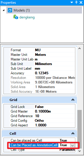
单元模型设置
示例:
public void AddAnnotationScaleTest1()
{
//因为目前暂未提供有直接使用代码创建参数化单元的方法,因此需要首先导入一个参数化单元以执行接下来的操作
//在导入单元需要注意,单元所在的模型设置中:Can be placed as AnnotationCell为True
//代码执行后调整模型中的Annotation Scale时可以发现:该参数化实例在模型中会进行实时变化
Session.Instance.Keyin("attach library");//通过模拟输入keyin的方式导入参数化单元
string paraCellName = string.Empty;//用于储存单元名称的字符串
CellLibraryOptions opts = CellLibraryOptions.Include3d | CellLibraryOptions.IncludeAllLibraries | CellLibraryOptions.IncludeParametric;//设置单元库筛选条件,这里囊括3D单元与参数化单元
CellLibraryCollection libs = new CellLibraryCollection(opts);//使用筛选条件获得单元集
DgnModel cellModel = null;//用于储存存储单元的模型
foreach (CellLibraryInfo lib in libs)//遍历单元集
{
if (lib.Type== CellLibraryType.Parametric&&lib.IsAnnotation==true)//判断单元是否是参数化同时是可注释的
{
cellModel = lib.File.LoadRootModelById(out StatusInt status, lib.File.FindModelIdByName(lib.Name), true, false, true);//获得符合条件的单元模型
paraCellName = cellModel.ModelName;//记录单元名称
break;//跳出循环
}
}
if(cellModel!=null)//判断是否获得符合条件的单元
{
DgnFile dgnFile = Session.Instance.GetActiveDgnFile();//获得当前激活的文件
DgnModel dgnModel = Session.Instance.GetActiveDgnModel();//获得当前激活的模型空间
DgnModelRef dgnModelRef = Session.Instance.GetActiveDgnModelRef();//获得当前激活的模型
DgnComponentDefinitionHandler hdlr = DgnComponentDefinitionHandler.GetForModel(cellModel);//从模型中获取定义句柄
hdlr.DefinitionModelHandler.CreateCellDefinition(dgnFile);//使用句柄创建单元定义
ParametricCellDefinitionElement pcDef = ParametricCellDefinitionElement.FindByName(paraCellName, dgnFile);//根据名称在文件中获取参数化定义元素
ParametricCellElement pc = ParametricCellElement.Create(pcDef, null, dgnModel);//使用参数化定义元素创建参数化元素
StatusInt status = pc.AddAnnotationScale(dgnModelRef);//对参数化元素添加注释比例
DTransform3d trans = DTransform3d.Identity;//声明变换矩阵
TransformInfo transInfo = new TransformInfo(trans);//声明变换信息
pc.ApplyTransform(transInfo);//对参数化单元应用变换信息
pc.AddToModel();//将参数化单元写入模型
}
else
{
MessageBox.Show("Can not find parametric cell with Can be placed as AnnotationCell = True!");//对话框提示无法找到具用注释比例的参数化单元
}
}
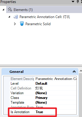
导入模型的单元
| public AnnotationHandler AsAnnotationHandler( ) |
|---|
功能说明:
获得参数化单元上的注释比例句柄,用以查询,编辑注释比例的相关信息
输入:
无
输出:
AnnotationHandler:参数化单元上的注释比例句柄
示例:
public void AsAnnotationHandlerTest1()
{
//因为目前暂未提供有直接使用代码创建参数化单元的方法,因此需要首先导入一个参数化单元以执行接下来的操作
//在导入单元需要注意,单元所在的模型设置中:Can be placed as AnnotationCell为True
//代码执行后调整模型中的Annotation Scale时可以发现:该参数化实例在模型中会进行实时变化
Session.Instance.Keyin("attach library");//通过模拟输入keyin的方式导入参数化单元
string paraCellName = string.Empty;//用于储存单元名称的字符串
CellLibraryOptions opts = CellLibraryOptions.Include3d | CellLibraryOptions.IncludeAllLibraries | CellLibraryOptions.IncludeParametric;//设置单元库筛选条件,这里囊括3D单元与参数化单元
CellLibraryCollection libs = new CellLibraryCollection(opts);//使用筛选条件获得单元集
DgnModel cellModel = null;//用于储存存储单元的模型
foreach (CellLibraryInfo lib in libs)//遍历单元集
{
if (lib.Type == CellLibraryType.Parametric)//判断单元是否是参数化
{
cellModel = lib.File.LoadRootModelById(out StatusInt status, lib.File.FindModelIdByName(lib.Name), true, false, true);//获得符合条件的单元模型
paraCellName = cellModel.ModelName;//记录单元名称
break;//跳出循环
}
}
if (cellModel != null)//判断是否获得符合条件的单元
{
DgnFile dgnFile = Session.Instance.GetActiveDgnFile();//获得当前激活的文件
DgnModel dgnModel = Session.Instance.GetActiveDgnModel();//获得当前激活的模型空间
DgnModelRef dgnModelRef = Session.Instance.GetActiveDgnModelRef();//获得当前激活的模型
DgnComponentDefinitionHandler hdlr = DgnComponentDefinitionHandler.GetForModel(cellModel);//从模型中获取定义句柄
hdlr.DefinitionModelHandler.CreateCellDefinition(dgnFile);//使用句柄创建单元定义
ParametricCellDefinitionElement pcDef = ParametricCellDefinitionElement.FindByName(paraCellName, dgnFile);//根据名称在文件中获取参数化定义元素
ParametricCellElement pc = ParametricCellElement.Create(pcDef, null, dgnModel);//使用参数化定义元素创建参数化元素
StatusInt status = pc.AddAnnotationScale(dgnModelRef);//对参数化元素添加注释比例
DTransform3d trans = DTransform3d.Identity;//声明变换矩阵
TransformInfo transInfo = new TransformInfo(trans);//声明变换信息
pc.ApplyTransform(transInfo);//对参数化单元应用变换信息
pc.AddToModel();//将参数化单元写入模型
AnnotationHandler handler= pc.AsAnnotationHandler();//获得参数化单元上的注释比例句柄,用以查询,编辑注释比例的相关信息
bool result= handler.HasAnnotationScale(out double scale);//获得注释比例句柄中是否存在注释比例,若有输出比例大小
if(result==true)//若存在注释比例
{
MessageBox.Show(paraCellName+" has annotation scale that is "+result+" ,the scale is "+scale);//对话框提示参数化单元拥有注释比例并输出比例大小
}
else
{
MessageBox.Show(paraCellName + " has annotation scale that is " + result);//对话框提示参数化单元不拥有注释比例
}
}
else
{
MessageBox.Show("Can not find parametric cell");//对话框提示无法找到参数化单元
}
}
| public void ClearPresentation( ) |
|---|
功能说明:
清除展示图形
输入:
无
输出:
无
示例:
暂无
| public static ParametricCellElement Create( ParametricCellDefinitionElement cellDef, string parameterSetName, DgnModel placementModel ) |
|---|
功能说明:
创建参数化单元的实例
输入:
ParametricCellDefinitionElement cellDef:参数化单元定义
string parameterSetName:参数化单元名称
DgnModel placementModel:放置参数化单元的模型空间
输出:
ParametricCellElement:参数化单元
示例:
public void CreateTest1()
{
//因为目前暂未提供有直接使用代码创建参数化单元的方法,因此需要首先导入一个参数化单元以执行接下来的操作
//在导入单元需要注意,单元所在的模型设置中:Can be placed as AnnotationCell为True
//代码执行后调整模型中的Annotation Scale时可以发现:该参数化实例在模型中会进行实时变化
Session.Instance.Keyin("attach library");//通过模拟输入keyin的方式导入参数化单元
string paraCellName = string.Empty;//用于储存单元名称的字符串
CellLibraryOptions opts = CellLibraryOptions.Include3d | CellLibraryOptions.IncludeAllLibraries | CellLibraryOptions.IncludeParametric;//设置单元库筛选条件,这里囊括3D单元与参数化单元
CellLibraryCollection libs = new CellLibraryCollection(opts);//使用筛选条件获得单元集
DgnModel cellModel = null;//用于储存存储单元的模型
foreach (CellLibraryInfo lib in libs)//遍历单元集
{
if (lib.Type == CellLibraryType.Parametric)//判断单元是否是参数化
{
cellModel = lib.File.LoadRootModelById(out StatusInt status, lib.File.FindModelIdByName(lib.Name), true, false, true);//获得符合条件的单元模型
paraCellName = cellModel.ModelName;//记录单元名称
break;//跳出循环
}
}
if (cellModel != null)//判断是否获得符合条件的单元
{
DgnFile dgnFile = Session.Instance.GetActiveDgnFile();//获得当前激活的文件
DgnModel dgnModel = Session.Instance.GetActiveDgnModel();//获得当前激活的模型空间
DgnModelRef dgnModelRef = Session.Instance.GetActiveDgnModelRef();//获得当前激活的模型
DgnComponentDefinitionHandler hdlr = DgnComponentDefinitionHandler.GetForModel(cellModel);//从模型中获取定义句柄
hdlr.DefinitionModelHandler.CreateCellDefinition(dgnFile);//使用句柄创建单元定义
ParametricCellDefinitionElement pcDef = ParametricCellDefinitionElement.FindByName(paraCellName, dgnFile);//根据名称在文件中获取参数化定义元素
ParametricCellElement pc = ParametricCellElement.Create(pcDef, null, dgnModel);//使用参数化定义元素创建参数化元素
StatusInt status = pc.AddAnnotationScale(dgnModelRef);//对参数化元素添加注释比例
DTransform3d trans = DTransform3d.Identity;//声明变换矩阵
TransformInfo transInfo = new TransformInfo(trans);//声明变换信息
pc.ApplyTransform(transInfo);//对参数化单元应用变换信息
pc.AddToModel();//将参数化单元写入模型
}
else
{
MessageBox.Show("Can not find parametric cell");//对话框提示无法找到参数化单元
}
}
| public static ParametricCellElement Create( ParametricCellDefinitionElement cellDef, string parameterSetName, DgnModel placementModel, uint index ) |
|---|
功能说明:
创建参数化单元的实例
输入:
ParametricCellDefinitionElement cellDef:参数化单元定义
string parameterSetName:参数化单元名称
DgnModel placementModel:放置参数化单元的模型空间
uint index:单元索引
输出:
ParametricCellElement:参数化单元
示例:
暂无
| public bool HasAnnotationScale( out double annotationScale ) |
|---|
功能说明:
查询参数化单元是否拥有注释比例
输入:
out double annotationScale:(输出)参数化单元拥有的注释比例值
输出:
bool:参数化单元是否拥有注释比例
示例:
public void HasAnnotationScaleTest1()
{
//因为目前暂未提供有直接使用代码创建参数化单元的方法,因此需要首先导入一个参数化单元以执行接下来的操作
//在导入单元需要注意,单元所在的模型设置中:Can be placed as AnnotationCell为True
//代码执行后调整模型中的Annotation Scale时可以发现:该参数化实例在模型中会进行实时变化
Session.Instance.Keyin("attach library");//通过模拟输入keyin的方式导入参数化单元
string paraCellName = string.Empty;//用于储存单元名称的字符串
CellLibraryOptions opts = CellLibraryOptions.Include3d | CellLibraryOptions.IncludeAllLibraries | CellLibraryOptions.IncludeParametric;//设置单元库筛选条件,这里囊括3D单元与参数化单元
CellLibraryCollection libs = new CellLibraryCollection(opts);//使用筛选条件获得单元集
DgnModel cellModel = null;//用于储存存储单元的模型
foreach (CellLibraryInfo lib in libs)//遍历单元集
{
if (lib.Type == CellLibraryType.Parametric)//判断单元是否是参数化
{
cellModel = lib.File.LoadRootModelById(out StatusInt status, lib.File.FindModelIdByName(lib.Name), true, false, true);//获得符合条件的单元模型
paraCellName = cellModel.ModelName;//记录单元名称
break;//跳出循环
}
}
if (cellModel != null)//判断是否获得符合条件的单元
{
DgnFile dgnFile = Session.Instance.GetActiveDgnFile();//获得当前激活的文件
DgnModel dgnModel = Session.Instance.GetActiveDgnModel();//获得当前激活的模型空间
DgnModelRef dgnModelRef = Session.Instance.GetActiveDgnModelRef();//获得当前激活的模型
DgnComponentDefinitionHandler hdlr = DgnComponentDefinitionHandler.GetForModel(cellModel);//从模型中获取定义句柄
hdlr.DefinitionModelHandler.CreateCellDefinition(dgnFile);//使用句柄创建单元定义
ParametricCellDefinitionElement pcDef = ParametricCellDefinitionElement.FindByName(paraCellName, dgnFile);//根据名称在文件中获取参数化定义元素
ParametricCellElement pc = ParametricCellElement.Create(pcDef, null, dgnModel);//使用参数化定义元素创建参数化元素
StatusInt status = pc.AddAnnotationScale(dgnModelRef);//对参数化元素添加注释比例
DTransform3d trans = DTransform3d.Identity;//声明变换矩阵
TransformInfo transInfo = new TransformInfo(trans);//声明变换信息
pc.ApplyTransform(transInfo);//对参数化单元应用变换信息
pc.AddToModel();//将参数化单元写入模型
AnnotationHandler handler = pc.AsAnnotationHandler();//获得参数化单元上的注释比例句柄,用以查询,编辑注释比例的相关信息
bool result = handler.HasAnnotationScale(out double scale);//获得注释比例句柄中是否存在注释比例,若有输出比例大小
if (result == true)//若存在注释比例
{
MessageBox.Show(paraCellName + " has annotation scale that is " + result + " ,the scale is " + scale);//对话框提示参数化单元拥有注释比例并输出比例大小
}
else
{
MessageBox.Show(paraCellName + " has annotation scale that is " + result);//对话框提示参数化单元不拥有注释比例
}
}
else
{
MessageBox.Show("Can not find parametric cell!");//对话框提示无法找到参数化单元
}
}
| public bool IsPlacementPointsDisplayed( ) |
|---|
功能说明:
判断参数化单元的放置点是否可见
输入:
无
输出:
bool:参数化单元的放置点是否可见
示例:
暂无
| public bool IsPlacementPointsHidden() |
|---|
功能说明:
判断参数化单元的放置点是否隐藏
输入:
无
输出:
bool:参数化单元的放置点是否隐藏
示例:
暂无
| public StatusInt RemoveAnnotationScale( ) |
|---|
功能说明:
移除参数化单元上的注释比例
输入:
无
输出:
StatusInt:若参数化单元上的注释比例被移除则返回成功
示例:
public void RemoveAnnotationScaleTest1()
{
//因为目前暂未提供有直接使用代码创建参数化单元的方法,因此需要首先导入一个参数化单元以执行接下来的操作
//在导入单元需要注意,单元所在的模型设置中:Can be placed as AnnotationCell为True
//代码执行后调整模型中的Annotation Scale时可以发现:该参数化实例在模型中会进行实时变化
Session.Instance.Keyin("attach library");//通过模拟输入keyin的方式导入参数化单元
string paraCellName = string.Empty;//用于储存单元名称的字符串
CellLibraryOptions opts = CellLibraryOptions.Include3d | CellLibraryOptions.IncludeAllLibraries | CellLibraryOptions.IncludeParametric;//设置单元库筛选条件,这里囊括3D单元与参数化单元
CellLibraryCollection libs = new CellLibraryCollection(opts);//使用筛选条件获得单元集
DgnModel cellModel = null;//用于储存存储单元的模型
foreach (CellLibraryInfo lib in libs)//遍历单元集
{
if (lib.Type == CellLibraryType.Parametric && lib.IsAnnotation == true)//判断单元是否是参数化同时是可注释的
{
cellModel = lib.File.LoadRootModelById(out StatusInt status, lib.File.FindModelIdByName(lib.Name), true, false, true);//获得符合条件的单元模型
paraCellName = cellModel.ModelName;//记录单元名称
break;//跳出循环
}
}
if (cellModel != null)//判断是否获得符合条件的单元
{
DgnFile dgnFile = Session.Instance.GetActiveDgnFile();//获得当前激活的文件
DgnModel dgnModel = Session.Instance.GetActiveDgnModel();//获得当前激活的模型空间
DgnModelRef dgnModelRef = Session.Instance.GetActiveDgnModelRef();//获得当前激活的模型
DgnComponentDefinitionHandler hdlr = DgnComponentDefinitionHandler.GetForModel(cellModel);//从模型中获取定义句柄
hdlr.DefinitionModelHandler.CreateCellDefinition(dgnFile);//使用句柄创建单元定义
ParametricCellDefinitionElement pcDef = ParametricCellDefinitionElement.FindByName(paraCellName, dgnFile);//根据名称在文件中获取参数化定义元素
ParametricCellElement pc = ParametricCellElement.Create(pcDef, null, dgnModel);//使用参数化定义元素创建参数化元素
StatusInt status = pc.AddAnnotationScale(dgnModelRef);//对参数化元素添加注释比例
DTransform3d trans = DTransform3d.Identity;//声明变换矩阵
TransformInfo transInfo = new TransformInfo(trans);//声明变换信息
pc.ApplyTransform(transInfo);//对参数化单元应用变换信息
pc.AddToModel();//将参数化单元写入模型
ParametricCellElement pc2 = ParametricCellElement.Create(pcDef, null, dgnModel);//使用参数化定义元素创建参数化元素
pc2.AddAnnotationScale(dgnModelRef);//对参数化元素添加注释比例
pc2.ApplyTransform(transInfo);//对参数化单元应用变换信息
pc2.RemoveAnnotationScale();//移除参数化单元上的注释比例
pc2.AddToModel();//将参数化单元写入模型
}
else
{
MessageBox.Show("Can not find parametric cell with Can be placed as AnnotationCell = True!");//对话框提示无法找到具用注释比例的参数化单元
}
}
| public void SetDisplayStateOfPlacementPoint( bool invisible ) |
|---|
功能说明:
设置参数化单元放置点的显示状态
输入:
bool invisible:参数化单元放置点是否可见
输出:
void:无
示例:
暂无
| public void SetStickyPoint( uint index ) |
|---|
功能说明:
设置参数化单元的粘滞点
输入:
uint index:粘滞点索引
输出:
无
示例:
暂无
| public void ValidatePresentation( ) |
|---|
功能说明:
生成或更新参数化单元的状态。此方法将引起 _GeneratePresentation执行更新,当元素中_AutoGeneratePresentation为真时则无需调用此方法
输入:
无
输出:
无
示例:
暂无
属性:
| public ParametricCellDefinitionElement CellDefinition { get; } |
|---|
功能说明:
获得参数化单元实例的参数化单元定义元素
属性:
只读
输出:
ParametricCellDefinitionElement:参数化单元定义元素
示例:
public void CellDefinitionTest1()
{
//因为目前暂未提供有直接使用代码创建参数化单元的方法,因此需要首先导入一个参数化单元以执行接下来的操作
//在导入单元需要注意,单元所在的模型设置中:Can be placed as AnnotationCell为True
//代码执行后调整模型中的Annotation Scale时可以发现:该参数化实例在模型中会进行实时变化
Session.Instance.Keyin("attach library");//通过模拟输入keyin的方式导入参数化单元
string paraCellName = string.Empty;//用于储存单元名称的字符串
CellLibraryOptions opts = CellLibraryOptions.Include3d | CellLibraryOptions.IncludeAllLibraries | CellLibraryOptions.IncludeParametric;//设置单元库筛选条件,这里囊括3D单元与参数化单元
CellLibraryCollection libs = new CellLibraryCollection(opts);//使用筛选条件获得单元集
DgnModel cellModel = null;//用于储存存储单元的模型
foreach (CellLibraryInfo lib in libs)//遍历单元集
{
if (lib.Type == CellLibraryType.Parametric)//判断单元是否是参数化
{
cellModel = lib.File.LoadRootModelById(out StatusInt status, lib.File.FindModelIdByName(lib.Name), true, false, true);//获得符合条件的单元模型
paraCellName = cellModel.ModelName;//记录单元名称
break;//跳出循环
}
}
if (cellModel != null)//判断是否获得符合条件的单元
{
DgnFile dgnFile = Session.Instance.GetActiveDgnFile();//获得当前激活的文件
DgnModel dgnModel = Session.Instance.GetActiveDgnModel();//获得当前激活的模型空间
DgnModelRef dgnModelRef = Session.Instance.GetActiveDgnModelRef();//获得当前激活的模型
DgnComponentDefinitionHandler hdlr = DgnComponentDefinitionHandler.GetForModel(cellModel);//从模型中获取定义句柄
hdlr.DefinitionModelHandler.CreateCellDefinition(dgnFile);//使用句柄创建单元定义
ParametricCellDefinitionElement pcDef = ParametricCellDefinitionElement.FindByName(paraCellName, dgnFile);//根据名称在文件中获取参数化定义元素
ParametricCellElement pc = ParametricCellElement.Create(pcDef, null, dgnModel);//使用参数化定义元素创建参数化元素
StatusInt status = pc.AddAnnotationScale(dgnModelRef);//对参数化元素添加注释比例
DTransform3d trans = DTransform3d.Identity;//声明变换矩阵
TransformInfo transInfo = new TransformInfo(trans);//声明变换信息
pc.ApplyTransform(transInfo);//对参数化单元应用变换信息
pc.AddToModel();//将参数化单元写入模型
ParametricCellDefinitionElement defElem= pc.CellDefinition;//获得参数化单元实例的参数化单元定义元素
MessageBox.Show("The name of ParametricCellDefinitionElement is "+defElem.CellName);//对话框输出参数化单元实例的参数化单元定义元素名称
}
else
{
MessageBox.Show("Can not find parametric cell");//对话框提示无法找到参数化单元
}
}
| public bool IsAnnotation { get; } |
|---|
功能说明:
判断参数化单元元素是否拥有注释定义
属性:
只读
输出:
bool:参数化单元元素是否拥有注释定义的结果
示例:
public void IsAnnotationTest1()
{
//因为目前暂未提供有直接使用代码创建参数化单元的方法,因此需要首先导入一个参数化单元以执行接下来的操作
//在导入单元需要注意,单元所在的模型设置中:Can be placed as AnnotationCell为True
//代码执行后调整模型中的Annotation Scale时可以发现:该参数化实例在模型中会进行实时变化
Session.Instance.Keyin("attach library");//通过模拟输入keyin的方式导入参数化单元
string paraCellName = string.Empty;//用于储存单元名称的字符串
CellLibraryOptions opts = CellLibraryOptions.Include3d | CellLibraryOptions.IncludeAllLibraries | CellLibraryOptions.IncludeParametric;//设置单元库筛选条件,这里囊括3D单元与参数化单元
CellLibraryCollection libs = new CellLibraryCollection(opts);//使用筛选条件获得单元集
DgnModel cellModel = null;//用于储存存储单元的模型
foreach (CellLibraryInfo lib in libs)//遍历单元集
{
if (lib.Type == CellLibraryType.Parametric)//判断单元是否是参数化
{
cellModel = lib.File.LoadRootModelById(out StatusInt status, lib.File.FindModelIdByName(lib.Name), true, false, true);//获得符合条件的单元模型
paraCellName = cellModel.ModelName;//记录单元名称
break;//跳出循环
}
}
if (cellModel != null)//判断是否获得符合条件的单元
{
DgnFile dgnFile = Session.Instance.GetActiveDgnFile();//获得当前激活的文件
DgnModel dgnModel = Session.Instance.GetActiveDgnModel();//获得当前激活的模型空间
DgnModelRef dgnModelRef = Session.Instance.GetActiveDgnModelRef();//获得当前激活的模型
DgnComponentDefinitionHandler hdlr = DgnComponentDefinitionHandler.GetForModel(cellModel);//从模型中获取定义句柄
hdlr.DefinitionModelHandler.CreateCellDefinition(dgnFile);//使用句柄创建单元定义
ParametricCellDefinitionElement pcDef = ParametricCellDefinitionElement.FindByName(paraCellName, dgnFile);//根据名称在文件中获取参数化定义元素
ParametricCellElement pc = ParametricCellElement.Create(pcDef, null, dgnModel);//使用参数化定义元素创建参数化元素
StatusInt status = pc.AddAnnotationScale(dgnModelRef);//对参数化元素添加注释比例
DTransform3d trans = DTransform3d.Identity;//声明变换矩阵
TransformInfo transInfo = new TransformInfo(trans);//声明变换信息
pc.ApplyTransform(transInfo);//对参数化单元应用变换信息
pc.AddToModel();//将参数化单元写入模型
bool result = pc.IsAnnotation;
MessageBox.Show(paraCellName + " has annotation scale that is " + result);//对话框提示参数化单元是否拥有注释比例的结果
}
else
{
MessageBox.Show("Can not find parametric cell!");//对话框提示无法找到参数化单元
}
}
| public DPoint3d Origin { get; set; } |
|---|
功能说明:
修改或获取参数化单元元素的坐标点
属性:
可读可写
输出:
DPoint3d:参数化单元元素的坐标点
示例:
public void OriginTest1()
{
//因为目前暂未提供有直接使用代码创建参数化单元的方法,因此需要首先导入一个参数化单元以执行接下来的操作
//在导入单元需要注意,单元所在的模型设置中:Can be placed as AnnotationCell为True
//代码执行后调整模型中的Annotation Scale时可以发现:该参数化实例在模型中会进行实时变化
Session.Instance.Keyin("attach library");//通过模拟输入keyin的方式导入参数化单元
string paraCellName = string.Empty;//用于储存单元名称的字符串
CellLibraryOptions opts = CellLibraryOptions.Include3d | CellLibraryOptions.IncludeAllLibraries | CellLibraryOptions.IncludeParametric;//设置单元库筛选条件,这里囊括3D单元与参数化单元
CellLibraryCollection libs = new CellLibraryCollection(opts);//使用筛选条件获得单元集
DgnModel cellModel = null;//用于储存存储单元的模型
foreach (CellLibraryInfo lib in libs)//遍历单元集
{
if (lib.Type == CellLibraryType.Parametric)//判断单元是否是参数化
{
cellModel = lib.File.LoadRootModelById(out StatusInt status, lib.File.FindModelIdByName(lib.Name), true, false, true);//获得符合条件的单元模型
paraCellName = cellModel.ModelName;//记录单元名称
break;//跳出循环
}
}
if (cellModel != null)//判断是否获得符合条件的单元
{
DgnFile dgnFile = Session.Instance.GetActiveDgnFile();//获得当前激活的文件
DgnModel dgnModel = Session.Instance.GetActiveDgnModel();//获得当前激活的模型空间
DgnModelRef dgnModelRef = Session.Instance.GetActiveDgnModelRef();//获得当前激活的模型
DgnComponentDefinitionHandler hdlr = DgnComponentDefinitionHandler.GetForModel(cellModel);//从模型中获取定义句柄
hdlr.DefinitionModelHandler.CreateCellDefinition(dgnFile);//使用句柄创建单元定义
ParametricCellDefinitionElement pcDef = ParametricCellDefinitionElement.FindByName(paraCellName, dgnFile);//根据名称在文件中获取参数化定义元素
ParametricCellElement pc = ParametricCellElement.Create(pcDef, null, dgnModel);//使用参数化定义元素创建参数化元素
StatusInt status = pc.AddAnnotationScale(dgnModelRef);//对参数化元素添加注释比例
DTransform3d trans = DTransform3d.Identity;//声明变换矩阵
TransformInfo transInfo = new TransformInfo(trans);//声明变换信息
pc.ApplyTransform(transInfo);//对参数化单元应用变换信息
pc.Origin = new DPoint3d(100000,0,0);//修改参数化单元元素的坐标点
pc.AddToModel();//将参数化单元写入模型
MessageBox.Show(paraCellName + "'s origin is " + pc.Origin);//对话框提示参数化单元的坐标点
}
else
{
MessageBox.Show("Can not find parametric cell!");//对话框提示无法找到参数化单元
}
}
| public IECInstance Parameters { get; } |
|---|
功能说明:
获得参数化单元参数的EC实例
属性:
只读
输出:
IECInstance:参数化单元参数的EC实例
示例:
public void ParametersTest1()
{
//因为目前暂未提供有直接使用代码创建参数化单元的方法,因此需要首先导入一个参数化单元以执行接下来的操作
//在导入单元需要注意,单元所在的模型设置中:Can be placed as AnnotationCell为True
//代码执行后调整模型中的Annotation Scale时可以发现:该参数化实例在模型中会进行实时变化
Session.Instance.Keyin("attach library");//通过模拟输入keyin的方式导入参数化单元
string paraCellName = string.Empty;//用于储存单元名称的字符串
CellLibraryOptions opts = CellLibraryOptions.Include3d | CellLibraryOptions.IncludeAllLibraries | CellLibraryOptions.IncludeParametric;//设置单元库筛选条件,这里囊括3D单元与参数化单元
CellLibraryCollection libs = new CellLibraryCollection(opts);//使用筛选条件获得单元集
DgnModel cellModel = null;//用于储存存储单元的模型
foreach (CellLibraryInfo lib in libs)//遍历单元集
{
if (lib.Type == CellLibraryType.Parametric)//判断单元是否是参数化
{
cellModel = lib.File.LoadRootModelById(out StatusInt status, lib.File.FindModelIdByName(lib.Name), true, false, true);//获得符合条件的单元模型
paraCellName = cellModel.ModelName;//记录单元名称
break;//跳出循环
}
}
if (cellModel != null)//判断是否获得符合条件的单元
{
DgnFile dgnFile = Session.Instance.GetActiveDgnFile();//获得当前激活的文件
DgnModel dgnModel = Session.Instance.GetActiveDgnModel();//获得当前激活的模型空间
DgnModelRef dgnModelRef = Session.Instance.GetActiveDgnModelRef();//获得当前激活的模型
DgnComponentDefinitionHandler hdlr = DgnComponentDefinitionHandler.GetForModel(cellModel);//从模型中获取定义句柄
hdlr.DefinitionModelHandler.CreateCellDefinition(dgnFile);//使用句柄创建单元定义
ParametricCellDefinitionElement pcDef = ParametricCellDefinitionElement.FindByName(paraCellName, dgnFile);//根据名称在文件中获取参数化定义元素
ParametricCellElement pc = ParametricCellElement.Create(pcDef, null, dgnModel);//使用参数化定义元素创建参数化元素
StatusInt status = pc.AddAnnotationScale(dgnModelRef);//对参数化元素添加注释比例
DTransform3d trans = DTransform3d.Identity;//声明变换矩阵
TransformInfo transInfo = new TransformInfo(trans);//声明变换信息
pc.ApplyTransform(transInfo);//对参数化单元应用变换信息
pc.AddToModel();//将参数化单元写入模型
IECInstance instance = pc.Parameters;//获得参数化单元参数的EC实例
IECArrayValue arr = instance.GetPropertyValue("ParameterValuesContainer") as IECArrayValue;//获得EC参数化值列表
IECStructValue structVal = arr[1] as IECStructValue;//获得EC结构值
structVal.TryGetStringValue(out string value);//获取其中储存的字符值
MessageBox.Show("Properties value string is:\n"+value);//输出获得的储存字符值
}
else
{
MessageBox.Show("Can not find parametric cell!");//对话框提示无法找到参数化单元
}
}
| public string ParameterSetName { get; set; } |
|---|
功能说明:
修改或获得参数化单元的参数定义名
属性:
可读可写
输出:
string:参数化单元的参数定义名
示例:
public void ParameterSetNameTest1()
{
//因为目前暂未提供有直接使用代码创建参数化单元的方法,因此需要首先导入一个参数化单元以执行接下来的操作
//在导入单元需要注意,单元所在的模型设置中:Can be placed as AnnotationCell为True
//代码执行后调整模型中的Annotation Scale时可以发现:该参数化实例在模型中会进行实时变化
Session.Instance.Keyin("attach library");//通过模拟输入keyin的方式导入参数化单元
string paraCellName = string.Empty;//用于储存单元名称的字符串
CellLibraryOptions opts = CellLibraryOptions.Include3d | CellLibraryOptions.IncludeAllLibraries | CellLibraryOptions.IncludeParametric;//设置单元库筛选条件,这里囊括3D单元与参数化单元
CellLibraryCollection libs = new CellLibraryCollection(opts);//使用筛选条件获得单元集
DgnModel cellModel = null;//用于储存存储单元的模型
foreach (CellLibraryInfo lib in libs)//遍历单元集
{
if (lib.Type == CellLibraryType.Parametric)//判断单元是否是参数化
{
cellModel = lib.File.LoadRootModelById(out StatusInt status, lib.File.FindModelIdByName(lib.Name), true, false, true);//获得符合条件的单元模型
paraCellName = cellModel.ModelName;//记录单元名称
break;//跳出循环
}
}
if (cellModel != null)//判断是否获得符合条件的单元
{
DgnFile dgnFile = Session.Instance.GetActiveDgnFile();//获得当前激活的文件
DgnModel dgnModel = Session.Instance.GetActiveDgnModel();//获得当前激活的模型空间
DgnModelRef dgnModelRef = Session.Instance.GetActiveDgnModelRef();//获得当前激活的模型
DgnComponentDefinitionHandler hdlr = DgnComponentDefinitionHandler.GetForModel(cellModel);//从模型中获取定义句柄
hdlr.DefinitionModelHandler.CreateCellDefinition(dgnFile);//使用句柄创建单元定义
ParametricCellDefinitionElement pcDef = ParametricCellDefinitionElement.FindByName(paraCellName, dgnFile);//根据名称在文件中获取参数化定义元素
ParametricCellElement pc = ParametricCellElement.Create(pcDef, null, dgnModel);//使用参数化定义元素创建参数化元素
DTransform3d trans = DTransform3d.Identity;//声明变换矩阵
TransformInfo transInfo = new TransformInfo(trans);//声明变换信息
pc.ApplyTransform(transInfo);//对参数化单元应用变换信息
pc.AddToModel();//将参数化单元写入模型
MessageBox.Show("The parameter set name of parameter cell is "+ pc.ParameterSetName);//对话框提示参数化单元的参数定义名
}
else
{
MessageBox.Show("Can not find parametric cell!");//对话框提示无法找到参数化单元
}
}
| public DMatrix3d Rotation { get; set; } |
|---|
功能说明:
查询或修改参数化单元的变换矩阵
属性:
可读可写
输出:
DMatrix3d:参数化单元的变换矩阵
示例:
public void RotationTest1()
{
//因为目前暂未提供有直接使用代码创建参数化单元的方法,因此需要首先导入一个参数化单元以执行接下来的操作
//在导入单元需要注意,单元所在的模型设置中:Can be placed as AnnotationCell为True
//代码执行后调整模型中的Annotation Scale时可以发现:该参数化实例在模型中会进行实时变化
Session.Instance.Keyin("attach library");//通过模拟输入keyin的方式导入参数化单元
string paraCellName = string.Empty;//用于储存单元名称的字符串
CellLibraryOptions opts = CellLibraryOptions.Include3d | CellLibraryOptions.IncludeAllLibraries | CellLibraryOptions.IncludeParametric;//设置单元库筛选条件,这里囊括3D单元与参数化单元
CellLibraryCollection libs = new CellLibraryCollection(opts);//使用筛选条件获得单元集
DgnModel cellModel = null;//用于储存存储单元的模型
foreach (CellLibraryInfo lib in libs)//遍历单元集
{
if (lib.Type == CellLibraryType.Parametric)//判断单元是否是参数化
{
cellModel = lib.File.LoadRootModelById(out StatusInt status, lib.File.FindModelIdByName(lib.Name), true, false, true);//获得符合条件的单元模型
paraCellName = cellModel.ModelName;//记录单元名称
break;//跳出循环
}
}
if (cellModel != null)//判断是否获得符合条件的单元
{
DgnFile dgnFile = Session.Instance.GetActiveDgnFile();//获得当前激活的文件
DgnModel dgnModel = Session.Instance.GetActiveDgnModel();//获得当前激活的模型空间
DgnModelRef dgnModelRef = Session.Instance.GetActiveDgnModelRef();//获得当前激活的模型
DgnComponentDefinitionHandler hdlr = DgnComponentDefinitionHandler.GetForModel(cellModel);//从模型中获取定义句柄
hdlr.DefinitionModelHandler.CreateCellDefinition(dgnFile);//使用句柄创建单元定义
ParametricCellDefinitionElement pcDef = ParametricCellDefinitionElement.FindByName(paraCellName, dgnFile);//根据名称在文件中获取参数化定义元素
ParametricCellElement pc = ParametricCellElement.Create(pcDef, null, dgnModel);//使用参数化定义元素创建参数化元素
pc.Rotation = new DMatrix3d(0, 1, 0, 0, 0, 1, 1, 0, 0);//修改参数化单元的变换矩阵
DTransform3d trans = DTransform3d.Identity;//声明变换矩阵
TransformInfo transInfo = new TransformInfo(trans);//声明变换信息
pc.ApplyTransform(transInfo);//对参数化单元应用变换信息
pc.AddToModel();//将参数化单元写入模型
}
else
{
MessageBox.Show("Can not find parametric cell!");//对话框提示无法找到参数化单元
}
}
1.2.23 PointCloudElement
说明:
点云元素
方法:
| public PointCloudElement( DgnModel model, PointCloudProperties pointCloudProperties, DRange3d range ) |
|---|
功能说明:
创建一个点云元素的实例
输入:
DgnModel model:写入点云元素的模型空间
PointCloudProperties pointCloudProperties:点云属性。使用PointCloudProperties::Create可创建属性
DRange3d range:元素创建的范围。因为该方法不会打开点云文件中的范围信息因此对于创建点云元素该参数很重要
输出:
PointCloudElement:点云元素的实例
示例:
public void PointCloudElementTest1()
{
//您需要提前准备一个点云文件(*.pod),用以建立点云元素
OpenFileDialog fileDialog = new OpenFileDialog();//调用文件对话框获取文件路径
fileDialog.Title = "Please select a point cloud file";//设置对话框标题
fileDialog.Filter = "(*.pod)|*.pod";//设置文件筛选条件
DialogResult result= fileDialog.ShowDialog();//弹出对话框
if (result==DialogResult.OK)//当用户确认文件后触发
{
DgnModel dgnModel = Session.Instance.GetActiveDgnModel();//获得当前激活的模型空间
string fileName= fileDialog.FileName;//获得文件名称
string path= System.IO.Path.GetFullPath(fileDialog.FileName);//获得文件路径
DgnDocumentMoniker moniker = DgnDocumentMoniker.CreateFromFileName(fileName, path);//打开指定路径的指定文件创建文件对象
PointCloudProperties prop = new PointCloudProperties(moniker, dgnModel);//获得文件中数据生成点云属性
Bentley.DgnPlatformNET.Elements.PointCloudElement pE = new Bentley.DgnPlatformNET.Elements.PointCloudElement(dgnModel, prop, DRange3d.InfiniteRange);//声明点云元素
pE.AddToModel();//将点云元素写入模型
}
}
属性:
| public PointCloudClipProperties PointCloudClipProperties { get; set; } |
|---|
功能说明:
获得点云元素中的剪切属性
属性:
可读可写
输出:
PointCloudClipProperties:点云元素中的剪切属性
示例:
public void PointCloudClipPropertiesTest1()
{
//您需要提前准备一个点云文件(*.pod),用以建立点云元素
OpenFileDialog fileDialog = new OpenFileDialog();//调用文件对话框获取文件路径
fileDialog.Title = "Please select a point cloud file";//设置对话框标题
fileDialog.Filter = "(*.pod)|*.pod";//设置文件筛选条件
DialogResult result = fileDialog.ShowDialog();//弹出对话框
if (result == DialogResult.OK)//当用户确认文件后触发
{
DgnModel dgnModel = Session.Instance.GetActiveDgnModel();//获得当前激活的模型空间
string fileName = fileDialog.FileName;//获得文件名称
string path = System.IO.Path.GetFullPath(fileDialog.FileName);//获得文件路径
DgnDocumentMoniker moniker = DgnDocumentMoniker.CreateFromFileName(fileName, path);//打开指定路径的指定文件创建文件对象
Bentley.DgnPlatformNET.PointCloudProperties prop = new Bentley.DgnPlatformNET.PointCloudProperties(moniker, dgnModel);//获得文件中数据生成点云属性
PointCloudElement pE = new PointCloudElement(dgnModel, prop, DRange3d.InfiniteRange);//声明点云元素
pE.CalcElementRange(out DRange3d range);//计算点云元素的元素范围
OrientedBox box = new OrientedBox(new DVector3d(0.5 * range.XSize, 0, 0),
new DVector3d(0, range.YSize * 0.5, 0),
new DVector3d(0, 0, range.ZSize),
range.Low);//声明包围盒
Bentley.DgnPlatformNET.PointCloudClipProperties cloudClipProperties = new Bentley.DgnPlatformNET.PointCloudClipProperties();//声明点云剪切属性
cloudClipProperties.SetClipBoundary(prop, box);//设置剪切边界
pE.PointCloudClipProperties= cloudClipProperties;//设置点云元素的剪切属性
pE.AddToModel();//将点云元素写入模型
}
}
| public PointCloudProperties PointCloudProperties { get; set; } |
|---|
功能说明:
获得点云元素中的属性
属性:
可读可写
输出:
PointCloudProperties:点云元素中的属性
示例:
public void PointCloudPropertiesTest1()
{
//您需要提前准备一个点云文件(*.pod),用以建立点云元素
OpenFileDialog fileDialog = new OpenFileDialog();//调用文件对话框获取文件路径
fileDialog.Title = "Please select a point cloud file";//设置对话框标题
fileDialog.Filter = "(*.pod)|*.pod";//设置文件筛选条件
DialogResult result = fileDialog.ShowDialog();//弹出对话框
if (result == DialogResult.OK)//当用户确认文件后触发
{
DgnModel dgnModel = Session.Instance.GetActiveDgnModel();//获得当前激活的模型空间
string fileName = fileDialog.FileName;//获得文件名称
string path = System.IO.Path.GetFullPath(fileDialog.FileName);//获得文件路径
DgnDocumentMoniker moniker = DgnDocumentMoniker.CreateFromFileName(fileName, path);//打开指定路径的指定文件创建文件对象
Bentley.DgnPlatformNET.PointCloudProperties prop = new Bentley.DgnPlatformNET.PointCloudProperties(moniker, dgnModel);//获得文件中数据生成点云属性
PointCloudElement pE = new PointCloudElement(dgnModel, prop, DRange3d.InfiniteRange);//声明点云元素
pE.AddToModel();//将点云元素写入模型
pE.CalcElementRange(out DRange3d range);//计算点云元素的元素范围
OrientedBox box = new OrientedBox(new DVector3d(0.5 * range.XSize, 0, 0),
new DVector3d(0, range.YSize * 0.5, 0),
new DVector3d(0, 0, range.ZSize),
range.Low);//声明包围盒
Bentley.DgnPlatformNET.PointCloudClipProperties cloudClipProperties = new Bentley.DgnPlatformNET.PointCloudClipProperties();//声明点云剪切属性
cloudClipProperties.SetClipBoundary(pE.PointCloudProperties, box);//设置剪切边界
PointCloudEdit cloudEdit = PointCloudEdit.GetAsPointCloudEdit(pE);//对点云元素进行编辑
StatusInt status = cloudEdit.SetPointCloudClipProperties(cloudClipProperties);//设置点云元素的剪切属性
cloudEdit.ReplaceInModel(pE);//替换模型中的点云元素
}
}
1.2.24 PointCloudQuery
说明:
查询点云元素中的元素信息
方法:
| public static PointCloudQuery GetAsPointCloudQuery( Element element ) |
|---|
功能说明:
获取用于查询的点云元素
输入:
Element element:需要查询信息的点云元素
输出:
PointCloudQuery:用于查询的点云元素
示例:
public void GetAsPointCloudQueryTest1()
{
//您需要提前准备一个点云文件(*.pod),用以建立点云元素
OpenFileDialog fileDialog = new OpenFileDialog();//调用文件对话框获取文件路径
fileDialog.Title = "Please select a point cloud file";//设置对话框标题
fileDialog.Filter = "(*.pod)|*.pod";//设置文件筛选条件
DialogResult result = fileDialog.ShowDialog();//弹出对话框
if (result == DialogResult.OK)//当用户确认文件后触发
{
DgnModel dgnModel = Session.Instance.GetActiveDgnModel();//获得当前激活的模型空间
string fileName = fileDialog.FileName;//获得文件名称
string path = System.IO.Path.GetFullPath(fileDialog.FileName);//获得文件路径
DgnDocumentMoniker moniker = DgnDocumentMoniker.CreateFromFileName(fileName, path);//打开指定路径的指定文件创建文件对象
Bentley.DgnPlatformNET.PointCloudProperties prop = new Bentley.DgnPlatformNET.PointCloudProperties(moniker, dgnModel);//获得文件中数据生成点云属性
PointCloudElement pE = new PointCloudElement(dgnModel, prop, DRange3d.InfiniteRange);//声明点云元素
pE.AddToModel();//将点云元素写入模型
PointCloudQuery query = PointCloudQuery.GetAsPointCloudQuery(pE);//获取用于查询的点云元素
PointCloudProperties properties= query.GetPointCloudProperties();//获得点云元素的属性信息
MessageBox.Show("The global origin of the point cloud element is " + properties.GlobalOrigin);//获得点云元素的全局坐标原点
}
}
| public PointCloudClipProperties GetPointCloudClipProperties( ) |
|---|
功能说明:
获得点云元素中的剪切属性
输入:
无
输出:
PointCloudClipProperties:点云元素中的剪切属性
示例:
public void GetPointCloudClipPropertiesTest1()
{
//您需要提前准备一个点云文件(*.pod),用以建立点云元素
OpenFileDialog fileDialog = new OpenFileDialog();//调用文件对话框获取文件路径
fileDialog.Title = "Please select a point cloud file";//设置对话框标题
fileDialog.Filter = "(*.pod)|*.pod";//设置文件筛选条件
DialogResult result = fileDialog.ShowDialog();//弹出对话框
if (result == DialogResult.OK)//当用户确认文件后触发
{
DgnModel dgnModel = Session.Instance.GetActiveDgnModel();//获得当前激活的模型空间
string fileName = fileDialog.FileName;//获得文件名称
string path = System.IO.Path.GetFullPath(fileDialog.FileName);//获得文件路径
DgnDocumentMoniker moniker = DgnDocumentMoniker.CreateFromFileName(fileName, path);//打开指定路径的指定文件创建文件对象
Bentley.DgnPlatformNET.PointCloudProperties prop = new Bentley.DgnPlatformNET.PointCloudProperties(moniker, dgnModel);//获得文件中数据生成点云属性
PointCloudElement pE = new PointCloudElement(dgnModel, prop, DRange3d.InfiniteRange);//声明点云元素
pE.CalcElementRange(out DRange3d range);//计算点云元素的元素范围
OrientedBox box = new OrientedBox(new DVector3d(0.5 * range.XSize, 0, 0),
new DVector3d(0, range.YSize * 0.5, 0),
new DVector3d(0, 0, range.ZSize),
range.Low);//声明包围盒
Bentley.DgnPlatformNET.PointCloudClipProperties cloudClipProperties = new Bentley.DgnPlatformNET.PointCloudClipProperties();//声明点云剪切属性
cloudClipProperties.SetClipBoundary(prop, box);//设置剪切边界
pE.PointCloudClipProperties = cloudClipProperties;//设置点云元素的剪切属性
pE.AddToModel();//将点云元素写入模型
PointCloudQuery query = PointCloudQuery.GetAsPointCloudQuery(pE);//获取用于查询的点云元素
PointCloudClipProperties properties = query.GetPointCloudClipProperties();//获得点云元素的剪切属性信息
StatusInt status = properties.GetClipBoundary(query.GetPointCloudProperties(), out OrientedBox clipBox);//获得剪切边界的包围盒
if (status == StatusInt.Error)//当未找到包围盒时
{
MessageBox.Show("Clip bounduary not found");//对话框提示不存在剪切边界
}
else
{
MessageBox.Show("Clip bounduary found\nThe origin of the orient box is " + clipBox.Origin);//对话框提示存在剪切边界
}
}
}
| public static PointCloudClipProperties GetPointCloudClipProperties( IPointCloudQuery handler, ElementHandle eh ) |
|---|
功能说明:
获得点云元素中的剪切属性
输入:
IPointCloudQuery handler:点云查询的句柄指针
ElementHandle eh:点云元素句柄指针
输出:
PointCloudClipProperties:点云元素中的剪切属性
示例:
暂无
| public PointCloudProperties GetPointCloudProperties( ) |
|---|
功能说明:
获得点云元素中的属性
输入:
无
输出:
PointCloudProperties:点云元素中的属性
示例:
public void GetPointCloudPropertiesTest1()
{
//您需要提前准备一个点云文件(*.pod),用以建立点云元素
OpenFileDialog fileDialog = new OpenFileDialog();//调用文件对话框获取文件路径
fileDialog.Title = "Please select a point cloud file";//设置对话框标题
fileDialog.Filter = "(*.pod)|*.pod";//设置文件筛选条件
DialogResult result = fileDialog.ShowDialog();//弹出对话框
if (result == DialogResult.OK)//当用户确认文件后触发
{
DgnModel dgnModel = Session.Instance.GetActiveDgnModel();//获得当前激活的模型空间
string fileName = fileDialog.FileName;//获得文件名称
string path = System.IO.Path.GetFullPath(fileDialog.FileName);//获得文件路径
DgnDocumentMoniker moniker = DgnDocumentMoniker.CreateFromFileName(fileName, path);//打开指定路径的指定文件创建文件对象
Bentley.DgnPlatformNET.PointCloudProperties prop = new Bentley.DgnPlatformNET.PointCloudProperties(moniker, dgnModel);//获得文件中数据生成点云属性
prop.GlobalOrigin = new DPoint3d(0, 0, 10000);//设置点云元素的全局坐标
PointCloudElement pE = new PointCloudElement(dgnModel, prop, DRange3d.InfiniteRange);//声明点云元素
pE.AddToModel();//将点云元素写入模型
PointCloudQuery query = PointCloudQuery.GetAsPointCloudQuery(pE);//获取用于查询的点云元素
PointCloudProperties properties = query.GetPointCloudProperties();//获得点云元素的剪切属性信息
MessageBox.Show("The global origin of point cloud element is "+properties.GlobalOrigin);//提示框输出点云元素的全局坐标
}
}
| public static PointCloudProperties GetPointCloudProperties( IPointCloudQuery handler, ElementHandle eh ) |
|---|
功能说明:
获得点云元素中的属性
输入:
IPointCloudQuery handler:点云查询元素的句柄指针
ElementHandle eh:点云元素句柄指针
输出:
PointCloudProperties:点云元素中的属性
示例:
暂无
1.2.24.1 PointCloudEdit
说明:
用于修改点云元素属性的元素
方法:
| public static PointCloudEdit GetAsPointCloudEdit( Element managed ) |
|---|
功能说明:
转换为修改点云属性的元素
输入:
Element managed:需要修改属性的点云元素
输出:
PointCloudEdit:修改点云属性的元素
示例:
public void GetAsPointCloudEditTest1()
{
//您需要提前准备一个点云文件(*.pod),用以建立点云元素
OpenFileDialog fileDialog = new OpenFileDialog();//调用文件对话框获取文件路径
fileDialog.Title = "Please select a point cloud file";//设置对话框标题
fileDialog.Filter = "(*.pod)|*.pod";//设置文件筛选条件
DialogResult result = fileDialog.ShowDialog();//弹出对话框
if (result == DialogResult.OK)//当用户确认文件后触发
{
DgnModel dgnModel = Session.Instance.GetActiveDgnModel();//获得当前激活的模型空间
string fileName = fileDialog.FileName;//获得文件名称
string path = System.IO.Path.GetFullPath(fileDialog.FileName);//获得文件路径
DgnDocumentMoniker moniker = DgnDocumentMoniker.CreateFromFileName(fileName, path);//打开指定路径的指定文件创建文件对象
PointCloudProperties prop = new PointCloudProperties(moniker, dgnModel);//获得文件中数据生成点云属性
PointCloudElement pE = new PointCloudElement(dgnModel, prop, DRange3d.InfiniteRange);//声明点云元素
PointCloudEdit edit = PointCloudEdit.GetAsPointCloudEdit(pE);//修改点云元素的属性
PointCloudProperties properties = new PointCloudProperties(moniker,dgnModel);//获得文件中数据生成点云属性
properties.Transform = new DTransform3d(1,0,0,0,0,1,0,1,0);//设置点云元素的变换矩阵
edit.SetPointCloudProperties(properties);//修改点云元素中的属性
edit.AddToModel();//将点云元素写入模型
}
}
| public StatusInt SetPointCloudClipProperties( PointCloudClipProperties pointCloudClipProperties ) |
|---|
功能说明:
修改点云模型的剪切属性定义
输入:
PointCloudClipProperties pointCloudClipProperties:点云元素剪切属性定义
输出:
StatusInt:若失败元素无法修改定义
示例:
public void SetPointCloudClipPropertiesTest1()
{
//您需要提前准备一个点云文件(*.pod),用以建立点云元素
OpenFileDialog fileDialog = new OpenFileDialog();//调用文件对话框获取文件路径
fileDialog.Title = "Please select a point cloud file";//设置对话框标题
fileDialog.Filter = "(*.pod)|*.pod";//设置文件筛选条件
DialogResult result = fileDialog.ShowDialog();//弹出对话框
if (result == DialogResult.OK)//当用户确认文件后触发
{
DgnModel dgnModel = Session.Instance.GetActiveDgnModel();//获得当前激活的模型空间
string fileName = fileDialog.FileName;//获得文件名称
string path = System.IO.Path.GetFullPath(fileDialog.FileName);//获得文件路径
DgnDocumentMoniker moniker = DgnDocumentMoniker.CreateFromFileName(fileName, path);//打开指定路径的指定文件创建文件对象
Bentley.DgnPlatformNET.PointCloudProperties prop = new Bentley.DgnPlatformNET.PointCloudProperties(moniker, dgnModel);//获得文件中数据生成点云属性
PointCloudElement pE = new PointCloudElement(dgnModel, prop, DRange3d.InfiniteRange);//声明点云元素
pE.CalcElementRange(out DRange3d range);//计算点云元素的元素范围
OrientedBox box = new OrientedBox(new DVector3d(0.5 * range.XSize, 0, 0),
new DVector3d(0, range.YSize * 0.5, 0),
new DVector3d(0, 0, range.ZSize),
range.Low);//声明包围盒
PointCloudEdit edit = PointCloudEdit.GetAsPointCloudEdit(pE);//修改点云元素的属性
Bentley.DgnPlatformNET.PointCloudClipProperties cloudClipProperties = new Bentley.DgnPlatformNET.PointCloudClipProperties();//声明点云剪切属性
cloudClipProperties.SetClipBoundary(prop, box);//设置剪切边界
edit.SetPointCloudClipProperties(cloudClipProperties);//修改点云元素的剪切属性定义
edit.AddToModel();//将修改后的点云写入模型
}
}
| public static StatusInt SetPointCloudClipProperties( IPointCloudEdit handler, EditElementHandle eh, PointCloudClipProperties pointCloudClipProperties ) |
|---|
功能说明:
修改点云模型的剪切属性定义
输入:
IPointCloudEdit handler:点云修改元素的句柄指针
ElementHandle eh:点云元素句柄指针
PointCloudClipProperties pointCloudClipProperties:点云元素剪切属性定义
输出:
StatusInt:若失败元素无法修改定义
示例:
暂无
| public StatusInt SetPointCloudProperties( PointCloudProperties pointCloudProperties ) |
|---|
功能说明:
修改点云模型的属性定义
输入:
PointCloudProperties pointCloudProperties:点云元素属性定义
输出:
StatusInt:若失败元素无法修改定义
public void SetPointCloudPropertiesTest1()
{
//您需要提前准备一个点云文件(*.pod),用以建立点云元素
OpenFileDialog fileDialog = new OpenFileDialog();//调用文件对话框获取文件路径
fileDialog.Title = "Please select a point cloud file";//设置对话框标题
fileDialog.Filter = "(*.pod)|*.pod";//设置文件筛选条件
DialogResult result = fileDialog.ShowDialog();//弹出对话框
if (result == DialogResult.OK)//当用户确认文件后触发
{
DgnModel dgnModel = Session.Instance.GetActiveDgnModel();//获得当前激活的模型空间
string fileName = fileDialog.FileName;//获得文件名称
string path = System.IO.Path.GetFullPath(fileDialog.FileName);//获得文件路径
DgnDocumentMoniker moniker = DgnDocumentMoniker.CreateFromFileName(fileName, path);//打开指定路径的指定文件创建文件对象
PointCloudProperties prop = new PointCloudProperties(moniker, dgnModel);//获得文件中数据生成点云属性
PointCloudElement pE = new PointCloudElement(dgnModel, prop, DRange3d.InfiniteRange);//声明点云元素
PointCloudEdit edit = PointCloudEdit.GetAsPointCloudEdit(pE);//修改点云元素的属性
PointCloudProperties properties = new PointCloudProperties(moniker, dgnModel);//获得文件中数据生成点云属性
properties.Transform = new DTransform3d(1, 0, 0, 0, 0, 1, 0, 1, 0);//设置点云元素的变换矩阵
edit.SetPointCloudProperties(properties);//修改点云元素中的属性
edit.AddToModel();//将点云元素写入模型
}
}
| public static StatusInt SetPointCloudProperties( IPointCloudEdit handler, EditElementHandle eh, PointCloudProperties pointCloudProperties ) |
|---|
功能说明:
修改点云模型的属性定义
输入:
IPointCloudEdit handler:点云修改元素的句柄指针
ElementHandle eh:点云元素句柄指针
PointCloudProperties pointCloudProperties:点云元素属性定义
输出:
StatusInt:若失败元素无法修改定义
示例:
暂无
1.2.25 PointStringElement
说明:
点串元素
构造函数:
| public PointStringElement( DgnModel dgnModel, Element templateElement, DPoint3d[] points, bool disjoint ) |
|---|
功能说明:
创建一个点串元素的实例
输入:
DgnModel dgnModel:创建点串元素实例的模型空间
Element templateElement:元素模板
DPoint3d[] points:构成的坐标点数组
bool disjoint:点串元素显示是否为不相交还是构成一条连续线串
输出:
PointStringElement:点串元素的实例
示例:
public void PointStringElementTest1()
{
DgnModel dgnModel = Session.Instance.GetActiveDgnModel();//获得当前激活的模型空间
DPoint3d[] pos = {DPoint3d.Zero,new DPoint3d(10000,0,0), new DPoint3d(10000, 10000, 0), new DPoint3d(10000, 10000, 10000) };//构建坐标点数组
Bentley.DgnPlatformNET.Elements.PointStringElement pointString = new Bentley.DgnPlatformNET.Elements.PointStringElement(dgnModel,null,pos,true);//声明点串元素
pointString.AddToModel();//将点串元素写入模型
}
| public PointStringElement( DgnModel dgnModel, Element templateElement, DPoint3d[] points, DMatrix3d[] matrices, bool disjoint ) |
|---|
功能说明:
创建一个点串元素的实例
输入:
DgnModel dgnModel:创建点串元素实例的模型空间
Element templateElement:元素模板
DPoint3d[] points:构成的坐标点数组
DMatrix3d[] matrices:每个点的旋转矩阵(通常设为Null)
bool disjoint:点串元素显示是否为不相交还是构成一条连续线串
输出:
PointStringElement:点串元素的实例
示例:
public void PointStringElementTest1()
{
DgnModel dgnModel = Session.Instance.GetActiveDgnModel();//获得当前激活的模型空间
DPoint3d[] pos = { DPoint3d.Zero, new DPoint3d(10000, 0, 0), new DPoint3d(10000, 10000, 0), new DPoint3d(10000, 10000, 10000) };//构建坐标点数组
Bentley.DgnPlatformNET.Elements.PointStringElement pointString = new Bentley.DgnPlatformNET.Elements.PointStringElement(dgnModel, null, pos, null, false);//声明点串元素
pointString.AddToModel();//将点串元素写入模型
}
方法:
| public CurvePathEdit AsCurvePathEdit( ) |
|---|
功能说明:
转换为可修改点串元素轨迹的元素
输入:
无
输出:
CurvePathEdit:可修改点串元素轨迹的元素
示例:
public void AsCurvePathEditTest1()
{
DgnModel dgnModel = Session.Instance.GetActiveDgnModel();//获得当前激活的模型空间
DPoint3d[] pos = { DPoint3d.Zero, new DPoint3d(10000, 0, 0), new DPoint3d(10000, 10000, 0), new DPoint3d(10000, 10000, 10000) };//构建坐标点数组
Bentley.DgnPlatformNET.Elements.PointStringElement pointString = new Bentley.DgnPlatformNET.Elements.PointStringElement(dgnModel, null, pos, null, false);//声明点串元素
pointString.AddToModel();//将点串元素写入模型
CurvePathEdit pathEdit= pointString.AsCurvePathEdit();//转换为可修改点串元素轨迹的元素
IList<DPoint3d> poList = new List<DPoint3d> {new DPoint3d(20000,0,0),new DPoint3d(20000, 0, 20000) };//构建坐标点列表
CurveVector curves = CurveVector.CreateLinear(poList,CurveVector.BoundaryType.Outer,false);//创建几何线性曲线
pathEdit.SetCurveVector(curves);//设置点串元素的几何曲线
pathEdit.AddToModel();//将修改后的点串元素写入模型
}
| public CurveVector GetCurveVector( ) |
|---|
功能说明:
获得点串元素的几何曲线
输入:
无
输出:
CurveVector:点串元素的几何曲线
示例:
public void GetCurveVectorTest1()
{
DgnModel dgnModel = Session.Instance.GetActiveDgnModel();//获得当前激活的模型空间
DPoint3d[] pos = { DPoint3d.Zero, new DPoint3d(10000, 0, 0), new DPoint3d(10000, 10000, 0), new DPoint3d(10000, 10000, 10000) };//构建坐标点数组
Bentley.DgnPlatformNET.Elements.PointStringElement pointString = new Bentley.DgnPlatformNET.Elements.PointStringElement(dgnModel, null, pos, null, false);//声明点串元素
pointString.AddToModel();//将点串元素写入模型
CurvePathEdit pathEdit = pointString.AsCurvePathEdit();//转换为可修改点串元素轨迹的元素
CurveVector curves= pathEdit.GetCurveVector();//获得点串元素的几何曲线
curves.GetStartPoint(out DPoint3d startPo);//获得几何曲线的起点坐标
MessageBox.Show("The start point of point string element is "+startPo);//对话框输出点串元素的起点坐标
}
| public BentleyStatus SetCurveVector( CurveVector path ) |
|---|
功能说明:
设置点串元素的几何曲线
输入:
CurveVector path:几何曲线
输出:
BentleyStatus:若元素更新则返回成功
示例:
public void SetCurveVectorTest1()
{
DgnModel dgnModel = Session.Instance.GetActiveDgnModel();//获得当前激活的模型空间
DPoint3d[] pos = { DPoint3d.Zero, new DPoint3d(10000, 0, 0), new DPoint3d(10000, 10000, 0), new DPoint3d(10000, 10000, 10000) };//构建坐标点数组
Bentley.DgnPlatformNET.Elements.PointStringElement pointString = new Bentley.DgnPlatformNET.Elements.PointStringElement(dgnModel, null, pos, null, false);//声明点串元素
pointString.AddToModel();//将点串元素写入模型
CurvePathEdit pathEdit = pointString.AsCurvePathEdit();//转换为可修改点串元素轨迹的元素
IList<DPoint3d> poList = new List<DPoint3d> { new DPoint3d(20000, 0, 0), new DPoint3d(20000, 0, 20000) };//构建坐标点列表
CurveVector curves = CurveVector.CreateLinear(poList, CurveVector.BoundaryType.Outer, false);//创建几何线性曲线
pathEdit.SetCurveVector(curves);//设置点串元素的几何曲线
pathEdit.AddToModel();//将修改后的点串元素写入模型
}
1.2.26 RasterAttachmentQuery
说明:
用于查询光栅附着元素的属性信息
方法:
| public static StatusInt ColorIndexFromRgbInModel( out uint index, DgnModelRef modelRef, RgbColorDef rgbColor ) |
|---|
功能说明:
从当前模型颜色表中查询RGB三元色索引,若没发现则会添加一个颜色块
输入:
out uint index:从当前模型颜色表中查询到的RGB三元色索引
DgnModelRef modelRef:查找颜色表的模型空间
RgbColorDef rgbColor:查找颜色表中RGB颜色
输出:
StatusInt:当获得颜色索引时返回成功
示例:
public void ColorIndexFromRgbInModelTest1()
{
DgnModel dgnModel = Session.Instance.GetActiveDgnModel();//获得当前激活的模型空间
RgbColorDef colorDef = new RgbColorDef(0,0,255);//声明RGB定义
StatusInt status = RasterAttachmentQuery.ColorIndexFromRgbInModel(out uint index,dgnModel,colorDef);//根据RGB定义获得颜色表索引
MessageBox.Show("The index of the rgb(0,0,255) is "+index);//提示框输出RGB的索引值
}
| public static RasterAttachmentQuery GetAsRasterAttachmentQuery( Element element ) |
|---|
功能说明:
转换为查询光栅附着属性信息的元素
输入:
Element element:转换元素
输出:
RasterAttachmentQuery:查询光栅附着属性信息的元素
示例:
public void GetAsRasterAttachmentQueryTest1()
{
//您需要提前准备一个光栅文件(*.ecw),用以建立光栅元素
OpenFileDialog fileDialog = new OpenFileDialog();//调用文件对话框获取文件路径
fileDialog.Title = "Please select a raster frame file";//设置对话框标题
fileDialog.Filter = "(*.ecw)|*.ecw";//设置文件筛选条件
DialogResult result = fileDialog.ShowDialog();//弹出对话框
if (result == DialogResult.OK)//当用户确认文件后触发
{
DgnModel dgnModel = Session.Instance.GetActiveDgnModel();//获得当前激活的模型空间
double uorMaster = Session.Instance.GetActiveDgnModel().GetModelInfo().UorPerMaster;//获得当前模型的主单位与分辨率单位的换算关系
string fileName = fileDialog.FileName;//获得文件名称
string path = System.IO.Path.GetFullPath(fileDialog.FileName);//获得文件路径
DgnDocumentMoniker moniker = DgnDocumentMoniker.CreateFromFileName(fileName, path);//打开指定路径的指定文件创建文件对象
RasterFrameElement rasterFrame = new RasterFrameElement(dgnModel,null,moniker,DTransform3d.Identity,new DPoint2d(uorMaster, uorMaster));//声明光栅元素
rasterFrame.TransparencyState = true;//设置透明状态为真
rasterFrame.AddToModel();//将光栅元素写入模型
RasterAttachmentQuery query = RasterAttachmentQuery.GetAsRasterAttachmentQuery(rasterFrame);//转换为查询光栅附着属性信息的元素
MessageBox.Show("The print state of the Raster Frame Element is " + query.PrintState);//提示框输出光栅元素的打印状态
}
}
| public DgnDocumentMoniker GetAttachMoniker( ) |
|---|
功能说明:
获得光栅元素依赖的光栅文件
输入:
无
输出:
DgnDocumentMoniker:光栅元素依赖的文件对象
示例:
public void GetAttachMonikerTest1()
{
//您需要提前准备一个光栅文件(*.ecw),用以建立光栅元素
OpenFileDialog fileDialog = new OpenFileDialog();//调用文件对话框获取文件路径
fileDialog.Title = "Please select a raster frame file";//设置对话框标题
fileDialog.Filter = "(*.ecw)|*.ecw";//设置文件筛选条件
DialogResult result = fileDialog.ShowDialog();//弹出对话框
if (result == DialogResult.OK)//当用户确认文件后触发
{
DgnModel dgnModel = Session.Instance.GetActiveDgnModel();//获得当前激活的模型空间
double uorMaster = Session.Instance.GetActiveDgnModel().GetModelInfo().UorPerMaster;//获得当前模型的主单位与分辨率单位的换算关系
string fileName = fileDialog.FileName;//获得文件名称
string path = System.IO.Path.GetFullPath(fileDialog.FileName);//获得文件路径
DgnDocumentMoniker moniker = DgnDocumentMoniker.CreateFromFileName(fileName, path);//打开指定路径的指定文件创建文件对象
RasterFrameElement rasterFrame = new RasterFrameElement(dgnModel, null, moniker, DTransform3d.Identity, new DPoint2d(uorMaster, uorMaster));//声明光栅元素
rasterFrame.AddToModel();//将光栅元素写入模型
RasterAttachmentQuery query = RasterAttachmentQuery.GetAsRasterAttachmentQuery(rasterFrame);//转换为查询光栅附着属性信息的元素
DgnDocumentMoniker monikerQuery= query.GetAttachMoniker();//获得光栅元素的参照数据文件
string pathQuery= monikerQuery.ResolveLocation(out StatusInt status);//获得光栅元素的参照文件路径
if(status==StatusInt.Success)
{
MessageBox.Show("The path of the raster attachment is " + pathQuery);//提示框输出光栅元素的参照文件路径
}
}
}
| public RasterClipProperties GetClipProperties( ) |
|---|
功能说明:
查询光栅参照上拥有的剪切属性
输入:
无
输出:
RasterClipProperties:光栅参照上拥有的剪切属性
示例:
public void GetClipPropertiesTest1()
{
//您需要提前准备一个光栅文件(*.ecw),用以建立光栅元素
OpenFileDialog fileDialog = new OpenFileDialog();//调用文件对话框获取文件路径
fileDialog.Title = "Please select a raster frame file";//设置对话框标题
fileDialog.Filter = "(*.ecw)|*.ecw";//设置文件筛选条件
DialogResult result = fileDialog.ShowDialog();//弹出对话框
if (result == DialogResult.OK)//当用户确认文件后触发
{
DgnModel dgnModel = Session.Instance.GetActiveDgnModel();//获得当前激活的模型空间
double uorMaster = Session.Instance.GetActiveDgnModel().GetModelInfo().UorPerMaster;//获得当前模型的主单位与分辨率单位的换算关系
string fileName = fileDialog.FileName;//获得文件名称
string path = System.IO.Path.GetFullPath(fileDialog.FileName);//获得文件路径
DgnDocumentMoniker moniker = DgnDocumentMoniker.CreateFromFileName(fileName, path);//打开指定路径的指定文件创建文件对象
RasterFrameElement rasterFrame = new RasterFrameElement(dgnModel, null, moniker, DTransform3d.Identity, new DPoint2d(uorMaster, uorMaster));//声明光栅元素
RasterClipProperties properties = new RasterClipProperties();//声明光栅剪切属性
DPoint3d[] boundPos = {
DPoint3d.Zero,
new DPoint3d(1*uorMaster,0,0),
new DPoint3d(1*uorMaster,1*uorMaster,0),
new DPoint3d(0,1*uorMaster,0)
};//声明剪切坐标数组
RasterClip clip = new RasterClip(boundPos, dgnModel);//声明光栅剪切
properties.SetBoundary(clip);//设置剪切边界
rasterFrame.SetClipProperties(properties);//对光栅元素设置剪切属性
rasterFrame.AddToModel();//将光栅元素写入模型
RasterAttachmentQuery query = RasterAttachmentQuery.GetAsRasterAttachmentQuery(rasterFrame);//转换为查询光栅附着属性信息的元素
RasterClipProperties clipProp = query.GetClipProperties();//获得光栅元素的剪切属性
MessageBox.Show("The raster has clip bounduary that is " + clipProp.HasBoundary);//提示框输出光栅元素的是否存在剪切边界
}
}
| public UnitDefinition GetGeotiffUnit( ) |
|---|
功能说明:
查询geotiff光栅文件使用的单元定义
输入:
无
输出:
UnitDefinition:geotiff光栅文件使用的单元定义
示例:
public void GetGeotiffUnitTest1()
{
//您需要提前准备一个光栅文件(*.ecw),用以建立光栅元素
OpenFileDialog fileDialog = new OpenFileDialog();//调用文件对话框获取文件路径
fileDialog.Title = "Please select a raster frame file";//设置对话框标题
fileDialog.Filter = "(*.ecw)|*.ecw";//设置文件筛选条件
DialogResult result = fileDialog.ShowDialog();//弹出对话框
if (result == DialogResult.OK)//当用户确认文件后触发
{
DgnModel dgnModel = Session.Instance.GetActiveDgnModel();//获得当前激活的模型空间
double uorMaster = Session.Instance.GetActiveDgnModel().GetModelInfo().UorPerMaster;//获得当前模型的主单位与分辨率单位的换算关系
string fileName = fileDialog.FileName;//获得文件名称
string path = System.IO.Path.GetFullPath(fileDialog.FileName);//获得文件路径
DgnDocumentMoniker moniker = DgnDocumentMoniker.CreateFromFileName(fileName, path);//打开指定路径的指定文件创建文件对象
RasterFrameElement rasterFrame = new RasterFrameElement(dgnModel, null, moniker, DTransform3d.Identity, new DPoint2d(uorMaster, uorMaster));//声明光栅元素
rasterFrame.AddToModel();//将光栅元素写入模型
RasterAttachmentQuery query = RasterAttachmentQuery.GetAsRasterAttachmentQuery(rasterFrame);//转换为查询光栅附着属性信息的元素
UnitDefinition def= query.GetGeotiffUnit();//查询geotiff光栅文件使用的单元定义
MessageBox.Show("The geotiff unit system of raster frame element is " + def.UnitSystem);//提示框输出光栅元素使用的geotiff光栅文件单元定义
}
}
| public static string GetSearchPath( DgnModelRef modelRef ) |
|---|
功能说明:
返回用于搜索挂接光栅文件的默认路径
输入:
DgnModelRef modelRef:将会在该模型的文件夹中搜索
输出:
string:搜索挂接光栅文件的默认路径
示例:
public void GetSearchPathTest1()
{
//您需要提前准备一个光栅文件(*.ecw),用以建立光栅元素
OpenFileDialog fileDialog = new OpenFileDialog();//调用文件对话框获取文件路径
fileDialog.Title = "Please select a raster frame file";//设置对话框标题
fileDialog.Filter = "(*.ecw)|*.ecw";//设置文件筛选条件
DialogResult result = fileDialog.ShowDialog();//弹出对话框
if (result == DialogResult.OK)//当用户确认文件后触发
{
DgnModel dgnModel = Session.Instance.GetActiveDgnModel();//获得当前激活的模型空间
double uorMaster = Session.Instance.GetActiveDgnModel().GetModelInfo().UorPerMaster;//获得当前模型的主单位与分辨率单位的换算关系
string fileName = fileDialog.FileName;//获得文件名称
string path = System.IO.Path.GetFullPath(fileDialog.FileName);//获得文件路径
DgnDocumentMoniker moniker = DgnDocumentMoniker.CreateFromFileName(fileName, path);//打开指定路径的指定文件创建文件对象
RasterFrameElement rasterFrame = new RasterFrameElement(dgnModel, null, moniker, DTransform3d.Identity, new DPoint2d(uorMaster, uorMaster));//声明光栅元素
rasterFrame.AddToModel();//将光栅元素写入模型
string pathQuery= RasterAttachmentQuery.GetSearchPath(dgnModel);//返回用于搜索挂接光栅文件的默认路径
MessageBox.Show("The path of attached raster frame is " + pathQuery);//提示框输出用于搜索挂接光栅文件的默认路径
}
}
| public BentleyStatus GetTransform( out DTransform3d matrix ) |
|---|
功能说明:
查询光栅元素的变换矩阵(像素转换为Uor单位)
输入:
out DTransform3d matrix:(输出)储存在光栅元素中的变换矩阵
输出:
BentleyStatus:当变换矩阵有效时返回成功。注意:当返回失败时变换矩阵仍被填充
示例:
public void GetTransformTest1()
{
//您需要提前准备一个光栅文件(*.ecw),用以建立光栅元素
OpenFileDialog fileDialog = new OpenFileDialog();//调用文件对话框获取文件路径
fileDialog.Title = "Please select a raster frame file";//设置对话框标题
fileDialog.Filter = "(*.ecw)|*.ecw";//设置文件筛选条件
DialogResult result = fileDialog.ShowDialog();//弹出对话框
if (result == DialogResult.OK)//当用户确认文件后触发
{
DgnModel dgnModel = Session.Instance.GetActiveDgnModel();//获得当前激活的模型空间
double uorMaster = Session.Instance.GetActiveDgnModel().GetModelInfo().UorPerMaster;//获得当前模型的主单位与分辨率单位的换算关系
string fileName = fileDialog.FileName;//获得文件名称
string path = System.IO.Path.GetFullPath(fileDialog.FileName);//获得文件路径
DgnDocumentMoniker moniker = DgnDocumentMoniker.CreateFromFileName(fileName, path);//打开指定路径的指定文件创建文件对象
RasterFrameElement rasterFrame = new RasterFrameElement(dgnModel, null, moniker, DTransform3d.Identity, new DPoint2d(uorMaster, uorMaster));//声明光栅元素
rasterFrame.SetTransform(new DTransform3d(0,1,0,0,0,1,1,0,0));//设置光栅元素的变换矩阵
rasterFrame.AddToModel();//将光栅元素写入模型
RasterAttachmentQuery query = RasterAttachmentQuery.GetAsRasterAttachmentQuery(rasterFrame);//转换为查询光栅附着属性信息的元素
BentleyStatus status= query.GetTransform(out DTransform3d trans);//查询光栅元素的变换矩阵(像素转换为Uor单位)
if (status==BentleyStatus.Success)//当成功获得光栅元素的变换矩阵时
{
MessageBox.Show("The transform of attached raster frame is " + trans);//提示框输出光栅元素的变换矩阵
}
}
}
| public RasterTransparentColorsCollection GetTransparentColors( ) |
|---|
功能说明:
查询光栅元素透明颜色集
输入:
无
输出:
RasterTransparentColorsCollection:光栅元素透明颜色集
示例:
public void GetTransparentColorsTest1()
{
///您需要提前准备一个光栅文件/*.ecw),用以建立光栅元素
OpenFileDialog fileDialog = new OpenFileDialog();//调用文件对话框获取文件路径
fileDialog.Title = "Please select a raster frame file";//设置对话框标题
fileDialog.Filter = "(*.ecw)|*.ecw";//设置文件筛选条件
DialogResult result = fileDialog.ShowDialog();//弹出对话框
if (result == DialogResult.OK)//当用户确认文件后触发
{
DgnModel dgnModel = Session.Instance.GetActiveDgnModel();//获得当前激活的模型空间
double uorMaster = Session.Instance.GetActiveDgnModel().GetModelInfo().UorPerMaster;//获得当前模型的主单位与分辨率单位的换算关系
string fileName = fileDialog.FileName;//获得文件名称
string path = System.IO.Path.GetFullPath(fileDialog.FileName);//获得文件路径
DgnDocumentMoniker moniker = DgnDocumentMoniker.CreateFromFileName(fileName, path);//打开指定路径的指定文件创建文件对象
RasterFrameElement rasterFrame = new RasterFrameElement(dgnModel, null, moniker, DTransform3d.Identity, new DPoint2d(uorMaster, uorMaster));//声明光栅元素
rasterFrame.TransparencyState = true;//设置透明状态为真
RasterTransparentColorsCollection colorsCollection = new RasterTransparentColorsCollection();//声明光栅透明颜色集
colorsCollection.Init(TransparentColorType.CubeDef);//初始化透明颜色类型
colorsCollection.AddTransparentColor(197,50);//添加透明颜色索引与透明度
rasterFrame.SetTransparentColors(colorsCollection);//对光栅元素设置透明颜色
rasterFrame.AddToModel();//将光栅元素写入模型
RasterAttachmentQuery query = RasterAttachmentQuery.GetAsRasterAttachmentQuery(rasterFrame);//转换为查询光栅附着属性信息的元素
RasterTransparentColorsCollection collection= query.GetTransparentColors();//查询光栅元素透明颜色集
MessageBox.Show("The number of transparent colors in raster frame is " + collection.Count);//提示框输出光栅元素透明颜色集中个数
}
}
属性:
1.2.26.1 RasterAttachmentEdit
说明:
方法:
属性:
1.2.27 RasterFrameElement
说明:
方法:
属性:
1.2.28 RasterHeaderElement
说明:
方法:
属性:
1.2.29 SharedCellElement
说明:
方法:
属性:
1.2.30 SharedCellQuery
说明:
方法:
属性:
1.2.31 SolidPrimitiveQuery
说明:
方法:
属性:
1.2.31.1 SolidPrimitiveEdit
说明:
方法:
属性:
1.2.32 TagElement
说明:
方法:
属性:
1.2.33 TextHandlerBase
说明:
方法:
属性:
1.2.33.1 TextElement
说明:
方法:
属性:
1.2.33.2 TextNodeElement
说明:
方法:
属性:
1.2.34 TextQuery
说明:
方法:
属性:
1.2.34.1 TextEdit
说明:
方法:
属性:
1.2.35 TextTableElement
说明:
方法:
属性:
1.3 ExtendedNonGraphicsElement
说明:
方法:
属性:
1.4 ParametricCellDefinitionElement
说明:
方法:
属性:
2.Element 属性
2.1 ElementPropertiesSetter

若有收获,就点个赞吧
0 人点赞
