- https://www.itwinjs.org/bis/">原文档地址:https://www.itwinjs.org/bis/
- Base Infrastructure Schemas (BIS)
- Federated Digital Twins for Infrastructure Engineering
- Modeling with BIS
- BIS Organization
- 2 and #3 are discussed in this chapter.
- Fabric of the Universe
- Element Fundamentals
- Element Codes
- ElementAspect Fundamentals
- Mixins
- Model Fundamentals
- Relationship Fundamentals
- Schemas (“Domains”)
- Information Hierarchy
- Modeling Perspectives
- Top of the World
- The Single Responsible-Party Principle (SRPP)
- Organizing Models and Elements
- Modeling Systems
- Overlapping Systems
- 3D Modeling Guidance
- Physical Models and Elements
- Type Definitions
- Functional Models and Elements
- Analytical Models and Elements
- Information Models and Elements
- PhysicalModel Hierarchy
- Categories
- Schema Customization
- Data Evolution Across Time
- Schema Versioning and Generations
- Schema Production Status
- Physical Units in BIS
- BIS Schema Validation
- Domains
- BIS Glossary
- BIS Naming Guidelines
- Rules and Recommendations
- Special Terms in BIS
- Summary of Exceptions
- Standard Abbreviations, Acronyms, and Naming Rules
- Accepted Abbreviations
- Numeronyms">Acronyms and Numeronyms
- Naming rules
- Standard Relationship “Strengths” Names
原文档地址:https://www.itwinjs.org/bis/
Base Infrastructure Schemas (BIS)
The acronym “BIS” stands for “Base Infrastructure Schemas” but is commonly used as a singular noun. It is pronounced “biz”. BIS is a family of modular schemas for modeling Federated Digital Twins for Infrastructure Engineering.
BIS is a “conceptual schema” that expresses taxonomy, data structure, and relationships for modeling real-world Entities. It is written using Bentley’s open “EC” schema language for Entity-Relationship modeling.
缩写 “BIS “代表 “Base Infrastructure Schemas“,但通常作为单数名词使用。它的读音是 “biz”。BIS是一个模块化模式系列,用于为基础设施工程的联邦数字双胞胎建模。
BIS是一个 “概念模式”,表达了对现实世界实体建模的分类法、数据结构和关系。它是用Bentley开放的 “EC “模式语言编写的,用于实体-关系建模。
Open and Extensible
BIS is an “open” and extensible family of schemas. It is modularized into Domains. The “BIS Core” Domain expresses the fundamental modeling concepts. Each Domain is expressed as a separate ECSchema. Anyone can author a new Domain schema by following the rules and guidelines in this documentation. Users can also extend Domain schemas by adding custom classes, properties, and relationships.
BIS是一个 “开放 “和可扩展的模式系列。它被模块化为领域。BIS核心 “领域表达了基本的建模概念。每个领域都被表达为一个单独的ECSchema。任何人都可以通过遵循本文档中的规则和指南来编写一个新的领域模式。用户也可以通过添加自定义类、属性和关系来扩展域模式。
BIS Repository
BIS is the conceptual schema of iModels, which are a key part of Federated Digital Twins. iModels map BIS into a lower-level database schema and support the ECSQL query language that gets translated into low-level SQL queries for execution.
BIS can also be used as the conceptual schema of a data abstraction layer over other repositories in a Federated Digital Twin. These have repository-specific mechanisms for mapping portions of BIS to the technology and information content of the specific repository.
“BIS Repository” refers to both iModels and other repositories that are exposed to Federated Digital Twins using the BIS conceptual schema.
Any given BIS Repository will always include the “BIS Core” Domain and one or more additional Domains that directly or indirectly depend on “BIS Core”. No single “BIS Repository” is likely to use all of the Domain schemas in the BIS family.
BIS是iModels的概念模式,而iModels是联邦数字双胞胎的关键部分。iModels将BIS映射为低级别的数据库模式,并支持ECSQL查询语言,该语言被翻译成低级别的SQL查询,以便执行。
BIS也可以作为联邦数字双胞胎中其他资源库的数据抽象层的概念模式。这些存储库有特定的机制,用于将 BIS 的部分内容映射到特定存储库的技术和信息内容。
“BIS资源库 “指的是iModels和其他使用BIS概念模式暴露给联邦数字双胞胎的资源库。
任何特定的BIS资源库总是包括 “BIS核心 “域和一个或多个直接或间接依赖 “BIS核心 “的附加域。没有一个 “BIS存储库 “可能使用BIS系列中的所有领域模式。
Scope
To support Federated Digital Twins for Infrastructure Engineering, BIS is used to model:
- Physical infrastructure in physical space
- Functional systems implemented by the physical infrastructure (process plants)
- Non-physical (but spatial) entities relating to physical infrastructure (boundary lines, gridlines, etc.)
- Mathematical analysis and simulation models of physical infrastructure
- Business concepts and processes involved in Infrastructure workflows (projects, enterprises, phases, inspections, handover, etc.)
- Information related to infrastructure and business workflows (documents, drawings, contracts, specifications, reports, RFIs, Issues, Deliverables, Versions etc.)
[
](https://www.itwinjs.org/bis/intro/federated-digital-twins)
为了支持基础设施工程的联邦数字双胞胎,BIS被用来建模。
物理空间中的物理基础设施
由物理基础设施实现的功能系统(加工厂)。
与物理基础设施有关的非物理(但空间)实体(边界线、网格线等)。
物理基础设施的数学分析和模拟模型
基础设施工作流程中涉及的业务概念和流程(项目、企业、阶段、检查、交接等
与基础设施和业务工作流程相关的信息(文件、图纸、合同、规格、报告、RFI、问题、交付物、版本等)。
Federated Digital Twins for Infrastructure Engineering
Bentley defines “Digital Twin” as a digital “replica” of a real physical thing and (optionally) related processes, including the functionality of systems and the roles of people and organizations. The Digital Twin may also include analysis and simulation models of the infrastructure and processes.
Bentley将 “数字孪生子 “定义为真实物理事物和(可选)相关流程的数字 “复制品”,包括系统的功能以及人和组织的角色。数字双胞胎还可能包括基础设施和流程的分析和模拟模型。
Connected to physical reality
A key distinguishing characteristic of a Digital Twin is a connection to the real physical world. This “connection” can be established by IoT sensors (for fast-changing characteristics of physical reality), by periodic measurement such as laser scanning, photogrammetry, or other measurement systems (for characteristics of physical reality that change on timescales of days or weeks rather than seconds), or by design or surveying (for essentially “fixed” characteristics of physical reality, like the position and geometry of a road.)
数字孪生子的一个关键区别性特征是与现实物理世界的连接。这种 “连接 “可以通过物联网传感器(针对快速变化的物理现实特征),通过定期测量,如激光扫描、摄影测量或其他测量系统(针对以天或周而非秒为时间尺度变化的物理现实特征),或通过设计或测量(针对物理现实的基本 “固定 “特征,如道路的位置和几何形状)建立。
The Physical Backbone
Models of the physical reality (including physical attributes like geometry, material, etc.) of infrastructure assets form the “backbone” of a Digital Twin. They are the “context” for IoT measurements, for simulations of activities and processes, and for visual understanding of the twin and its connection to reality.
基础设施资产的物理现实模型(包括几何、材料等物理属性)构成了数字双胞胎的 “骨干”。它们是物联网测量的 “背景”,是活动和过程的模拟,也是对双胞胎及其与现实联系的视觉理解。
Shared, not siloed
Another distinguishing characteristic of a Digital Twin is that it is not application-specific, but is intended to be shared by multiple apps and services, in contrast to traditional applications that each have their own siloed database. This is especially true of the Physical Backbone. Nearly every app and service will either use it or relate their information to it. This affects how information is factored in the Digital Twin.
数字双胞胎的另一个显著特点是,它不是特定的应用程序,而是要由多个应用程序和服务共享,这与传统的应用程序各自拥有自己的孤岛式数据库不同。这在物理主干上尤其如此。几乎每一个应用程序和服务都会使用它,或者把它们的信息与它联系起来。这影响了信息在数字双胞胎中的考虑方式。
Aligned
A Digital Twin should be a cohesive digital replica against which to write services and apps. Unfortunately, many applications developed to create isolated, often domain specific information, were designed without any such lofty goal in mind (usually because they were conceived before that was practical.) People sometimes refer to those data formats as “dark”, not because they are without value, but because they are indecipherable without the original application program. With BIS as its foundation, a digital replica can make that data more understandable and accessible by “aligning” the concepts in common across source applications. BIS embodies the standard taxonomy, data structure, and relationships for digital twin services and apps. A key role of iModel Connectors) is to perform this alignment, so that iModels are consistent even when they consist of information from disparate sources.
数字孪生子应该是一个有凝聚力的数字复制品,可以据此编写服务和应用程序。不幸的是,许多为创建孤立的、通常是特定领域的信息而开发的应用程序,在设计时并没有考虑到任何这样崇高的目标(通常是因为它们是在实际应用之前设想出来的)。 人们有时将这些数据格式称为 “黑暗”,并不是因为它们没有价值,而是因为它们在没有原始应用程序的情况下是无法解读的。以BIS为基础,数字复制品可以通过 “调整 “各源程序的共同概念,使这些数据更容易理解和获取。BIS体现了数字孪生服务和应用程序的标准分类法、数据结构和关系。iModel连接器的一个关键作用是执行这种调整,以便iModels即使由来自不同来源的信息组成也能保持一致。
Federated
iModels are central to Bentley’s Digital Twins, but not all information belongs in an iModel due to its Entity-Relationship modeling and transactional model. For example, iModels are not an appropriate place to store video. IoT data changes too quickly, and there are already well-established IoT systems and data historians.
There will always be existing “silos” of data which (for whatever reason) are not migrated into iModels, but which contain information that should be part of our Digital Twin.
To achieve a cohesive Digital Twin encompassing both iModels and other services, we create adapters that “align” data to BIS—allowing us to view the existing services as BIS Repositories. These adapters will support a federated data access layer (in development) to allow users to query the entire Federated Digital Twin as-a-whole for analytics and insights.
iModels是Bentley数字双胞胎的核心,但由于iModel的实体关系建模和交易模式,并非所有信息都属于iModel。例如,iModels并不是一个存储视频的合适地方。物联网数据变化太快,而且已经有成熟的物联网系统和数据历史学家。
总有一些现有的数据 “孤岛”(无论出于何种原因)没有被迁移到iModels中,但它们包含的信息应该是我们数字孪生子的一部分。
为了实现一个包括iModels和其他服务的有凝聚力的数字双胞胎,我们创建了适配器,将数据与BIS “对齐”—使我们能够将现有的服务视为BIS存储库。这些适配器将支持一个联合数据访问层(正在开发中),以允许用户查询整个联合数字双胞胎的整体分析和洞察力。
Digital Twins for Lifecycle Phases
Digital Twins facilitate operating existing built infrastructure (an operations Digital Twin), but they are equally relevant in other infrastructure lifecycle phases.
During construction, it is useful to have a construction Digital Twin of the facility-to-be-built as well as of construction site infrastructure and equipment such as formwork, scaffolding, cranes, etc. The construction Digital Twin connects to IoT for construction equipment. It is updated periodically by measurement systems to track progress and inventory. It can be used to plan and simulate construction activities and schedules.
During design, the digital replica of the facility-to-be-built is created in the design Digital Twin, along with analysis and simulation models.
The Physical Backbone is the common core among the operations, construction, and design Twins. It is created in design and used and updated in construction and operations. When a new capital project to renovate the facility is started, the Physical Backbone of the operations Twin is the basis for the existing conditions in a new design Twin.
数字孪生子有助于操作现有的已建基础设施(运营数字孪生子),但它们在其他基础设施的生命周期阶段也同样重要。
在施工过程中,拥有一个待建设施以及施工现场基础设施和设备(如模板、脚手架、起重机等)的施工数字双胞胎是非常有用的。建筑数字双胞胎连接到建筑设备的物联网。它由测量系统定期更新,以跟踪进度和库存。它可以用来计划和模拟施工活动和时间表。
在设计期间,待建设施的数字副本与分析和模拟模型一起在设计数字双胞胎中创建。
物理骨干是运营、施工和设计双胞胎之间的共同核心。它在设计中创建,在施工和运营中使用和更新。当一个新的资本项目开始改造设施时,运营双胞胎的物理骨干是新的设计双胞胎中现有条件的基础。
Guiding Principles
There are two key ideas stemming from our sharing of the Physical Backbone across lifecycle-phase-specific Digital Twins:
- Begin with the end in mind.
- All projects are brownfield projects.
Begin with the end in mind reminds us that the Physical Backbone is shared across phases and should include the physical characteristics that operations requires (e.g. serial numbers on tracked items). As much as practical, operations data should naturally be developed during the design and construction phases, e.g. capture serial numbers as equipment is being installed.
All projects are brownfield projects reminds us that projects occur in an existing context, either a “brownfield” of existing infrastructure or a natural context. One should be able to use the Physical Backbone of an operations Digital Twin as the starting point for new design Digital Twin.
Conversely, data that is completely phase-specific should be segregated from the Physical Backbone, as described in other topics of this documentation.
从我们在特定生命周期阶段的数字孪生子中共享物理骨干,有两个关键的想法。
● 以终为始。
● 所有项目都是专案项目。
以终为始提醒我们,物理主干是跨阶段共享的,应该包括运营所需的物理特征(例如,被追踪物品的序列号)。在实际情况下,运营数据应该在设计和施工阶段自然形成,例如,在设备安装时采集序列号。
所有项目都是棕地项目提醒我们,项目发生在现有环境中,要么是现有基础设施的 “棕地”,要么是自然环境。人们应该能够使用运营数字双胞胎的物理骨架作为新设计数字双胞胎的起点。
相反,完全是阶段性的数据应该从物理骨干中分离出来,正如本文档的其他主题所描述的那样。
Modeling with BIS
This section describes how BIS models the world, and why. First, we introduce the way that BIS perceives the real world. Next, we describe the fundamental building blocks for modeling with BIS and how those blocks are used to construct the core models of a cohesive Digital Twin—which is significantly different from how one would define the data model of an application-specific “silo” database.
This section uses terms without fully defining them. See more-detailed definitions in the BIS Glossary.
本节描述了BIS如何对世界进行建模,以及为什么要这样做。首先,我们介绍BIS感知真实世界的方式。接下来,我们描述了用BIS建模的基本构件,以及这些构件如何被用来构建一个有凝聚力的数字双胞胎的核心模型—这与人们如何定义一个特定应用的 “筒仓 “数据库的数据模型有很大不同。
本节使用了一些术语,但没有对它们进行充分的定义。请参阅BIS词汇表中更详细的定义。
The BIS View of the World
To “model” reality is to represent it in a simplified, purposeful way that we call a modeling Perspective. Consider a real-world physical Object. We can model both its physical form (Physical Perspective) and the role it plays in a functioning system (Functional Perspective). BIS conceives of Objects as composed of multiple Entities, where each Entity has a subset of the Object’s attributes (relevant to a given Perspective). 
A BIS Repository is an information repository with structure and semantics governed by BIS. It contains models of Entities like:
- The physical forms of built infrastructure
- The roles that physical objects play in various systems
- Intangible Objects (e.g. documents, requirements, electronic drawings, etc.) that support the design, construction, and operation of built infrastructure.
Modeling Perspectives
BIS supports multiple modeling “Perspectives“ within one BIS Repository. For physical Objects, the physical Perspective is primary, but there are additional Perspectives for the roles the Object plays in different systems, e.g. in a functional process, a thermal system, a safety analysis, a spatial layout, a structural system, a financial system, a logistics system, etc.
BIS also supports modeling an Object at multiple Granularities within one BIS Repository, e.g. as both an “atomic” thing and as a collection of smaller parts.The BIS Building Blocks and How to Use Them
The fundamental building blocks in a BIS Repository are information records called: Model, Element, ElementAspect, and Relationship.Element
An Element models a real-world Entity. A set of closely-related Elements (each modeling a different Entity comprising the Object) collectively model the complete Object. One Element will be the “lead” Element, based on the nature of the Object being modeled. For example, if it is a Physical Object, then the PhysicalElement (modeling the Physical Entity) will be the “lead” Element, and all other Elements (modeling the other Entities comprising the Object) will relate back to the lead PhysicalElement. For a purely spatial Object (e.g. a political border) the SpatialLocationElement would be the “lead”. For an “information” Object, an InformationContentElement would be the “lead”.
Model
A Model is a collection of Elements, all from a single Perspective. Collectively, those Elements model some Entity that is “larger” than the Entities modeled by the Elements contained in the Model. For example, consider a PhysicalModel containing PhysicalElements that model the physical form of car parts. Collectively, they model the Physical Entity of a car-as-a-whole.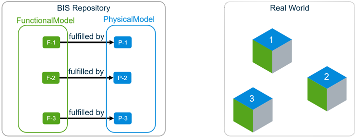 An Element in a different Model (see “P-0” below) models the car-as-a-whole as an “atomic” thing. The Model containing the “car part” Elements has a “breaks-down” relationship to the Element modeling the car-as-a-whole because it “breaks down” the Element (a simple, atomic model) into a finer-grained Model. Thus a BIS repository can cohesively model the car at two different Granularities—both as an “atomic” thing and as a fine-grained collection of parts.
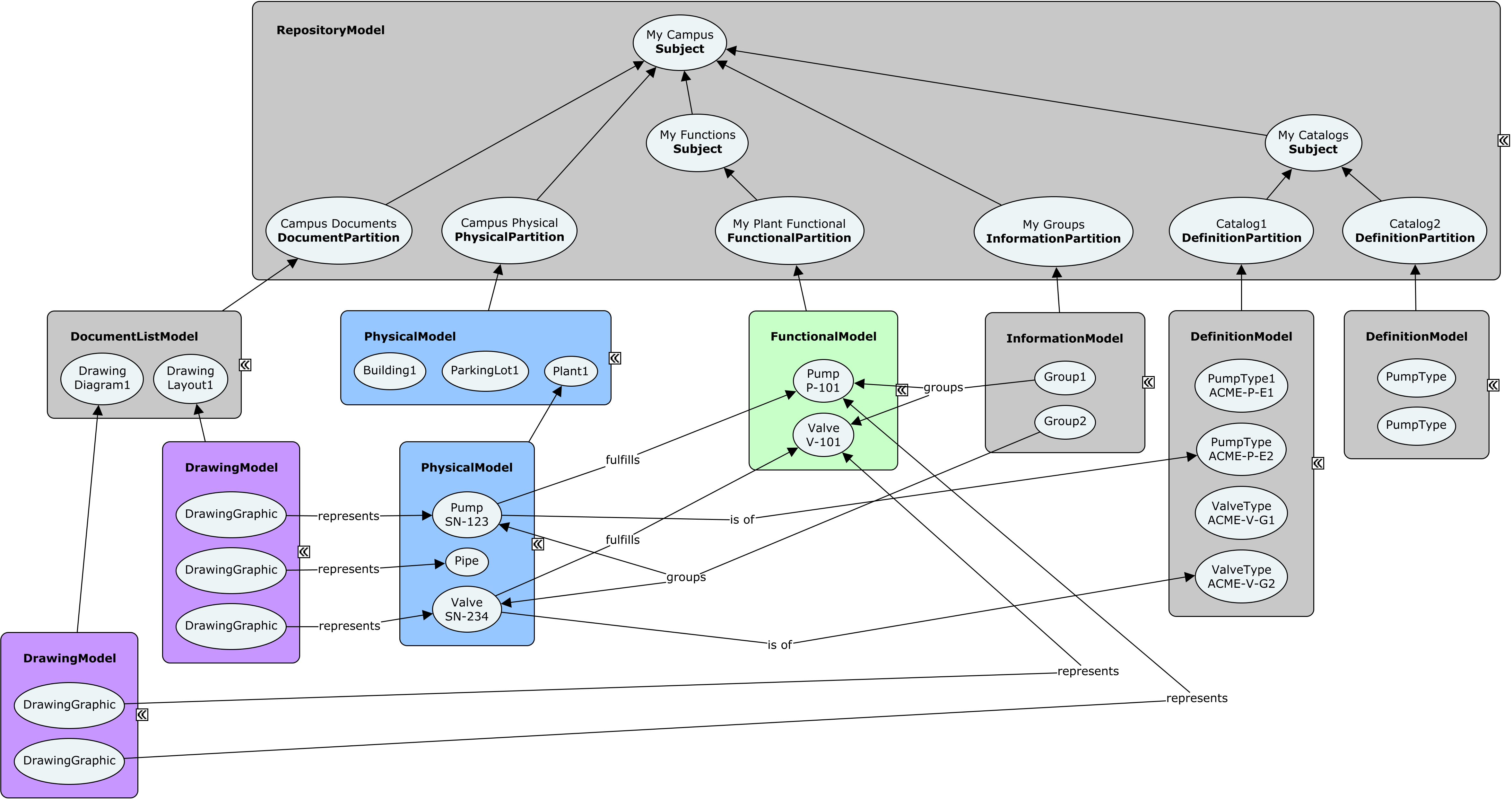
The Element modeling the car-as-a-whole is also in a Model. What Element is that Model breaking down? BIS escapes from infinite regression by defining a special RepositoryModel that is not required to “break down” some other Element. The RepositoryModel acts as the “Table of Contents” of the BIS Repository. It contains a “Subject” Element that textually references the Object that the BIS Repository is about. The RepositoryModel also contains one or more InformationPartitionElements. Each declares a modeling Perspective used to model the Subject. Each Partition will be “broken down” by Models of the same Perspective, e.g. a PhysicalModel will “break down” a PhysicalPartition.
Relationships
There can be many different kinds of Relationships among Elements within a Model or spanning Models. The various specializations of the ElementHasChildElements relationship are particularly important—they implement parent-child/whole-part relationships among Elements. For example, if Object 1 is a Door, it might have DoorHardware as a Child.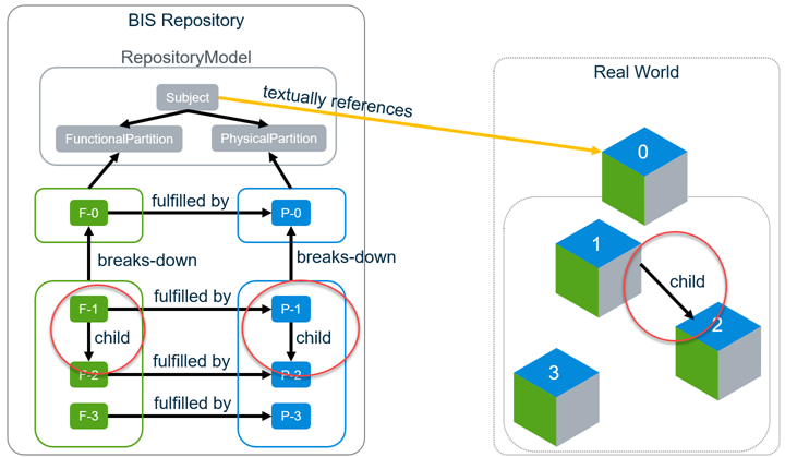
Thus, BIS supports two ways of modeling an Object and its parts:
- The class of Element modeling the Object can be “atomic” (not allowing any child Elements) and be broken-down as many Elements in a finer-grained “sub-Model”. BIS calls this a “sub-modeled Element”. The sub-modeled Element is intentionally redundant with the Elements in its sub-Model.
- The class of Element modeling the Object can allow “child” Elements, but then it is not allowed to be broken-down in a sub-Model. BIS calls this a “parent Element”—essentially modeling an Entity as an aggregate. A parent Element is not redundant with its child Elements.
At a minimum, a parent Element represents the identity of the aggregate. Optionally, it may model a part of the “substance” of the aggregate, in which case, its part of the “substance” should not be redundant with it child Elements. For example, the physical geometry of the DoorElement should not contain the geometry of the door hardware (assuming it has a DoorHardware child Element that contains that geometry.) You can model a “pure” assembly PhysicalElement by giving the parent Element no geometry and add child Elements that hold all of the geometry of the aggregate Entity.
These two rules imply that a given class of Element cannot be both sub-modeled and a parent. The schema author must choose one or the other (or choose to make the Element “strictly atomic”, meaning it can neither be sub-modeled nor have children.)
ElementAspect
ElementAspects are a flexible way to augment the properties of an Element. They are sets of properties that typically hold information needed only in certain contexts, e.g. during the construction phase or when we have a link to information about the modeled Entity in a different repository. ElementAspects are not individually identifiable (thus relationships cannot point to them), but they may be the “source” of a relationship pointing to an Element.
Identifiers
Elements have one primary identifier (ElementId) and hold two identifiers of the real-world Entity that the Element models: Code and FederationGuid.
ElementId is a 64-bit integer property that is the Element’s primary identifier and must be unique within the BIS Repository. Different implementations of BIS Repository manage this identifier differently.
The Code is a human-readable string identifier of the represented Entity. The Code encodes some business meaning. There are three Element properties related to the Code: CodeValue holds the Code, CodeSpec governs its encoding/decoding, and CodeScope defines the scope within which it is unique. The combination of the three code-related properties must be unique within the BIS repository and could be considered a secondary identifier of the Element.
The FederationGuid is optional but can be used to identify an Entity that is represented in many different repositories (BIS or otherwise).
UserLabel is an optional property of an Element that can be used as an informal name in the GUI, but it does not have to be unique. In some GUIs, if the UserLabel is null, the CodeValue will be used as a display label.
BIS Organization
Introduction
BIS is intended to be extended and revised over time. It is designed to be modular, so new problem spaces can be addressed incrementally as new Domains are added, layered on the core Schemas.
To anticipate this, the approach for BIS is to:
- Build on a solid theoretical foundation.
- Use a layered and compartmentalized organization.
- Have unifying organizational principals.
- Include a wide variety of perspectives and requirements in the development
- Vet the design with real use cases.
2 and #3 are discussed in this chapter.
A Family of Schemas
BIS will expand to include all disciplines that participate in designing, constructing, operating and maintaining infrastructure. A single schema that represented that huge scope would be very difficult to design, understand and maintain. BIS is consciously trying to avoid the problems associated with “the mother of all schemas”.
BIS is not a monolithic schema, but is modularized into a family of “domain” Schemas. Those Schemas are organized into a clear hierarchy, as shown in the following figure.
Schemas in any layer may refer to (be dependent upon) schemas in any lower layer. The layers of the schema hierarchy are intended to avoid circular dependencies while still allowing different domains to interoperate.
At the base of this hierarchy is the BisCore domain. BisCore defines the “fabric of the universe” and some key organizational strategies. All classes in other layers descend from classes in the BisCore allowing BIS-based software to understand – at least at some basic level – all BIS schemas, even BIS schemas it has never seen before.
Above the Core is the Common layer. This layer is where concepts that span multiple disciplines are defined. Examples of these concepts are “grid lines”, “building”, “bridge”, “linear referencing”, “schedule”, etc.. There will likely be many Common Domains.
The next 3 layers are divided horizontally by discipline (the “A”, “B” and “C”) and vertically by purpose (“Interop”, “Physical” and “Func/Analytical”):
- The Interop layer is for defining mix-ins or other concepts that other disciplines will need to implement or reference; an example might be an IElectricalLoad mix-in that allows other disciplines to define that instances of their classes have electrical power requirements.
- The Physical layer is for defining real-world physical entities and closely associated information.
- The Func/Analytical layer is for defining functional data (such as the process data behind P&ID drawings) and analytical data (such as the structural behavior data that is used to analyze a structure).
The top layer is for the App schemas. These schemas are intended to be very small, and contain no data that any other application would need or want to access. Most data that is currently considered application data will be found in the discipline or common layers.
BIS Compatibility Grades for Schemas
The conversion of products to use BIS Domain Schemas can occur incrementally, but an ecosystem of BIS-based infrastructure (including iModelHub and Design Review) is rapidly expanding. This creates a short-term need for BIS-based “compatibility” schemas that have not been as rigorously designed as true BIS schemas but allow usage and some level of interoperability with the BIS ecosystem. For this reason, a grading level for BIS schemas has been created:
- Grade A: True BIS schemas carefully designed for editing and interoperability
- Grade B: Either:
- Legacy “consensus” schemas (such as ISM), intelligently converted to BIS, or
- New BIS schemas, with one-way conversion to BIS in mind, but not intended for editing (native format).
- Grade C: Legacy schema, intelligently converted to follow basic BIS rules and patterns.
- Grade D: Legacy schema, auto-converted
Physical Backbone
A key organizational strategy for both the BIS schemas and the organization of data within BIS repositories is the “physical backbone”. For schema design the physical world is a unifying reality upon which all disciplines can agree when coming to a consensus on how to represent something in BIS.
Within a BIS repository, the representation of the physical world becomes the framework upon which we can organize other data. All data in BIS repositories is expected to be about or related to physical infrastructure. The physical infrastructure is modeled as a hierarchy and other non-physical information is stored relative to that hierarchy.
Fabric of the Universe
Introduction
This section briefly describes the few core concepts that form the foundation for all of BIS. All information in a BIS Repository is defined using Elements, ElementAspects, Models and relationships. We refer to these core concepts a “the fabric of the universe”.
BIS is expressed using the EC Information Modeling Language (aka “using ECSchemas”). However BIS imposes additional rules, naming conventions, and other restrictions. It is assumed that the reader is familiar with ECObjects. See ECSchema.
Most of the concepts below are defined as ECClasses in the “BisCore” domain schema, which has the alias “bis”, and thus we write “{ClassName}” to denote an ECClass defined in BisCore.
Elements
An Element is an object in the digital world that represents some entity in the real world, e.g. pumps, beams, contracts, companies, etc.). Elements are contained in Models. Elements are defined through ECProperties. Elements are the finest-grained object in BIS that can be individually identified and locked.
See Element Fundamentals for a more detailed discussion.
ElementAspects
An ElementAspect is a set of ECProperties that “belong” to a particular Element, but which have an independent lifecycle (they may come and go over the lifetime of the Element). ElementAspect instances are owned by a single Element; ElementAspects are never shared by more than one Element. An ElementAspect is considered part of the Element and therefore can not be the target of any “incoming” relationships (other than from the single Element that owns it.) There are ElementUniqueAspects that have a maximum of one instance per Element and ElementMultiAspects that may potentially have many instances per Element.
See ElementAspect Fundamentals for a more detailed discussion of ElementAspects.
Models
A Model is a container of Elements that provides a context (and a Modeling Perspective) for the contained Elements.
See Model Fundamentals for a more detailed discussion of Models.
Relationships
Various ECRelationship classes are defined in BisCore to relate Models, Elements and ElementAspects. See Relationship Fundamentals for a more detailed discussion of Relationships.
No other Data Types
All BIS information is defined using the Element, ElementAspect, Model classes or by using relationships. BIS domain schemas (other than BisCore) can only define classes that (directly or indirectly) subclass classes defined in the BisCore domain.
Element Fundamentals
A BIS Element represents an entity in the real world, e.g. pumps, beams, contracts, companies, processes, requirements, documents, persons, etc.
BIS Element Properties
The properties of an element are defined in its Schema. Every Element in BIS derives from the Element class. This section describes the properties of the Element class, and therefore the properties that every Element in an iModel has.
CodeSpec
See CodeSpec
CodeScope
See CodeScope
CodeValue
See CodeValue
FederationGuid
Every BIS Element has an optional 128 bit Globally Unique Identifier called FederationGuid. Generally it is intended that FederationGuid are assigned by external systems to federate Elements to their external meaning.
UserLabel
Every BIS Element has an optional UserLabel property, to provide an alias familiar to the user. The UserLabel may serve an alternate “friendlier” name in a GUI, e.g. the Room with CodeValue=”R-134” might have UserLabel=”The Big Kitchen” or UserLabel=”John’s Office”. There is no uniqueness constraint placed on the UserLabel.
With the exception of data conversion programs, the UserLabel is always left for the user to enter and is not programmatically generated.
JsonProperties
The JsonProperties member holds instance-specific ad hoc data on an Element in JSON format. It is a dictionary of key-value pairs, where the key is a namespace (see below) and the value is a JSON object. In this manner the JsonProperties member can hold any form and complexity of externally-defined (i.e. outside of BIS) data on any element.
To avoid conflicts in naming values, the top-level names for members of JsonProperties are reserved for namespaces. There is no registry for namespaces, so they should be chosen to be long and unique enough to avoid the possibility of collision (at least 8 characters.) By convention,
Note: all JSON property names, and therefore namespaces, are case sensitive.
The UserProps namespace
There is a reserved namespace of JsonProperties called UserProps. All values in the UserProps namespace are meant to be added by users, and application code should never store information there. Users should store their properties in names with their own name-scoping rules, such as a capitalized prefix to avoid conflicts. But since they know that only their data is held in the UserProps, they don’t need to worry about collisions with applications.
For example, an Element may have the following set of JsonProperties:
{"SLYSOFT_props": {"partType": "st-10","partName": "runner*144"},"IGASPEC_domFlow": {"max": 100,"min": 22},"UserProps": {"BTTE_vendorInfo": {"name": "Ace Manufacturing","contractId": "1032SW3"},"BTTE_approvals": {"reviewers": ["Tom", "Justine", "Nate"],"date": "2018-02-11","notes": ""}}}
Advantages and Disadvantages of JsonProperties
The largest advantage of JSON properties is that they do not require any schema or up-front work at all. The disadvantages of JSON properties are:
- No type-safety. There is no mechanism for controlling what is stored for any property name.
No required data. There is no mechanism for defining the requirement for certain properties to be defined.
Elements and Models
Each Element lives in a single Model. That Model contains and owns the Element. Models cannot be deleted unless all of their Elements are first deleted. Models provide context and scope for their Elements.
Every Model models (breaks down or describes) some Element. This is the basic building block of the Information Hierarchy, which is a key principle of BIS and supports modeling of reality from multiple perspectives and multiple granularities in a single Repository. It also results in a coherent and predictable structure in every BIS Repository, where all information is traceable to a single Root Subject for the entire BIS Repository.
There is one exception to the “Every Model models an Element” rule: There is exactly one RepositoryModel in every BIS Repository which does not Model another Element (at least not another Element in the same BIS Repository). This RepositoryModel is at the top of the Model/Element Information Hierarchy.ElementIds in iModels
When stored in an iModel, Elements also have a unique 64-bit local identifier, called an ElementId. ElementId is generated when new Elements are created by storing the BriefcaseId in the high 24 bits, with the next-available sequence number in the lower 40 bits. This allows new Elements to be created in any Briefcase without fear of ElementId collision.
Elements and Child Elements
An Element may have child Elements. Both the parent and the children must live in the same Model. The parent-child relationship implies ownership and cascading deletes. This is discussed more in the Assemblies section below.
Core Element Classes
These are subclasses of Element defined in the BIS core from which all other Element classes must descend:
GeometricElement
- InformationContentElement
- RoleElement

GeometricElement
GeometricElement represents any real world entity that we chose to model as inherently being geometric, such that it can be displayed graphically. This includes physical entities (such as electrical panels, beams and pumps) as well as drawing graphics (lines, arcs, circles, and annotations like text, plots, etc) in geometric context. Merely having a geometric property is not necessarily enough to merit an entity being represented by a GeometricElement; for example, a steel section shape is an DefinitionElement, not a GeometricElement.
The GeometricElement hierarchy defined in the BisCore schema is broken down as shown in the figure above.
Brief descriptions for the classes in the 2d branch are:
- GeometricElement2d – An Element that is inherently 2d in nature.
- GraphicalElement2d – A 2d Element that holds graphical information rather than geometry that has business meaning.
- DrawingGraphic – A 2d graphical Element that is intended to be placed on a Drawing.
Brief descriptions for the classes in the 3d branch are:
- GeometricElement3d – An Element that is inherently 3d in nature.
- GraphicalElement3d – A 3d Element that holds graphical information rather than geometry that has business meaning. Examples include text annotations or 3d bar charts. Instances of GraphicalElement3d are typically positioned for whitespace reasons since they are not tied to real-world 3d space.
- SpatialElement – An Element representing an entity that exists in and is relevant to real-world 3d space.
- PhysicalElement – A SpatialElement representing a real physical entity, i.e. one that has mass.
SpatialLocationElement – A SpatialElement representing some defined point, curve, surface, or volume in the real world. Spatial locations are not physical, and have no mass. Examples include a property line, a zoning envelope, an alignment, or a gridline.
InformationContentElement
An InformationContentElement is an Element that exists to carry and track information. Information Elements are inherently non-geometric and cannot be graphically displayed, but can contain geometric properties (for definition or specification purposes).
Examples include:A document
- A shared definition
- A requirement
- A specification
- An information record

RoleElement
Roles play a vital role (pun intended) in the ability of BIS to break down application-specific domain silos into pieces that allow common information to be shared and leveraged.
Use person/lawyer/father/son example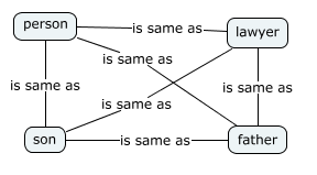
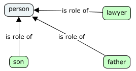
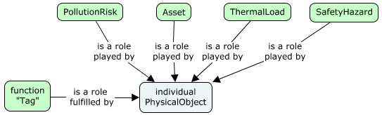
Roles are linked to each other through the PhysicalElement.
Each role may include some redundant information, but should generally share the physical form and properties of the PhysicalElement.
In our virtual world, roles can get “out of sync” with the PhysicalElements, and can even exist without the corresponding PhysicalElement existing. These out of sync cases often represent incomplete work (the P&ID has changed, but the 3d model has not yet been updated to reflect the changes), but sometimes reflect a long-term condition (the vehicle role is modeled in the asset management system, but there is no need to create the physical model of the truck).
Example of Element Type Usage

Assemblies
An Element can optionally have a parent Element. Parent Elements must be in the same Model as their children. A hierarchy of Elements can be created through these parent-child relationships (note: all the Elements in a hierarchy will reside in the same Model.) An Element that is a parent, can be considered to assemble its children, and collectively they are termed an Assembly. Assemblies can nest. Circular networks of parent-child relationship are not allowed.
Assemblies imply ownership and cascading deletes. When a parent Element is deleted, all of its children are deleted as well.
Assemblies tend to follow three patterns:
- The assembly is purely an aggregation; the primary role of the parent is to group the children together (example: a rebar cage collects various reinforcing bars together)
- The assembly is an elaboration; properties (or other information) in the parent allow the children to be generated (example: a pipe support generates a pipe clamp, a beam clamp and a threaded rod)
- The assembly is an item with modifications; the parent defines a base that the children modify (example: a BeamCope modifies a Beam).
As an Element can only have a single parent, it is important that domains and applications coordinate to ensure there is no conflict over which parent an Element should have. The best general rule to coordinate parenthood is that the domain author determines which Elements (if any) can be parents of its Elements.
Elements classes will generally fall into four categories:
- The Element can have any or no parents (example: Bolt).
- The Element cannot have a parent
- The Element can only have a parent of a particular class.
- The Element always has a parent, but there is little restraint on the class of the parent (example: Hole)
When designing assemblies, care must be taken to avoid double-counting.
See also the IParentElement and ISubModeledElement section below.
IParentElement and ISubModeledElement
This section tries not to repeat the material in Model Fundamentals and Information Hierarchy. If you have questions about how Elements breakdown into Models, you may want to skim those articles.
There are two mixins that declare and define key behaviors of an Element:
- IParentElement – this Element can be a parent Element
- ISubModeledElement – this Element can have an associated breakdown Model
The Element class does not include either of these interfaces, so by default no Element can have children or can be broken down into a Model. Many Elements have no need for child Elements or breakdown Models and will therefore use neither of these interfaces. A Bolt class is a example of a class that requires neither.
These mixins are expected to be mutually-exclusive. No class that implements IParentElement will also implement ISubModeledElement. The reason these two interfaces are considered mutually-exclusive is that the two concepts (having children and having a model) are both means of breaking down something into more detail; using two different breakdown methods simultaneously could result in confusion and double-counting.
Parent-Child Relationships
All Element parent-child relationships descend from ElementOwnsChildElements, which should not be used directly. There are specializations (subclasses) of the ElementOwnsChildElements relationship that clarify the relationship of the parent and child. Examples include:
- PhysicalElementEAssemblesElements – used to indicate that the child Elements are aggregated into the parent Element, whose geometry is entirely an aggregation.
- ElementEncapsulatesChildElements – used when the child Elements represent internal data that is not typically exposed to user or useful outside of the parent Element’s context.
- SubjectOwnsSubjects, SubjectOwnsPartitionElements - these relationships are used to constrain the set of Elements that are valid children of a Subject Element.
Groups
While parent-child relationships are of embedding strength and imply exclusive ownership, grouping relationships are of referencing strength and imply non-exclusive membership.
The grouping technique will vary depending on whether grouping a collection of member Elements is:
- The primary role of the Element or
- A secondary role of the Element.
In the first case, the ElementGroupsMembers relationship is used to relate group members to a GroupInformationElement that stands in for the group overall. A GroupInformationElement has no other reason to exist other than for grouping.
In the second case, a standard 1:N relationship can be used and grouping is implied. The grouping Element in this case would be valuable and exist whether or not it has members.
Element Codes
A Code is a human-readable string identifier of the real-world entity that an Element represents.
A Code conveys information to people and programs that understand the structure of the string and are therefore able to decode it.
Different domains and organizations have different ways of encoding business information into the Code, which they can express as Code Specifications.
CodeValue Property
Each Element has a (nullable) CodeValue string property that holds its Code.
When present, a CodeValue should be a human-understandable string.
Examples uses for Code
- Asset Tracking Number
- Tag Number
- Serial Number
- VIN Number
- Social Security Number
- Document Tracking Number
- Contract Number
- Project Number
- RFID
- Door Number
- Room Number
- Etc.
When the identified entity is physical in nature, it will often have its code physically affixed to it (as in the VIN Number on a car or the Manufacturer’s Serial Number on an instrument). When the identified entity is non-physical, it may have its code semi-permanently attached to a related physical entity. For example, a physical valve will have its serial number permanently affixed to it. The “Tag Number” of the “function” that the valve is performing in the process is stamped onto a “Tag” attached to the valve with a wire. If the valve is replaced with a new one (with a new serial number) the Tag holding function’s “Tag Number” will be moved to the new valve.
Example misuses of Code
- A Guid is not human-understandable and does not encode business meaning, so should not be used as a CodeValue—FederationGuid fulfills that purpose.
- A Hash should not be used as a CodeValue for the same reasons as above.
A CodeValue that is hundreds of characters long would also be very difficult for a human to understand, so should be avoided. In fact, a code management service may enforce a hard limit on the length of the CodeValue. For example, iModelHub currently has a hard limit of 350 characters.
CodeSpec
A CodeSpec (aka Code Specification) names and specifies a new classification for Codes. A CodeSpec also captures the rules for encoding and decoding significant business information into and from a Code. For example, the Codes for ViewDefinitions and the Codes for Equipment have different encoding rules and uniqueness constraints, so would each have a separate CodeSpec.
Typically, a CodeSpec has a strong correlation with a branch of the Element class hierarchy and is often named after an abstract base class that defines the starting point of that branch. It is common for all subclasses (direct or indirect) descending from that base class to share the same CodeSpec. For example, the standard CodeSpec called “bis:ViewDefinition” helps ensure unique names for all subclasses of the BisCore:ViewDefinition Element class. Configuration can define the association between Element class and CodeSpec so that a shared service (e.g. ‘Identification Code Service’) can be used to generate and validate Codes. The CodeSpec can also dictate that Codes for instances of the Element class should be null. This is appropriate when the modeled real-world entities don’t have a meaningful real-world identifier (e.g. a piece of baseboard, a pile of dirt, an average bolt).
Note: To ensure unique CodeSpec names, a namespace (often the alias of a schema) should be used as demonstrated with the standard “bis:ViewDefinition” CodeSpec.CodeSpec Property
Each Element has a CodeSpec navigation property relating it to a CodeSpec that governs its Code. A single BIS Repository (e.g. an iModel) is expected to use many Code Specifications—different classes of Elements can have different coding conventions.
CodeScope Property
Each Element has a CodeScope navigation property that points to another Element that provides the uniqueness scope for its Code. The ‘scoping’ Element can represent the repository as a whole, a model, an assembly, etc. The CodeSpec specifies the types of elements that can be used as a CodeScope. The most common types are:
Repository - CodeValues are unique across an entire repository.
- Model - CodeValues are unique within a Model.
- ParentElement - CodeValues are unique among children with the same parent.
- RelatedElement - CodeValues are unique across the set related to the same element.
For example, a Floor Code (like “1” or “2”) must be unique within a Building, but is not unique across Buildings. In this example, the Building instance is providing the CodeScope for the Floor.
Note: The ‘scoping’ Element could also represent some entity with a scope that is greater than the current BIS Repository. In this case, uniqueness within that scope can only be enforced by an external ‘Identification Code Service’.
Uniqueness within a BIS Repository
For a given Element, the combination of it CodeSpec, CodeScope, and CodeValue properties must be unique within the BIS repository. All null values are considered to be unique.
ElementAspect Fundamentals
Introduction
ElementAspects are EC classes, typically with EC properties defined for them. ElementAspects are generally used for creating optional sets of properties.
ElementAspects have a special relationship with Elements. Every ElementAspect instance is associated (through an EC relationship) to exactly one Element instance. ElementAspect instances are never shared among Element instances. An Element owns its ElementAspects; if the Element is deleted its ElementAspects are also deleted.
Core ElementAspect Types
There are three core ElementAspect classes in this class hierarchy:
- ElementAspect
- ElementUniqueAspect
- ElementMultiAspect
All three of these classes are abstract and therefore never instantiated. ElementAspect is not expected to ever have more than the two subclasses shown here. There are and will be many subclasses of ElementUniqueAspect and ElementMultiAspect.
ElementUniqueAspect
ElementUniqueAspect is used as a base class when there may be zero or one (but never more than one) ElementAspect of the exact same ECClass owned by an individual Element.
The relationship ElementOwnsUniqueAspect is used to connect an Element to an ElementUniqueAspect.
ElementMultiAspect
ElementMultiAspect is used as a base class when there may be zero, one, or more ElementAspects of the same ECClass owned by an individual Element.
The relationship ElementOwnsMultiAspects is used to connect an Element to its ElementMultiAspects.
ElementAspects and Identity
ElementAspects primarily derive their identities from the Element which owns the ElementAspect.
For an ElementUniqueAspect, the combination of subclass and the Element identity uniquely identifies the ElementUniqueAspect.
For an ElementMultiAspect, the combination of subclass and the Element identity identifies a list of ElementMultiAspects. Every ElementMultiAspect also has a private Id if an individual ElementMultiAspect instance has to be referenced.
ElementAspects and Relationships
ElementOwnsUniqueAspect and ElementOwnsMultiAspects relationships are used to define the ownership of ElementAspects by Elements, but what about other ElementAspect relationships? The only other relationships that ElementAspects may have are “outward” relationships that effectively map to a single foreign key in the ElementAspect. These “outward” relationships cannot be traversed to the ElementAspect.
For example, A Fireproofing ElementAspect might have a Thickness property and a relationship to a FireproofingMaterial. As the relationship is “outward”, it would not be possible to find all the Fireproofing aspects that are related to a FireproofingMaterial without searching.
General behaviors and uses of BIS relationships are discussed in Relationship Fundamentals.
Common Strategies Involving ElementAspects
Because ElementAspects are ECClasses, they have a fixed schema. This gives them the same first class reporting functionality as with Elements. ElementAspects are often used when the same set of properties needs to be stored for Elements that live in different parts of the class hierarchy. However, if the data is more ad-hoc, then Element JsonProperties are probably more appropriate.
Mixins
Mixins play a key role in supporting cross-discipline coordination in BIS.
A Mixin is an abstract EC class that follows a strict set of requirements that are intended to provide the desired functionality while minimizing confusion and implementation costs. The requirements may be relaxed in the future if use cases supporting relaxation are found. The requirements for a Mixin class are as follows:
- Mixins are abstract EC Entity classes.
- Mixins may have 0 or 1 base classes. If there is a base class, it must be another Mixin.
- Mixins must have the IsMixin custom attribute defined.
- Mixins may not override an inherited property.
The Mixin custom attribute is defined as follows:
<ECCustomAttributeClass typeName="IsMixin" description="Applied to abstract ECEntityClasses which serve as secondary base classes for normal ECEntityClasses." displayLabel="Is Mixin" appliesTo="EntityClass" modifier="Sealed" ><ECProperty propertyName="AppliesToEntityClass" typeName="string" description="This mixin may only be applied to entity classes which derive from is class. Class Name should be fully specified as 'alias:ClassName'" /></ECCustomAttributeClass>
A class incorporates a Mixin by declaring the Mixin class as a base class. An Mixin is never the first base class listed (that position is reserved for the “real” base class). A class may implement multiple Mixins, but may only have one “real” base class. Classes that incorporate Mixins must also follow strict rules:
- The incorporating class must descend from the AppliesToEntityClass defined in the IsMixin custom attribute.
- The implementing class must not have an EC property (including inherited properties) that has the same name as a Mixin property.
Mixins can be used as relationship endpoints.
By convention, interface-like Mixin classes have class names with an “I” prefix. Interface-like Mixins satisfy one or more of the following criteria:
- The Mixin is expected to be used as a relationship endpoint.
- The Mixin is expected to be used by code or logic that will not know which class has incorporated the Mixin.
- The Mixin has no properties and is used as a marker class.
Model Fundamentals
A Model is a container that owns a collection of Elements. Every Element is contained by exactly one Model as defined by the ModelContainsElements relationship. Models help organize the overall contents of the repository as there is a separate container for each collection of Elements. The Model contents are driven by:
- The Model subclass
- Model specializations may limit the types of Elements that can be contained.
- The granularity or level of detail
- The object as a whole vs. a more detailed breakdown of it
- User preferences
- Some users may organize by spatial location (east wing vs. west wing) while others may organize by discipline (building vs. civil)
- Domain rules
- Some rules are enforced by code and are not customizable by users
Core Model Types
| Model subclass | Type of Elements contained | | —- | —- | | PhysicalModel | PhysicalElements and SpatialLocationElements | | SpatialLocationModel | SpatialLocationElements | | DrawingModel | GeometricElement2d elements | | DefinitionModel | DefinitionElements | | InformationRecordModel | InformationRecordElements | | GroupInformationModel | GroupInformationElements | | DocumentListModel | Document elements |
- Some rules are enforced by code and are not customizable by users
Model Identity
Models are also a key building block of the information hierarchy within a BIS repository. Looking down the information hierarchy, Models are collections of Elements. Looking up the information hierarchy, Models are more detail about an Element from a higher level. This higher-level Element is known as the modeled element. The modeled element is what gives a Model its identity. The value of the model’s Id matches the value of the modeled element’s Id. The Model is related to its modeled Element via the ModelModelsElement relationship. Also, a Model does not store a name of its own. Instead, its name comes from the CodeValue of its modeled element.
See Information Hierarchy for more details.
Relationship Fundamentals
Introduction
Relationships are one of the main building blocks of BIS. They are used to define associations among entities. More specifically, BIS depends heavily upon EC relationships to define its conceptual schema. With the exception of relationships used by navigation properties, all relationships in BIS must inherit from some relationship in the core. The most commonly used core relationships are:
- ElementOwnsChildElements
- ElementRefersToElements
- ElementOwnsUniqueAspect / ElementOwnsMultiAspects
-
Relationship Inheritance in BIS
Relationship inheritance is supported in BIS, but is tightly constrained. All relationships must be abstract, concrete or sealed:
Abstract relationship classes can never be instantiated. ElementRefersToElements is an example of an abstract relationship. It must be subclassed to be instantiated.
- Concrete relationship classes can be inherited from and can be instantiated. ElementOwnsUniqueAspect is an example of a Concrete relationship.
- Sealed relationship classes can never be inherited from. ModelContainsElements is an example of a sealed relationship.
In addition, all BIS relationships, excepting the ones used to define new navigation properties, must inherit (directly or indirectly) from a relationship in the BIS core.
Inheriting relationships must “narrow” the relationship:
- Equal or more-specific sources and targets.
- Equal or more-restrictive multiplicity.
- The polymorphic flag may be changed from true to false but not false to true.
Strength and direction must be the same.
Relationship Strength
The strength of a relationship defines the lifetime of objects on its target end point and therefore, it must be specified. The two accepted strengths in BIS are:
Embedding: Objects control the lifetime of some other objects, considered their children. That is, when a parent object is deleted, related child objects will be deleted as well. ElementOwnsChildElements is an example of an embedding relationship.
- Referencing: Objects point to some other objects without controlling their lifetime. ElementRefersToElements is an example of a referencing relationship.
The strength direction of a relationship specifies the orientation in which the strength is interpreted. That is, in a Forward relationship, its strength is enforced from Source to Target. Whereas in a Backward relationship, its strength is enforced from Target to Source. If a relationship does not specify a strength direction, Forward is assumed by default.
ElementOwnsChildElements is an example of a Forward relationship. ModelModelsElement is an example of a Backward relationship since its embedding strength is enforced from an Element to its Model.
In most cases, both the strength and direction of a relationship are already defined by base relationships defined at the core. These settings cannot be modified or overridden by subclasses.
Relationship multiplicity
Each endpoint of a relationship must define a multiplicity, they together define the cardinality of the relationship. The multiplicity format specifies the number of times an endpoint may be used in this relationship. It is defined using the format (
Example
<ECRelationshipClass typeName="ElementOwnsChildElements" strength="embedding" modifier="None"><Source multiplicity="(0..1)" roleLabel="owns child" polymorphic="true"><Class class="Element"/></Source><Target multiplicity="(0..*)" roleLabel="is owned by parent" polymorphic="true"><Class class="Element"/></Target></ECRelationshipClass>
The ElementOwnsChildElements relationship defines the following constraints:
- The parent Element (Source) may own any number of child Elements (Target). Determined by the Target multiplicity.
- The parent Element controls the lifetime of the child Elements, so deleting the parent deletes the children. Determined by the relationship strength. NOTE: Direction is assumed to be from Source to Target because none is specified.
- An Element may only have one parent. Determined by the Source multiplicity.
Relationships that derive from ElementOwnsChildElements may make the following changes
- Make the relationship mandatory for the parent by changing the target multiplicity to (1..*).
- Make the relationship mandatory for the child by changing the source multiplicity to (1..1).
- Limit the parent to only one child by changing the target multiplicity to (0..1).
- Limit either endpoint to a class more specialized than Element by changing the Class constraint to an entity class which derives from Element.
- Limit either endpoint to a specific class by changing the polymorphic flag to false.
Make the relationship abstract or sealed by changing the modifier to Abstract or Sealed.
Supported Relationship Capabilities
Relationships in BIS are restricted more than in plain EC.
Relationship inheritance is strictly limited, as discussed previously. A relationship may only have a single base class.
- Relationship end points must be either entity classes or link-table relationships.
- Relationship end points must have a single constraint class.
- Aspects are only allowed as the source of relationships behind navigational properties, or as the target of element-owns-aspect relationships.
Plain EC supports Holding as an additional type of relationship strength, but it is not supported by BIS.
Implementation Details Limiting Relationship Flexibility
For the purposes of optimized performance of BIS applications using iModel technology, the full power of relationships is not available in all cases. To understand these limitations, it helps to understand the 2 implementations of relationships in iModel databases.
iModel-specific implications of Relationship Inheritance
If the relationship is not sealed (can be subclassed) then an additional database column is required to store the relationship class Id. This is the case of the ElementOwnsChildElements relationship which is expected to be subclassed.
Sealed relationships with no base class and no subclasses will not need an extra column to store the relationship class Id. This is the case of the ModelContainsElements relationship, which is marked as sealed with no base class.
Link Table
In iModel databases, there is a single link table (bis_ElementRefersToElements) that supports all relationships between elements with either of these requirements:
Both the source and the target have unconstrained multiplicity (..)
- The relationship can contain properties.
All relationships that have either of these requirements must inherit from the ElementRefersToElements relationship in the BIS Core schema.
Note that neither Models nor Aspects may be the source nor target of relationships in the link table, and therefore Models and Aspects cannot be involved in relationships with properties or relationships with (..) multiplicity.
An example of a relationship stored in the Link Table is the ElementGroupsMembers relationship that has the unconstrained multiplicity (..).
Navigation Properties
Navigation Properties are analogous to foreign keys but exposed as EC properties and EC relationships. As an implementation detail for iModels, their relationship storage (and presentation) strategy enables access via a foreign key of the object being pointed to in the object pointing to it. The side of the relationship stored in the foreign key must have a multiplicity of (0..1) or (1..1). The Navigation property is always defined in the base relationship and never via subclassing.
For sealed Navigation Properties, a single foreign key database column is used to store the relationship. An example of the use of a navigation property for a sealed relationship is the ModelContainsElements relationship. The relationship has a multiplicity of (1..1) on the source side (every Element must be in a Model), so the relationship is stored in the Model navigation property of the target Element.
Regarding subclassable Navigation Property relationships, ElementOwnsChildElements relationship can be reviewed as an example. This relationship is not sealed (it can be, and often is, subclassed) so two database columns are used to store it. The relationship has a multiplicity of (0..1) on the source side (every Element has 0 or 1 parent), so the relationship is stored in the Parent navigation property of the target.
Lastly, Navigation Properties can also be defined for Link table relationships. In this case, the link table relationship is specified as an end point of the Navigation Property relationship.
Schemas (“Domains”)
Introduction
Domain is a synonym for BIS ECSchema. Domains define the data types for a naturally coherent and limited subject matter. This approach aims to avoid problems and complexities associated with understanding and managing monolithic or very large schemas. It highly depends on coordination and cooperation among multiple BIS domain designers so each sharable concept needed by BIS applications find its appropriate home (i.e. domain) where it will be managed and maintained.
With Domains being the main concept in BIS behind how the world is divided in, and each domain being small enough to have a clear scope and owner, BIS can also be thought as a modular family of “domain” schemas.
A Layered Approach
Domains are organized into layers based on how generic or specialized the subject matter of the ECSchema in a domain is. The most generic ECSchema in BIS, which lies at the base of this hierarchy – depicted in the figure below – is BisCore.
Schemas in any layer may be dependent upon schemas in any lower layer. The layers of the schema hierarchy are intended to avoid circular dependencies while still allowing different domains to interoperate.
The BisCore layer
BisCore defines the core ECClasses and organizational strategies that all other data types in other domains must follow. Classes such as Model, Element and UniqueAspect are in the BisCore.
The Common layer
The next layer in the BIS family of ECSchemas above “Core” is “Common”. That is where broad concepts applicable to multiple disciplines are defined. As an example, a Building “Common” schema may include concepts like stories, but not details of architecture (such as Windows), or structure (such as beams).
The three layers above “Common” specialize on a single discipline (in the figure above, sharing the same initial letter), while differentiating in their purpose: “Interoperability”, “Physical” and “Functional/Analytical”.
The Interoperability layer
The “Interoperability” layer aims to contain concepts that other disciplines will need to implement or reference. As an example, an IElectricalLoad mixin defined by the electrical discipline may allow other disciplines to define required electrical service (pumps, elevators, server rooms, etc.).
The Physical layer
“Physical” and “Functional/Analytical” domains model a particular discipline from different perspectives.
The Physical layer defines real-world physical entities and closely associated information. Classes such as Pump, Pipe or Roadway are in the Physical layer.
The Functional/Analytical layer
This layer defines data types for functional or analytical data towards enabling various schematics and simulations.
The Application Layer
The top layer is for any needed application schema. These schemas are intended to be very small, and contain no data that any other application would need to access. Most data that is currently considered application data will probably be found in the discipline or common layers.
Physical Backbone
A key organizational strategy for both the BIS schemas and the organization of data within BIS repositories is the “physical backbone”. For schema design the physical world is a unifying reality upon which all disciplines can agree when coming to a consensus on how to represent something in BIS.
Within a BIS repository, the representation of the physical world becomes the framework upon which we can organize other data. All data in BIS repositories is expected to be about or related to physical infrastructure. The physical infrastructure is modeled as a hierarchy and other non-physical information (e.g. Functional or Analytical perspectives) is stored relative to that hierarchy. However, it is expected that in some workflows the physical infrastructure appears after other non-physical data is modeled. Thus, the concept of a “physical backbone”, albeit not being mandatory from the start of a BIS repository, it should drive the design of the various domains in a discipline.
Domain Handlers
The BIS schema for a Domain is expected to be useful to a wide variety of clients, designed with the mindset that multiple products, or other domains if needed, will make use of them. Furthermore, as part of the implementation of a BIS Domain, a cross-platform C++ component – usually referred to as a “Domain Handler” – is expected to be in place, representing code that understands the BIS ECSchema the Domain is about, is able to read and modify its data in a coherent manner, as well as exposing public APIs providing special functionality to make working with its ECSchema easier and less error-prone.
Lifecycle Considerations
Disciplines that will be using BIS usually focus on the entire lifecycle of infrastructure assets. That is, conceptual/detailed design, construction, operations and maintenance lifecycle phases. BIS, at its core, does not intend to break up schemas further into lifecycle phases, but rather be agnostic of them. Thus, a domain BIS ECSchema should be designed so that it can accommodate data at various phases.The quality and/or detail of data for any BIS concept modeled by an ECSchema should evolve as it “flows” through lifecycle phases. No import/export workflows shall be needed.
Designing BIS schemas backwards (i.e. understanding concepts needed for Operations and Maintenance first, while leaving Conceptual Design last) may help to identify all needed pieces towards achieving a schema that works for the entire lifecycle of the infrastructure of interest.
Example
Taking Road & Rail disciplines as a example, the following figure depicts how they can be divided into various BIS domains.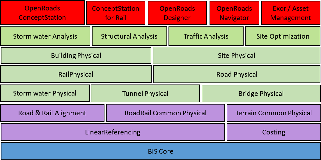
At the lowest level, BisCore continues to be most generic domain, layout the framework and foundation for all BIS domains.
Next layer up – Common – domains shared with disciplines other than Road & Rail can be found. Those include domains such as Linear-Referencing, Costing and physical Storm water Drainage structures.
Above Common, discipline-specific layers are introduced. In the case of Road & Rail, domains that introduce fundamental pieces such as Alignments – based on Linear-Referencing – and Physical Terrain can be found. These in turn serve as the foundation for Physical domains focusing on different structures common in Road and Railways, such as Bridges, Tunnels and Pathways in general.
Other domains in Road & Rail disciplines focusing on Analytical perspectives included in the figure above include: Structural Analysis (applicable to bridges and tunnels), Traffic Analysis and Storm water Analysis (Hydraulic and Hydraulic simulations).
Additionally, concepts defined in these Road & Rail domains are needed in other disciplines, such as Site and Building – Physical as well as analytical, such as for Site optimization – calling for references from these other domains into the appropriate Road & Rail domains depicted below.
Lastly, several Civil applications can be built on top of all these Road & Rail domains. These Civil applications may focus on specific assets and lifecycle phases in the Road & Rail disciplines. However, BIS ECSchemas referenced by them are expected to be useful across the entire lifecycle of assets in the Road & Rail disciplines.
Information Hierarchy
The information in a BIS repository is arranged in a hierarchy that is governed by rules. Some of the rules are explicitly defined by the schemas, and other rules require the applications that are creating data to follow standards.
The hierarchies in BIS repositories are intended to facilitate both human and software comprehension of the data.
Hierarchy Constructs
As was explained in Model Fundamentals, there are only three mechanisms available in BIS to create a hierarchy:
- A Model can contain Elements
- An Element can own child Elements
- An Element can be modeled by (broken down into more detail by) a SubModel
Each of these three mechanism is intended to be used in specific circumstances which are explained in this chapter.
Model Contains Elements
A Model is a container for Elements. Models are a way to subdivide and organize the overall repository. Each Element is contained by exactly 1 Model as defined by the ModelContainsElements relationship.
Element Owns Child Elements
An Element can own child Elements. This is useful for modeling assembly relationships or for modeling cases where one Element exclusively controls the lifetime of other Elements. An Element can have 0 or 1 parent Elements as defined by the ElementOwnsChildElements relationship. An Element without a parent is considered a top-level Element. An Element with a parent is considered a child Element. These hierarchies can go N levels deep, which means that an Element can be both a parent and a child.
Model Models Element
A Model is more detail about an Element from a higher level in the information hierarchy. A Model is about exactly 1 Element as defined by the ModelModelsElement relationship. From the Model’s perspective, this higher-level Element is known as the modeled element. From the Element’s perspective, the lower-level Model is knows as the SubModel. The SubModel term is just a way to refer to a relative position in the information hierarchy. There is no special class for a SubModel, only the standard Model subclasses.
For example, a DrawingModel breaks down a Drawing Element and contains the DrawingGraphic Elements that are the details of the overall drawing.
Top of the World
The top of the information hierarchy is strictly controlled and is very similar in all BIS repositories. Its contents are explained in Top of the World
Example Information Hierarchy
Modeling Perspectives
As discussed in Modeling with BIS, objects in the real world can be thought about from different modeling perspectives. A modeling perspective is a way of conceptualizing the real world for a particular purpose. For example, a Sewer System can be thought about from many modeling perspectives:
- As a physical 3D reality with form, material and mass (the physical perspective).
- As a system for hydrological conveyance (an analytical perspective)
- As a set of components that require scheduled and emergency maintenance (a maintenance perspective)
As a load on a wastewater treatment facility that needs to have adequate capacity (a functional perspective)
Keeping Modeling Perspectives Segregated
Each modeling perspective simplifies objects in the real world in a different way; this requires different specialized data structures for each perspective. This is manifested in BIS classes as explained in the following section.
Each perspective’s data (InformationPartitionElements, Models, Elements, etc.) is segregated from other perspectives’ data in order to allow each perspective to be optimally organized. Relationships between the Elements of different perspectives are used to indicate that they are all modeling the same objects, just from different perspectives.Modeling Perspectives and BIS Class Hierarchy
Modeling perspectives are represented directly in the BIS class hierarchies as:
InformationPartitionElement subclasses
- Model subclasses
- Element subclasses
For every modeling perspective there is a corresponding InformationPartitionElement subclass and a Model subclass.
Modeling perspectives are also manifested in Element subclasses. Often there is an Element subclass that directly corresponds to a modeling perspective. Elements placed in a Model need to have a modeling perspective that is compatible with the Model.
Top of the World discusses InformationPartitionElements and Model Fundamentals discusses Models.
Modeling Perspective Consistency of Partitions, Models and Elements
As is described in Top of the World, for every Subject, there may be zero or more InformationPartitionElement child Elements. Each of those InformationPartitionElements is effectively a declaration of modeling perspective and starts a Model hierarchy that is of that the declared modeling perspective.
Each InformationPartitionElement breaks down into a Model that is of the same modeling perspective. That Model in turn contains only Elements of the same modeling perspective. Some of those Elements will have breakdown Models; the breakdown Models must be of the same modeling perspective as the Element they break down.
These modeling perspective rules enforce a minimum level of logical data consistency. For example, they prevent the placement of a physical fire hydrant Element into a section drawing Model.
Abstract, Concrete and Sealed Modeling Perspectives
Modeling Perspectives can be considered to be abstract, concrete, or sealed to correspond with the InformationPartitionElement and Model subclasses that implement them:
- An abstract modeling perspective is used only to logically group more-specialized perspectives and is implemented by abstract InformationPartitionElement and Model subclasses.
- A concrete modeling perspective is used directly to model reality and is implemented by concrete InformationPartitionElement and Model subclasses.
A sealed modeling perspective is a concrete modeling perspective that is not allowed to be further specialized. A sealed modeling perspective is implemented with sealed InformationPartitionElement and Model subclasses.
Standard Modeling Perspectives
It is not possible to predict all of the modeling perspectives that may eventually be needed in BIS. BIS does, however, provide a core set of modeling perspectives from which other modeling perspectives must derive.
The core modeling perspectives are:Geometric (abstract)
- Geometric2d (abstract)
- Graphical2d (abstract)
- Sheet (concrete)
- Drawing (concrete)
- SectionDrawing (concrete)
- Graphical2d (abstract)
- Geometric3d (abstract)
- Spatial (abstract)
- Analytical (abstract)
- SpatialLocation (concrete)
- Physical (sealed)
- WebMercator (concrete)
- Spatial (abstract)
- Geometric2d (abstract)
- Role (abstract)
- Functional (concrete)
- Information (abstract)
- GroupInformation (abstract)
- InformationRecord (concrete)
- Definition (concrete)
- (Repository) (sealed)
- Dictionary (sealed)
- DocumentList (concrete)
- Link (concrete)
If the need for a new core modeling perspective is discovered (none of the existing core modeling perspectives is appropriate as a parent perspective), new ones can be added.
Physical Modeling Perspective
The Physical modeling perspective views reality as objects with form, material(s) and mass in 3D space. The Physical modeling perspective merits special discussion as it plays such an important role in BIS.
There is one and only one Physical modeling perspective. The Physical modeling perspective is used and shared by most disciplines, just like the physical components of each discipline must co-exist in the same physical space. If there is one sewer pipe in reality, there can only be one physical representation of that sewer pipe.
The Physical modeling perspective cannot be “subclassed”. (For legacy reasons there are some subclasses of PhysicalModel in BIS schemas, but those subclasses are never used.)
See Physical Models and Elements for details of physical modeling.
Physical Backbone
The principle of a “physical backbone” in BIS states that the one thing that all disciplines can agree upon is physical reality, and thus the physical perspective should be the “touchstone” among other perspectives. Elements representing a non-physical perspective of a physical object will typically have a relationship to a PhysicalElement modeling the object from a Physical perspective.
Functional Modeling Perspectives
Functional modeling perspectives view reality as objects intended to perform a function. Often those objects are connected to form a functional system.
An example of a functional modeling perspective is viewing the interconnected components of a process plant as a system that performs a function.
See Functional Models and Elements for details of functional modeling.
Analytical Modeling Perspectives
The analytical modeling perspective views reality as objects in 3D space that participate in a phenomenon that can be analyzed.
An example of an analytical modeling perspective is thermal analysis of a building, where the components of the building have thermal properties and may be heat sources or sinks.
There are similarities between the Functional and Analytical perspectives. The primary difference between the two is that for the Analytical perspective, 3D locations are critical to the behavior.
Note that some analyses can be performed directly on the Physical Perspective data; these analyses do not require conceptually reality from a custom perspective.
See Analytical Models and Elements for details of analytical modeling.
Domains and Modeling Perspectives
A domain may or may not require a custom modeling perspective. The need for a custom modeling perspective corresponds to a need to model reality using concepts that are significantly different from other existing modeling perspectives.
Structural Steel Detailing is an example of a domain that does not require its own modeling perspective. That domain will require custom classes to represent the physical items that are important to it, but all of those items are viewed from the Physical modeling perspective. Structural Steel Detailing might also need some scheduling or costing information; that information is unlikely to require a custom modeling perspective, as costing and scheduling are common needs.
Hydraulic Analysis, on the other hand, does require a custom modeling perspective. This perspective will model reality as a system that transports and stores water. Reality will be simplified into a network of conduits and other items, with properties and relationships appropriate for hydraulic analysis.
Top of the World
BIS repositories have a strict hierarchical organization. This page describes the top of that hierarchy and how it functions as a table of contents for the repository as a whole. This table of contents consists of:
- RepositoryModel
- Subjects
-
RepositoryModel
Every BIS repository has exactly one RepositoryModel that defines the top of the hierarchy. Elements can be inserted into or updated within the RepositoryModel, but the RepositoryModel itself cannot be deleted.
The RepositoryModel is the only Model in a BIS repository that does not have a ModelModelsElement relationship and an “owning” ElementSubjects
Subjects are Elements that are used to identify things that the repository is about. The Subject class cannot be specialized (subclassed). The most important capabilities of Subject are:
It can have a UserLabel (inherited from Element)
- It can have a Description
- It can have child Subjects
- It can have child InformationPartitionElements
Subjects only exist in the RepositoryModel.
Every BIS repository has exactly one root Subject that describes what the repository as a whole is about.
- The root Subject - like all Subjects - is contained by the RepositoryModel.
- The root Subject has no parent element as it is the top of the Subject hierarchy.
- The root Subject can be updated, but it cannot be deleted.
Child Subjects (optional) can be introduced to further organize the contents of the repository.
- Child Subjects - like all Subjects - are contained by the RepositoryModel.
- Child Subjects have another Subject as a parent.
InformationPartitionElements
As discussed in Modeling Perspectives Subjects can be viewed and modeled from multiple modeling perspectives (physical, functional, analytical, etc.). InformationPartitionElements are used to “partition” a Subject into different modeling perspectives.
When it is determined that a Subject is to be modeled from a particular modeling perspective, an InformationPartitionElement of the appropriate modeling perspective is added as a child of the Subject. That InformationPartitionElement is the start of a Model hierarchy representing the modeling perspective. The InformationPartitionElement is immediately broken down into a Model of the same modeling perspective.
It is possible for a Subject to have multiple InformationPartitionElements of the same modeling perspective. An example of this would be having two StructuralAnalyticalPartitions for a building (the Subject) that has an isolation joint that divides the building into two separate structures.
InformationPartitionElements always have a parent Subject and are never used outside of the RepositoryModel.
The Single Responsible-Party Principle (SRPP)
Throughout the information lifecycle of infrastructure engineering, the responsibility for information is a key concern. These responsibilities influence the organization of all relevant information repositories, including BIS Repositories.
For this reason, it is helpful when we can identify a single responsible-party for any piece of information in a BIS Repository. To facilitate the identification of the responsible party for information, all domain authors and developers should follow these two rules:
- A Model should have a single responsible-party at any given point in time.
- Sub-modeled Elements may have a different responsible-party than their sub-Model.
The first rule facilitates mapping of Models to ISO 19650 “information containers”, among other practical considerations. The second rule allows a responsible-party to delegate responsibility for the detailed sub-modeling of an Element to another party.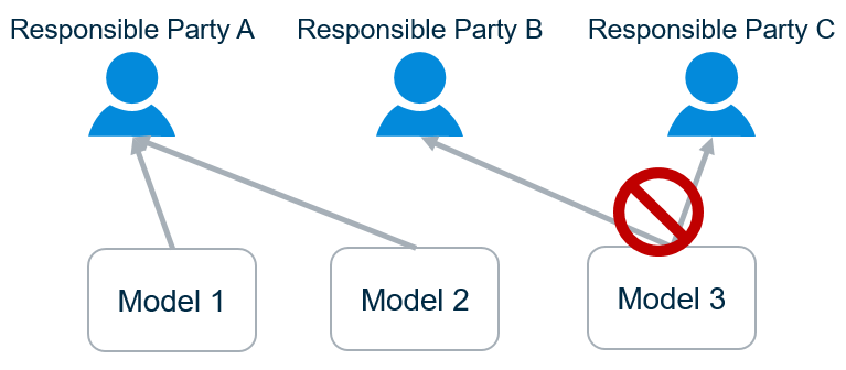
The responsible-parties may be organizations or individuals. Because there are typically different responsible-parties for different disciplines, it naturally follows that one should not model multiple disciplines in a single Model.
In the physical perspective, responsibilities are generally assigned according to systems, with one party responsible for designing a given system. This drives organization within the physical partition. For details see Physical Hierarchy.
The SRPP essentially defines a workflow-driven constraint on the organization of Elements into Models. Within that constraint, there is a high degree of flexibility regarding the Element/Model organization. Generally, the organization of Elements and Models that are the responsibility of a single party should be driven by anticipated user workflows, keeping in mind the practical ramifications of Models, described in Model Fundamentals.
Organizing Models and Elements
Information Hierarchy explains the mechanics of how Models, Elements, and parent-child relationships among Elements can be used together to model Entities in the real-world from various Modeling Perspectives and at various Modeling Granularities.
Top of the World explains how and why Elements are structured within the RepositoryModel to describe what the BIS Repository is “about”. The ‘leaf nodes’ in the RepositoryModel are InformationPartitionElements (henceforth “partitions”) that establish a Modeling Perspective for a given Subject.
This topic reviews those fundamentals and provides guidance to Domain authors and client developers on how and why Models and Elements are organized under partitions. Before diving into detailed explanations, we summarize the rules reviewed or established in this topic.
A Summary of Principles and Rules for Modeling with BIS
These principles and rules govern how Models and Elements are organized to model real-world Objects.
- BIS conceives that a real-world Object consists of multiple Entities, each from a different Modeling Perspective.
- An Element models an Entity.
- An Element can only be placed in a Model of compatible Modeling Perspective.
- A sub-Model of an Element models the same Entity as the Element, but at a finer granularity.
- Models can only sub-model Elements of a compatible Modeling Perspective.
- A parent Element identifies an Entity and may model a part of it, but it together with its child Elements model the Entity.
- Parent Elements and Child Elements must be in the same Model.
- A single party should be responsible for all Elements in a given Model.
- A single party can be responsible for multiple Models.
- Modeling the physical perspective:
- Organize PhysicalModels and PhysicalElements primarily around the implementations of physical systems (that implement functions). These will tend to align with responsibility boundaries.
- Where a physical Entity is part of multiple physical systems, it should be modeled by a PhysicalElement in a Model owned by the primary responsible party. Other parties can “share” the PhysicalElement using a PhysicalElementIncludesPhysicalElement relationship.
- Within the constraints above, the domain author can impose additional organization for domain-specific reasons.
- Domain authors should give users flexibility to further-partition for arbitrary reasons, so what could logically be modeled in a single Model could be partitioned into two, with one “including” the other.
- “Include” relationships should never be recursive.
Software should not be too “rigid” in its expectations of how Elements are organized in to Models, especially in the physical perspective. Functional and analytical Models can be more rigid, because they are highly-specialized.
The Top-Model for Each Perspective
A top-Model models a top-level Entity from a specified perspective
As described in Top of the World the root Subject identifies the real-world Object modeled in a BIS Repository. When modeling an Object with BIS it is split into multiple Entities, one for each modeling perspective. Each modeling perspective is represented by a partition Element added as a child of the Subject. A top-Model is created for each partition to model the Object from the Entities perspective.
In summary:Subject: mentions/identifies the highest-level Object to be modeled.
- Partition: establishes the perspective-specific Entity of the Object to be modeled.
- Top-Model: models the Entity from the given perspective.
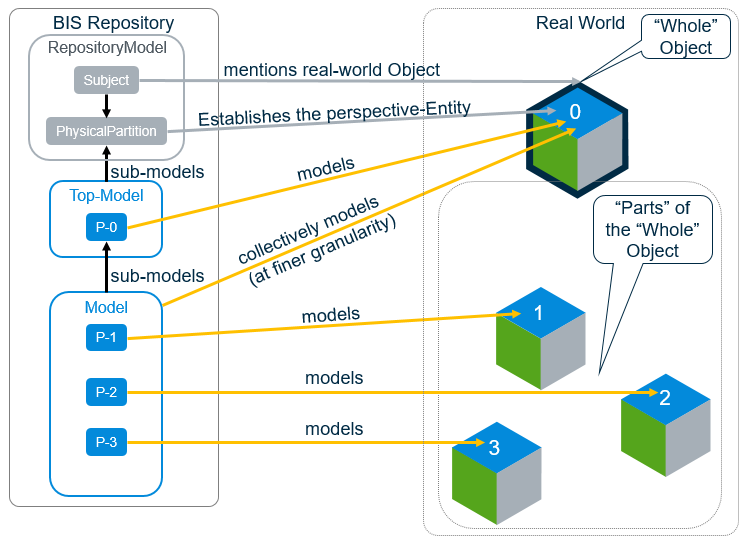
Contents of a top-Model
The top-Model models the complete Entity established by the Subject and partition.
The top-Model should contain one Element for each discrete Object included in the Subject. When the modeled Subject refers to a single discrete Object, the top-Model will contain only a single Element that corresponds directly to a perspective on that Object. In this case, the Code and DisplayLabel of that Element may be the same or similar to that of the Subject (particularly if this is the [Primary Perspective] for the Object.) because they are “about” the same thing.
When the modeled Subject is ‘compound’ (referring to multiple discrete Objects), there will be multiple Elements in the top-Model. An example compound-Subject might be “Deliverables of Phase II of Project X”. The project’s contract will contain a list of the top-level things-to-be-built, and the top-Model would contain one Element for each thing-to-be-built in that list. This honors the Single Responsible Party Principal (SRPP) because one General Contractor will ultimately be responsible for all of the deliverables.
If you find that a top-Model is unable to follow the SRPP, then the modeled-Subject needs to be decomposed into child Subjects. For example, with a compound-Subject like “The Dock and the largest boat that must be able to dock there”. The top-Model for that Subject would contain separate Elements for the dock and the boat, but a single party is unlikely to be responsible for both. Creating “Dock” and “Boat” child Subjects solves this problem.
Modeling from the “Top-Model” on down
The top-Model is where modeling from a given perspective really begins. As a domain author, you are faced with many options for modeling your domain, which are described below.
Multiple domain contexts
There will be distinct Digital Twins for design phases like Design, Construction, and Operations, and for major categories of infrastructure like Cities or Buildings or other facilities. There should be as much commonality among these as possible, but the domain author must have an awareness of the kinds of Digital Twins and the range of workflows where their domain is relevant. The modeling decisions discussed below occur in the context of those Digital Twins and workflows.
Domain authors should study examples of other domain schemas to see how others have addressed modeling challenges.
The many considerations
The domain author has a tough job. They must consider:
- Object boundaries: Consider the real-world and conceptually carve it up into Objects
- Entity boundaries: Carve those Objects up into Entities.
- Whole-part relationships: Consider the whole-part relationships among the Entities (and how to model them.)
- Other Relationships: Consider other relationships among Entities (and how to model them).
- Attributes: Consider the attributes of the Entities (and how to model them).
The “Object boundaries” consideration is business-as-usual for data modelers and will not be covered here.
The “Entity boundaries” consideration is covered in discussions of Modeling Perspectives.
The remaining considerations will be covered in the following sections.
Whole-Part Relationships
Each Entity will be modeled with an Element. Does the Entity have “parts” that are worth modeling individually in the given context? The answer to that question will lead to one of three choices:
- “Atomic” Element: There are no “parts” to model. Atomic Elements can still model significant internal structure using the GeometryStream, Properties, and ElementAspects.
- Parent-Child Modeling: The whole Entity is modeled as “parts” consisting of a parent Element and its child Elements. The “sum” of the parent and child Elements models the whole Entity. These Elements implement IParentElement. See Parent-Child Relationships.
- Sub-modeling: The “parts” are modeled in a sub-Model of this Element. The sub-modeled Element represents the whole Entity. The “sum” of all Elements in the sub-Model of the Element also represents the whole Entity, but at a finer granularity. These Elements implement ISubModeledElement.
In the picture below, Entity 0 is modeled with an ISubModeledElement, so Element P-0 represents the whole Entity 0, and its sub-Model also represents the whole Entity 0, at a different granularity. Entity 4 is modeled as an IParentElement, so Elements P-4, P-5, and P-6 collectively represent Entity 4 and its parts.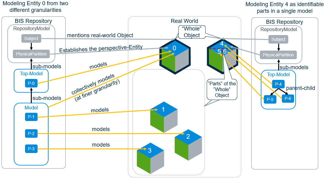
Use these questions to determine whether to use parent-child modeling vs sub-modeling: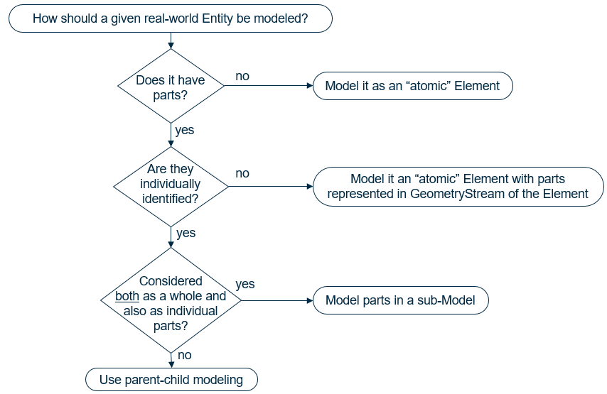
That last question needs elaboration. What are typical reasons why users need to both model the Entity as-a-whole and also model it as a collection of fine-grained parts? Reasons include:
- According to the SRPP, if one party determines that X should exist in a particular place, but delegates responsibility for modeling X in detail to a second party, the delegate would need to do their work in their own Model.
- If some workflows want to deal with the Entity-as-a-whole, but other workflows (e.g. fabrication for construction) need to deal with it as a set of parts, the fabricator would want a Model focused on the parts used to fabricate the whole.
As a boundary case, if one of the parts is clearly a “lead” part, e.g. a “Beam” with specific additions (welded on) or subtractions (cut out) then maybe parent-child is more appropriate. The decision to use parent-child modeling vs sub-modeling can be quite tricky. You should examine schemas from comparable domains and consult experts, if possible.
Modeling Systems
Physical infrastructure exists to implement one-or-more functions. A campus functions to provide learning to people. A building shelters people for work and play. A lock assembly helps provide security for a space. A landscape system may primarily function to provide pleasing aesthetics. Some functions are modeled explicitly (see Functional Models and Elements), but even if they are not modeled, the real-world functions are the reason that the physical infrastructure exists.
A “physical system” is a physical Entity (or a set of physical Entities) that implements a function. In this topic, “System” refers to a PhysicalElement that models a physical Entity that implements a function. Systems do not necessarily have “system” in their name, e.g. by this definition a “Facility” is a System implementing a high-level function and an “Assembly” is a System implementing a smaller function.
For a System that is sub-modeled, the sub-Model should only contain PhysicalElements that are part of that System and that are “owned” by the party responsible for the System, satisfying the SRPP. A System may be split into multiple Models for responsibility or other reasons. PhysicalElements that are part of more than one System reside in the Model of the System that “owns” them and can be “included” in other Systems using the PhysicalElementIncludesPhysicalElement relationship—allowing a single PhysicalElement to be shared by multiple Systems.
Systems tend to align with responsibilities
Organizing PhysicalModels by physical systems aligns with the SRPP, because responsibilities are typically assigned per system.
For example, the architect is responsible for the architectural Systems of the building. Those Systems partition and shelter spaces in useful ways. The architect will use one or more Systems with sub-Models containing the detailed walls, windows, and doors that make up a portion of an architectural System.
The structural engineer is responsible for structural members of the structural System that holds up the building. The structural engineer will use one or more Systems with sub-Models containing the beams, columns, and load-bearing walls that make up the structural System.
Since load-bearing walls (the responsibility of the structural engineer) are often part of the architecture System, the PhysicalElementIncludesPhysicalElement relationship can be used to “include” them in the architecture System.
In different contexts (like different lifecycle phases), responsibilities will change, and domain schemas should have enough flexibility to handle those cases. During design, the architect and structural engineer have legal responsibilities for the system they design. During operations, the architecture and structure are both the responsibility of the facilities manager. Theoretically the architectural and structural Models could be merged into one when transforming a Design Digital Twin into an Operations Digital Twin. In practice, that may be uncommon, because the segregation of the Models is not a real problem for the facilities manager, and keeping them segregated will make it easier to kick off a new renovation capital project. In any case, software should not be too “rigid” in its expectations of how Elements are organized into Models.
See Overlapping Systems for guidance on dealing with PhysicalElements that are part of two physical systems.
Overlapping Systems
During design workflows, multiple responsible parties may collaborate on the design of a single physical Entity. There are a wide variety of potential collaboration workflows involving the PhysicalElement modeling that physical Entity. We examine how BIS addresses this issue using the example of an architect and a structural engineer collaborating on the design of a load-bearing wall…
There are situations in which both the architect and structural engineer must be able to express differing “opinions” regarding the wall’s design. When using iModels, we intend to solve most of these cases via “branching” and a “pull-request” workflow—each party can make “suggested changes” to a given Element in their own branch and then make a “pull-request” for the other party to review, approve, pull, and merge the suggested changes.
There may still be cases where we need to temporarily allow the architect and the structural engineer to each have their own LoadBearingWall Element in their own Model, both modeling the same physical load-bearing wall Entity. The architect can use his/her Element to represent a “suggestion” to the structural engineer.
We must maintain clarity on which Element is the authoritative LoadBearingWall (in this case, the one in the structural Model). The authoritative LoadBearingWall may have a non-null FederationGUID and CodeValue, while the non-authoritative one should have NULL for those properties. There will also be a PhysicalElementIsANonAuthoritativeDuplicateOfPhysicalElement relationship to indicate which LoadBearingWall is a Non-Authoritative Duplicate (NAD) of the other.
When the collaboration is “done”, and both Elements are consistent, the non-authoritative LoadBearingWall should be deleted. The LoadBearingWall in the structural Model would be related to the architectural System via PhysicalElementIncludesPhysicalElement and related to a CompoundWall via AssemblyIncludesPhysicalElement. Any relationships that were pointing to the non-authoritative LoadBearingWall should be re-mapped to the authoritative one.
Consistency checks can ensure that all NADs are eliminated before designs are finalized and published for use in construction or operations, where redundant modeling of the same physical Entity creates problems.
3D Modeling Guidance
3D modeling is central to BIS and iModels. There is a hierarchy of 3D-related Modeling Perspectives.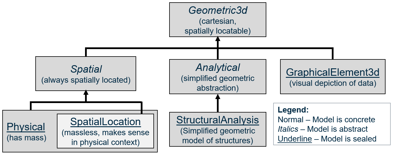
For each perspective, there are corresponding Model, and Element classes that have a similar inheritance hierarchy. There are corresponding InformationPartitionElement subclasses for some (but not all) of the perspectives.
“Spatial” is essentially a synonym for “uses real-world coordinates”. All of the perspectives inheriting from Geometric3d use a cartesian coordinate system that can be spatially located somewhere on the Earth. Specializations of SpatialModel are always in real-world coordinates. Other Specializations of GeometricModel3d can opt-out of being in real-world coordinates (and spatial indexed) by setting IsNotSpatiallyLocated=true.
The “Spatial” perspective is for modeling “real” stuff in “real” space, e.g. physical Entities and the spatial locations that they define or that define them. The non-Spatial perspectives are for mathematical abstractions or “pure graphics” that may or may not relate closely to physical Objects. The “Physical” perspective is for modeling physical Entities, which have mass and for modeling spatial location Entities. What is a “spatial location Entity”? It is massless, but manifests in the real physical world:
- They may be defined in relation to physical Entities, e.g. the air gap between two conductors, the space around an access panel, the volume occupied by a physical Entity, or an area indicating a region on the surface of a physical Entity.
- They may be used to guide positioning of physical Entities, e.g. gridlines that may be manifested physically on a construction site via chalk lines or laser beams.
- They may be abstractions of physical consequence, like property or political boundaries that are often demarcated in the physical world via markers, signs, or natural boundaries.
We define the “SpatialLocation” perspective as a strict subset of the “Physical” perspective, so that we can have SpatialLocationModels which do not contain any PhysicalElements. However, PhysicalModels can contain SpatialLocationElements. PhysicalModels and SpatialLocationModels can also contain GraphicalElement3d Elements (for annotations and illustrations of information) as well as non-geometric InformationContentElements.
The “Analytical” perspective is for modeling abstract mathematical/geometric Entities that are simplifications of the real world designed for a specific kind of analysis, such as a stick-figure model of complex structural steel beams and columns. Because every kind of analysis represents a unique perspective, the Analytical Partition, Model, and Element classes are abstract, and we expect analysis-specific concrete subclasses of them all.
3D Elements
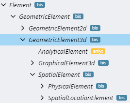
The Element class hierarchy mirrors the perspective hierarchy. Relationship constraints can use “SpatialElement” when they want a source or target Element to represent a “real” physical Entity or spatial location Entity.
3D Models
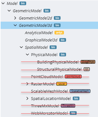
The Model class hierarchy also largely mirrors the perspective hierarchy, but it is complicated by legacy, deprecated classes, depicted with red strike-through, above.
There should be no specializations of bis:PhysicalModel, although a few specializations of bis:PhysicalModel were released before it was determined that bis:PhysicalModel should be “sealed”. We use validation rules to prevent additional specializations.
Any specialization of bis:PhysicalElement should be able to reside in any bis:PhysicalModel, though there is a plan to introduce a “Model Affinity” concept to allow a schema author to provide guidance on where they intend their Elements to be placed.
Use bis:SpatialLocationModel when sub-modeling specializations of bis:SpatialLocationElement, such as a “Grid” or “RealityLocationSet.
There are some other existing specializations of SpatialModel related to “reality modeling” which do not follow a pattern that we wish to promote or continue: PointCloudModel, RasterModel, ScalableMeshModel, ThreeMxModel, and WebMercatorModel. These sub-Model RepositoryLink Elements that point to external repositories of “reality data”. It was originally anticipated that they would contain SpatialLocationElements cached from the external sources, but this has not happened, in practice. They have JsonProperties that hold metadata about the data in the external repository.
3D Partitions
The bis:PhysicalPartition of a bis:Subject contains its “physical backbone”. There should not be more than one per bis:Subject.
The class bis:SpatialLocationPartition exists, but has not been used in practice and should be avoided. Since the “SpatialLocation” perspective is a subset of the “Physical” perspective, SpatialLocationElements can be part of the “physical backbone”.
We anticipate concrete specializations bis:AnalyticalPartition that will be analysis-specific.
Generally, the Partition and Model of a given perspective should have the same modifiers, e.g. they should both be either abstract, concrete, or sealed. If they are abstract, their corresponding Element class should be abstract. It is also common for the Partition/Model to be concrete or sealed while the corresponding Element is abstract, as is the case for Physical and SpatialLocation.
The class hierarchy under InformationPartitionElement is largely “flattened”. The 3D-related Partitions are highlighted below. As indicated, iModel authors should avoid usage of SpatialLocationPartition.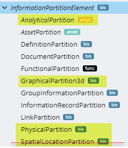
Guidance for new specializations of the 3D Geometric Perspective
If your new Element is modeling the physical geometry (including physical materials) of an Entity with mass, it should be a direct or indirect specialization of PhysicalElement. You will not create specializations of PhysicalPartition or PhysicalModel.
If your new Element is modeling a real-world location in space, then specialize SpatialLocationElement. Your element will either be placed in a PhysicalModel or a SpatialLocationModel that is sub-modeling some other SpatialLocationElement.
If your new Element is modeling a 3d geometric abstraction of something in real-world coordinates, you should specialize each of AnalyticalElement, AnalyticalModel, and AnalyticalPartition.
If your new Element doesn’t fall into any of the categories above, please consult with Bentley’s BIS experts to determine if new specializations of Geometric3d Partition/Model/Element are needed.
In all cases, new corresponding Model and Partition classes should have the same class qualifiers. Generally, both should be concrete or sealed.
Physical Models and Elements
Introduction
PhysicalModels and PhysicalElements are used to model the physical world, as it exists currently, as it existed in the past, or as it is expected to exist in the future.
Any object in the real world is modeled as a PhysicalElement a maximum of once within a BIS repository. The various disciplines that work together on infrastructure can not each have their own PhysicalElement for the same real-world object. Modeling the physical world is a cooperative, coordinated effort.
In BIS, the following classes are central in modeling the physical world:
- PhysicalElement
- PhysicalType
- PhysicalModel
PhysicalElements
PhysicalElements are use to model real world physical entities. PhysicalElements always have a position in real world coordinates that is relevant for infrastructure construction, operation or maintenance.
It is usually easy to determine which objects should be modeled by a PhysicalElement. If the answers to the following three questions are “yes”, then the object is a good candidate for modeling with a PhysicalElement:
- Does the object have mass?
- Can the object be touched?
- Are the spatial and location characteristics of the object important in constructing, operating or maintaining infrastructure?
For example, a paper contract has mass and can be touched, but its spatial and location characteristics are not important for infrastructure purposes, so it should not be modeled with a PhysicalElement.
Examples of entities that are modeled with PhysicalElements are:
- Pumps
- Roads
- Sewer Lines
- Cranes (when true shape and position is used in construction planning)
Examples of entities that are NOT modeled with PhysicalElements are:
- Property Lines
- Groundwater Elevations
- Construction Superintendents
- Cranes (when used only for resource planning)
See Element Fundamentals for more information on Elements.
PhysicalType
When many PhysicalElements are conceptually identical (such as pumps of the same model) except for a few details (such as location), PhysicalTypes are often used to provide simpler and more efficient modeling.
PhysicalTypes are often used when a particular PhysicalElement can be ordered from a catalog. PhysicalTypes can provide geometry and properties to the PhysicalElements to which they are related. Each PhysicalElement can be related to a maximum of one PhysicalType.
See Type Definitions.
PhysicalModels
Each PhysicalElement is contained in exactly one PhysicalModel. A PhysicalModel is a container of PhysicalElements (and potentially related Elements of other classes) that together model some real-world physical entity. For example, a PhysicalModel might model a campus, a building, a sewer system or a pipe rack.
See Model Fundamentals for more information on Models.
Physical Breakdown
Some PhysicalElements have associated “breakdown” PhysicalModels that model the same real world physical entity in finer granularity. For example, a SewerSystem PhysicalElement might be broken down into a SewerSystemModel that contains Pipe PhysicalElements that model the individual pipes in the sewer system.
See Element Fundamentals for more information on Model breakdown concepts.
Top of the World - PhysicalPartition
At the top of the PhysicalElement-PhysicalModel tree is a PhysicalPartition Element in the RepositoryModel. The PhysicalPartition Element is a child of a Subject Element and starts the modeling of that Subject from a physical perspective.
Aggregate PhysicalElements
As an alternate modeling technique PhysicalElement can have child Elements instead of breakdown Models. Elements with child Elements are essentially aggregates. For example, a SteelConnection might be an aggregate of Bolts, Plates and Welds.
See Element Fundamentals for more information on aggregates and child Elements.
Physical Backbone
As discussed in Modeling with BIS, there are many entities (physical, functional, analytical, etc.) for each real-world object that can be modeled in a BIS repository. There is a need to coordinate the Elements that model these entities. The strategy of BIS is to relate each of these Elements with the PhysicalElement that models the real world object. The hierarchy of PhysicalElements and PhysicalElements provides the “backbone” to which Elements representing the other modeling perspectives related.
Type Definitions
If we consider some primary Entity modeled by a primary Element. The Element’s ECEntityClass tells us what kind of Entity it is, and can add new ECProperties to for modeling the Entity. We can further classify instances into subsets where each subset has a shared set of property values. Each of these distinct sets of property values is a “type” of the primary Entity (characterized by having all of those property values in common). The properties are defined in a subclass of TypeDefinition, which defines the properties whose values are said to vary by “type”.
A TypeDefinition is similar to a IfcTypeObject.
Practically, these “types” tend to correspond to product-models (not to be confused with bis:Model) such as a Mazda model “RX-7” car. The product-model numbers typically identify entries in a catalog. The catalog entry will include other attributes whose values are shared by all instances of the product of the given product-model. A TypeDefinition represents such a catalog entry, with a Code being a product-model-number. Even if a primary Element is “custom” and does not actually come from a catalog, if can still have a custom “catalog entry”, e.g. an instance of TypeDefinition with custom values that are not in-common with other instances. It is essentially a “type” for which there is only one instance.
TypeDefinitions complement class inheritance. They differ from it in two important ways:
- TypeDefinitions are “instance data” in a BIS Repository. You can add new instances of TypeDefinitions without changing the BIS Domain Schema.
- TypeDefinitions contain values for ECProperties defined by their TypeDefinition ECEntityClass, but cannot introduce new ECProperties.
A primary Element instance will have a relationship (e.g. PhysicalElementHasType) to an instance of its type (e.g. a subclass of PhysicalType). The complete attributes of the Entity being modeled are found by combining the property values of the primary Element instance with the property values from its associated TypeDefinition instance.
If the primary Element instance has an ECProperty with the same name as one in its TypeDefinition, the instance-specific value overrides the type-specific value. This is similar to how IFC works with Property Sets applied to an instance or to the type.
For example, let’s say that we are modeling a double-hung window using ECEntityClass DoubleHungWindow. Most double-hung windows are ordered from a catalog, and the only permutations of height and width of window that you can get are those that are listed in the catalog. The author of the DoubleHungWindow ECEntityClass with also define a subclass of TypeDefinition (or its subclass PhysicalType) DoubleHungWindowType that has ECProperties for all properties of double-hung windows that vary per-type (per catalog-entry) rather than per instance, e.g. Height, Width and IsInsulated. For many products, not much other than the spatial placement of the entity will vary per instance. For our double-hung window, there might be 4 types, where each has a CodeValue that is its product-model-number: 2x4I, 2x3I, 2x4U, 2x3U. In a GUI, the list of TypeDefinition instances that are applicable to a given primary Element ECEntityClass can be used to populate a drop-down list of available “types” for the given ECEntityClass. The list of available types can be narrowed-down by defining specializations of the GeometricElement3dHasTypeDefinition Relationship.
This diagram shows both the class hierarchy for a PhysicalElement modeling a centrifugal pump along with an associated PhysicalType and a specialized relationship to relate them: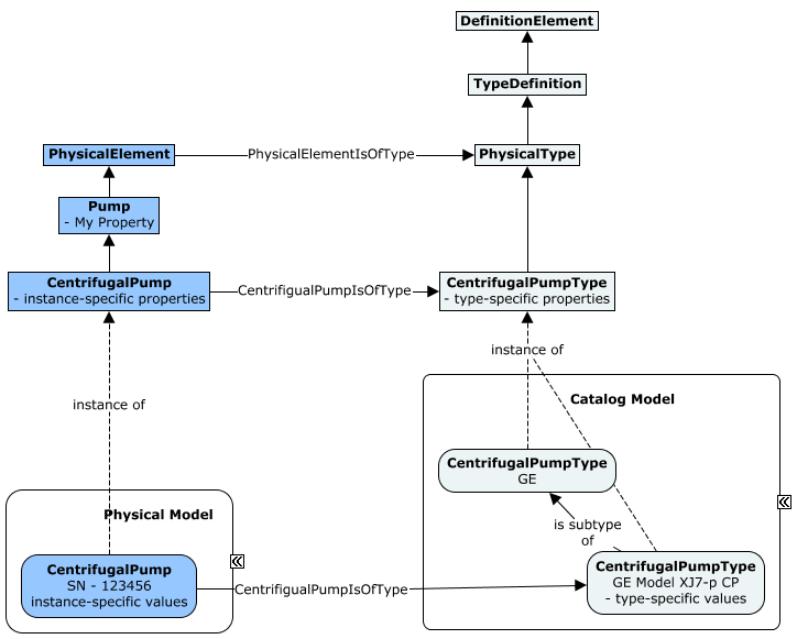
Though we describe types here in terms of PhysicalElements, this pattern can be applied to other kinds of Elements. The relationships GeometricElement2dHasTypeDefinition and GeometricElement3dHasTypeDefinition make the pattern usable for geometric elements, but new relationships classes could be added to support a “type-system” for other kinds of Elements.
Functional Models and Elements
Introduction
The functional domain allows defining objects that represent systems or processes. These objects define the requirements of the objects in a system. For example, a Functional Pump has attributes that define the required fluid flow for a process.
The functional definition of a process is usually defined early in the design of a project. These objects show up in design diagrams and data sheets. The Functional objects eventually will be created in the Physical model. The physical objects will be related to the functional object with a fulfills relationship.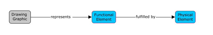
Functional Elements
All the Functional classes are defined in the Functional schema (which has an alias of func). There are two classes of functional elements, func:FunctionalBreakdownElement and func:FunctionalComponentElement. Each of these class inherit from the abstract class func.FunctionalElement.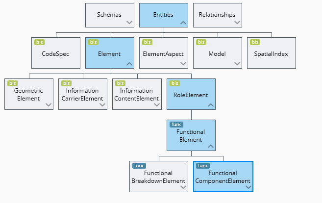
FunctionalBreakdownElements are used to defined breakdown structures in a functional model. These elements group other FunctionalBreakdownElements or FunctionComponentElements. For example, a Plant Unit would groups Plant Sub-Units. A Plant Sub-Unit groups Equipment and Pipeline. Or a BuildingRequirement groups BuildingStoryRequirements. BuildingStoryRequirements groups SpaceRequirements.
FunctionalComponent elements are use to represent the individual engineering requirement objects. For example, Pumps, Valves. These classes contain attributes that define the engineering requirements for the component.
FunctionalModels
The func:FunctionalModel class is defined in the functional domain schema. FunctionalModels contain the FunctionalElements needed to define a system or process. It would be common to have more then one FunctionalModel, but each would be related to a different process or system.
Currently, Plant and Building create functional models. There has not been a need to sub-class the Functional model because both applications puts all their function object into one model.
Contents of Functional Models
FunctionalModels contain both FunctionBreakdownElements and FunctionalComponentElements. These models will contain all the elements needed to describe a system or process. For example, a building application would typically create one FunctionalModel per building.
Functional Models in Model Hierarchy
In most cases today, the functional model models a partition related to the root subject.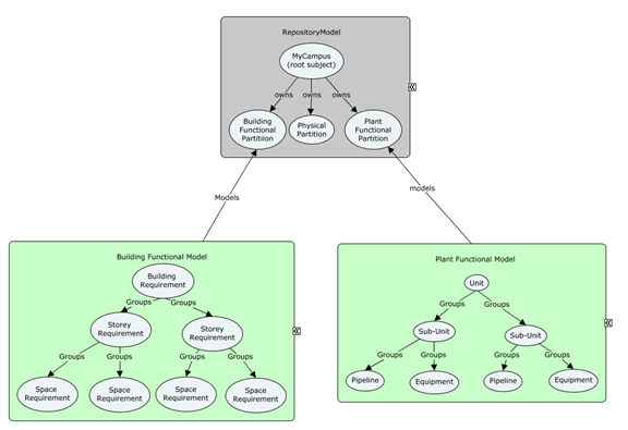
Example
In the Plant functional domain there is a complete set of classes that define the functional requirements for the processes in a plant. There are Equipment, Piping and Instrument functional component class. There are functional breakdown classes. These classes can vary per project type. Power plant projects have Units, Sub-Units, Building and Systems. A refinery project has Units, Areas, Services and Systems. The plant applications allow user to define these functional breakdown class to suit their needs. This hierarchy is defined by the groups relationship. The order of the tree is defined in presentation rules. Functional Components maybe grouped in more then one Functional Breakdown hierarchy. For example, a pump could exist in the S1 sub-unit and the NSSS plant System.
Plant does have functional breakdown for pipelines and instrument loops that group functional components and are always the end of the function breakdown hierarchy. They are only configurable by adding properties. There are many non-configurable relations that relate functional components to one another to define the layout of the function model. **See diagram.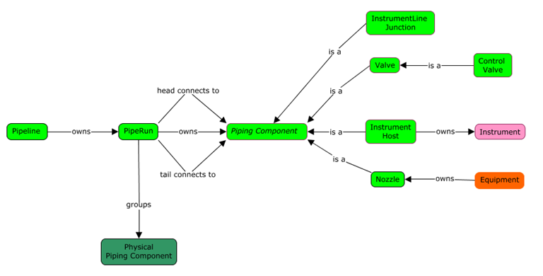
Analytical Models and Elements
Introduction
AnalyticalModels are models used to facilitate analyses of infrastructure. Analyses that require an AnalyticalModel typically are specialized analytical perspectives that cannot be performed directly on PhysicalModels as the physical world is too complex; these analyses require simplified geometry and other data. AnalyticalModels are similar in purpose to FunctionalModels, but have one significant difference: they are models in true world coordinates.
Typically each AnalyticalModel is relevant to only one type of analysis. A particular PhysicalModel (e.g. a building) may have multiple associated AnalyticalModels. Examples of the analyses facilitated by AnalyticalModels are Hydraulic analysis, Building energy analysis, Traffic analysis and Structural analysis.
Analytical Elements
AnalyticalElements are simplified representations of real physical infrastructure. An example of an AnalyticalElement is a Pipe Segment (not a physical pipe) in a Hydraulic Analytical Model. This Pipe Segment might have a simple 2D line segment location, together with a set of hydraulic analytical properties; it would also likely have relationships to other Hydraulic Analytical Elements in the network being analyzed.
AnalyticalElements must always be contained in AnalyticalModels. AnalyticalElements will frequently have AnalyticalElementSimulatesSpatialElement relationships to the PhysicalElements or SpatialLocationElements that model the same real world infrastructure. This relationship, however, is not always 1:1.
Analytical Models
AnalyticalModels exist to facilitate the analyses of infrastructure. AnalyticalModels contain – directly or indirectly - all of the information necessary for one or more analysis of single type. For some Analytical domains, it may be appropriate to have more than one AnalysisModel for a PhysicalModel.
Contents of Analytical Models
AnalyticalModels contain AnalyticalElements, but they may also contain other types of Elements. AnalyticalModels will frequently contain InformationElements. AnalyticalModels never contain PhysicalElements.
Analytical Models in Model Hierarchy
As AnalyticalModels are used to assist in the design or understanding of physical infrastructure, AnalyticalModels are often linked to PhysicalModels. Such link is expressed via AnalyticalElementSimulatesSpatialElement relationships between their elements.
At the Top of the World, a specialized analysis is introduced via an AnalyticalPartition subclass, which is broken down by an AnalyticalModel.
Typical Analytical Model Workflows
AnalyticalModels are expected to be used in three basic scenarios:
- AnalyticalModel is derived from a PhysicalModel
- PhysicalModel is derived from an AnalyticalModel
- AnalyticalModel is used without relationship to a PhysicalModel.
Deriving an AnalyticalModel from a PhysicalModel is expected to be a common workflow. Existing or planned infrastructure will frequently be modeled and need to be analyzed. The derivation of the AnalyticalModel may be automated, partially automated or manual. The derivation will typically create AnalyticalElementSimulatesSpatialElement relationships between the AnalyticalElements and the PhysicalElements or SpatialLocationElements. These relationships can be used later to assist with updating the AnalyticalModel when the PhysicalModel changes, or in creating a two-way syncing of information between the two models.
Deriving a PhysicalModel from an AnalyticalModel may be a common workflow for new infrastructure when the analytical design of the infrastructure occurs before the physical design. The derivation of the PhysicalModel from the AnalyticalModel is often a simple automated operation, but typically does not produces a fully-detailed PhysicalModel. As with the Physical-to-Analytical derivation, AnalyticalElementSimulatesSpatialElement relationships will typically be created. These relationships can be used for updating and two-way syncing.
A standalone AnalyticalModel that is not related to a PhysicalModel is a valid configuration. This configuration might be used when the organization using the iModel is only involved in the analytical investigation.
Example - Building Thermal Analysis
Building thermal analysis is one likely use of AnalyticalModel. This specialized analysis is introduced in the model hierarchy via a subclass of AnalyticalPartition.
The exterior envelope and interior partitions of the building might be modelled with an EnvelopePanel subclass of AnalyticalElement which would contain information on the panel shape, with relevant infrared radiation transmittance, thermal mass and thermal insulation properties. These EnvelopePanel elements would be related back to whatever items in the PhysicalModel that they were representing.
Similarly, AnalyticalElement subclasses would be created to represent the key components of the HVAC system. These would also be related back to their associated PhysicalElements.
InformationElement subclasses would be used to record other parameters for the analysis, such as weather scenarios and building operating assumptions.
The complete results of the thermal analysis would likely be large and would not be stored directly in the iModel. However, key or summary results would likely be stored in Elements (InformationElements or AnalyticalElements) in the AnalyticalModel.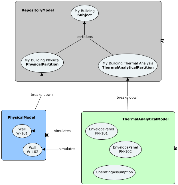
Information Models and Elements
Introduction
A BIS repository contains elements of many types. PhysicalElements are used for modeling physical objects in the real world. RoleElements are used for modeling roles or functions that an object could have. InformationContentElements are used for modeling pure information. BIS defines a set of InformationContentElement subclasses to further classify and specialize behavior for different types of information.
Key Information Element Classes
InformationContentElement
InformationContentElement is an abstract base class for modeling pure information entities Only the core framework should directly subclass from InformationContentElement. Domain and application developers should start with the most appropriate subclass of InformationContentElement.
InformationRecordElement
InformationRecordElement is an abstract base class for modeling information records. InformationRecordElement is the default choice if no other subclass of InformationContentElement makes sense. For example, importing a spreadsheet may cause InformationRecordElements to be created.
An InformationRecordElement is typically contained by an InformationRecordModel.
DefinitionElement
A DefinitionElement holds configuration-related information that is meant to be shared.
DefinitionElement subclasses include:
- Category
- SubCategory
- RenderMaterial
- PhysicalMaterial
- AnnotationTextStyle
- LineStyle
- Texture
- ModelSelector
- CategorySelector
- DisplayStyle
- ViewDefinition
- GeometryPart
A DefinitionElement is always contained by a DefinitionModel. A DefinitionModel can be used to collect together related definitions.
Example usages:
- A DefinitionModel per “catalog” where each DefinitionModel is correlated to a catalog and contains a DefinitionElement per catalog entry.
- A user could create a DefinitionModel to collect together project standards (styles, categories, etc.)
A developer could create a private DefinitionModel to hold application or domain definitions and configuration settings.
InformationPartitionElement
InformationPartitionElement is an abstract base class for elements that indicate that there is a new modeling perspective within the overall repository information hierarchy. An InformationPartitionElement is always parented to a Subject and broken down by a Model. An InformationPartitionElement is always contained by the RepositoryModel.
See Information Hierarchy for more details.InformationReferenceElement
InformationReferenceElement is an abstract base class for modeling entities whose main purpose is to reference something else. For example, any sort of hyperlink or grouping type of information.
InformationReferenceElement subclasses include:GroupInformationElement
- LinkElement
-
GroupInformationElement
GroupInformationElement is an abstract base class for modeling entities whose main purpose is to reference a group of related elements. For example, a DgnV8 named group is mapped onto a subclass of GroupInformationElement.
LinkElement
LinkElement is an abstract base class for modeling hyperlinks.
LinkElement base classes include: UrlLink
- RepositoryLink
-
Subject
Subjects are Elements that are used to identify things that the repository is about. Subjects are logical references to those external things.
See Information Hierarchy for more details.Document
A Document is a collection of information that is intended to be understood together as a whole.
Document subclasses include: Drawing
- Sheet
Typical Models for Specific Information Elements
The following tables lists the Model types that typically contains specific subclasses of InformationContentElements:
| Element Class | Model Class |
|---|---|
| InformationRecordElement | InformationRecordModel |
| DefinitionElement | DefinitionModel |
| InformationPartitionElement | RepositoryModel |
| InformationReferenceElement | LinkModel or other InformationModel |
| GroupInformationElement | GroupInformationModel |
| Document | DocumentListModel |
PhysicalModel Hierarchy
Introduction
Each Subject in a BIS Repository can have one PhysicalPartition child Element, under which the PhysicalModels pertaining to the Subject will be organized using mechanisms described in Model Hierarchy. The Model Hierarchy is constrained by Modeling Perspective, but within the Physical Perspective, it is desirable to further organize Models according to Sites, Facilities, Systems, and Components to make the hierarchy of Models understandable by software and users. This section describes “Model Affinity” (a way of specifying “constraints” on the ModelContainsElements relationship) and the best-practice for using them to organize the Physical Model Hierarchy.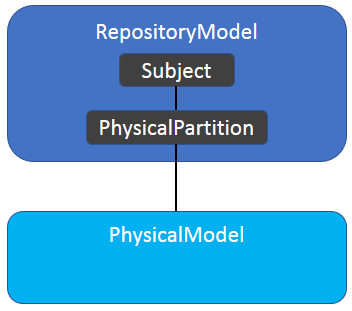
Organization Strategy
Motivations
BIS defines a data model that is shared by a growing set of applications and services. Many of these applications and services read and/or write PhysicalModel data. There are two choices to ensure that these applications and services will be coordinated:
- Require every application and service to work with any data organization.
Specify a data organization which applications and services should read and write.The second option has been chosen for BIS as it is the more practical solution.The strategy and organization described in this page may seem overly complex to domain developers who just want to model a widget network. These developers naturally want a simple organization that has a network of widgets in the top-most PhysicalModel. The problem with this widget-centric data organization is that there will be users who want to model widget networks, thingamajig systems and doohickey facilities and coordinate between them; how can these users do that if the top model is dedicated to widgets?BIS has been created to facilitate multi-discipline coordination, and that naturally adds some complexity to single-discipline use cases.
Predictability vs Flexibility / Strong vs Weak Type Safety
A choice must be made between strong type-safety and weak type-safety.
Strong type-safety (e.g. RetainingWall can only be contained in a StructuralSystem Model), provides strict checking to ensure that type-related rules are always followed, and hence results in very predictable models that software can easily process. However, strong type-safety limits flexibility and can cause frustration (e.g. I have to create a StructuralSystem Model just to create a single RetainingWall?). Another concern with strong type-safety is that real-project experience with BIS is very limited, so the schema designers understanding of real-world workflows with BIS data is limited; there is a risk of schema designers making strong type-safety decisions that are proved over time to be incorrect.
Therefore, Weak type-safety has been selected for the PhysicalModel hierarchy organization.
Validation rules will be created to determine if PhysicalElements reside in appropriate Models and the PhysicalModel hierarchy is appropriate, but there will be no prohibitions that ensure that the PhysicalModel hierarchy meets certain standards.
This page provides an overview of the basis of those validation rules and the mechanisms for defining them.PhysicalModels and the Elements that they Model
As described in Model Hierarchy, every Model breaks-down an Element. The Model and the Element represent the same real-world Entity, but the Model provides more granular information about the Entity.
Breakdown Models are weakly-typed in BIS. To understand the real-world Entity that a Model is modeling, it is necessary to look at the Element which the Model is breaking down. PhysicalModel should not be subclassed. The few PhysicalModel subclasses that exist are deprecated and should not be used. When terms such as “Site Model” are used, they indicate “a Model that breaks down a Site”, but do not indicate a strongly-typed SiteModel.
ModelAffinity Custom Attribute
While strong-typing is not used, there is still a desire to provide validation of the organization of the data in a PhysicalModel hierarchy. To run this validation, the software must be able to determine which Models are appropriate containers for each Element. This is determined through the ModelAffinity custom attribute.
The ModelAffinity custom attribute can be applied to any PhysicalElement subclass. It declares for the class:Which Elements’ breakdown Models this Element has an affinity for (multiple can be declared).
- The strength of that affinity.
- The rationale for the affinity.
There are three levels of affinity strength:
- Required - not residing in an appropriate Model should trigger a validation error.
- Recommended - not residing in an appropriate Model should trigger a validation warning.
- Suggested - not residing in an appropriate Model should trigger a validation note.
In the future, ModelAffinity information may be used to provided improved UI tools.
Example Usage
Here is an example of the ModelAffinity custom attribute in use:
Inherited ModelAffinity
ModelAffinity cannot be overridden in subclasses, but it can be narrowed. The effective affinity setting for a class is the sum of all the defined ModelAffinity attributes in the class and all of its superclasses.
For example, if:
- There is a Pipe class with a SewerPipe subclass.
- Pipe has an affinity to ISystem.
- SewerPipe has an affinity to SewerSystem
Then the validation for SewerPipe would confirm:
- SewerPipe instances reside in ISystem Models.
- SewerPipe instances reside in SewerSystem Models.
A SewerPipe placed in a Site Model would generate two warnings (or errors) during validation; one for not being in an ISystem Model and one for not being in a SewerSystem Model.
When an ancestor class has already defined a ModelAffinity, it only makes sense to define a narrowing ModelAffinity in a subclass. Defining a conflicting ModelAffinity is a symptom of the design of the subclass conflicting with the design of the superclass.
Syntax Details
TODO: Remove this section after discussion and implementation
This custom attribute is written so it could be applied to other Elements (not just PhysicalElements) in the future.
Mixin Classes
ModelAffinity custom attribute instances can refer to mixin classes, but cannot be applied to mixin classes.
The mixin classes ISite, IFacility and ISystem are used in the ModelAffinity custom attribute for many key PhysicalModel hierarchy classes.
Top PhysicalModel
The top PhysicalModel (the one directly owned by the PhysicalPartition) should contain a single PhysicalElement that corresponds to the Subject (that owns the PhysicalPartition). As Subjects define their subject in text only, the subject may be vague (Is “Burj Khalifa” only the building, or is it the building and the surrounding site?”). This vagueness is clarified by the PhysicalElement that is in the top PhysicalModel.
The top PhysicalModel most often contains an ISite, IFacility, or ISystem PhysicalElement.
Top PhysicalModels with More than One PhysicalElement
There is no strict requirement limiting the top PhysicalModel to contain only a single PhysicalElement. iModels that are generated from other repositories will sometimes have top PhysicalModels with multiple PhysicalElements as that best matches the organization of the source data. Legacy data may also have a non-standard organization.
PhysicalModel Hierarchy Strategy
While ModelAffinity provides a mechanism to declare and enforce a PhysicalModel hierarchy, it does not define a coordinated strategy. The strategy for organizing the hierarchy relies on classifying PhysicalElements into five types:
- Site - An area of land and its contents.
- Facility - A cross-disciplinary Entity such as a building, bridge, tunnel, wharf, etc.
- System - A single discipline physical system, such as structural system, electrical system, sewer system, etc.
- System Component - A component for a particular system.
- General-Use Component - A component that does not have any ModelAffinity.
The overall PhysicalModel hierarchy strategy is defined in the following table:
| Classification | Affinity to | Example Classes |
|---|---|---|
| ISite | ISite (declared in implementing classes) | Site |
| IFacility | ISite, IFacility, ISystem (declared in implementing classes) | Building, Bridge, Tunnel |
| ISystem | ISite, IFacility, ISystem (declared in implementing classes) | SewerSystem, StructuralSystem, etc. |
| *System | ISite, IFacility, ISystem | SewerSystem, StructuralSystem |
| *SystemComponent | *System | SewerPipe, Beam |
| General-Use Component | (none) | Bolt, Chair |
These types and their behaviors are explained below, along with the behaviors of their breakdown PhysicalModels if they have breakdown Models.
ISite
ISite is mixin class that represents an region of land and all that is contained on, above and below that land. The ISite mixin applies only to PhysicalElement classes.
In conversation (and writing) the Models that break down Site Elements are referred to as Site Models, even thought there is not a strongly-typed SiteModel class. By convention, the top-most Model in a PhysicalModel hierarchy is considered a Site Model, even though it breaks down PhysicalPartition.
ISite Models typically contain ISite, IFacility, ISystem and General-Use PhysicalElements.
ISite Elements should only be placed in ISite Models (and the top PhysicalModel). ISite Elements placed in any other Model will generate validation warnings.
To implement this behavior every class that includes the ISite mixin must include a ModelAffinity custom attribute that indicates a “Recommended” affinity to PhysicalPartition and ISite.
IFacility
IFacility is a mixin class that represents a significant multi-disciplinary infrastructure Entity that corresponds well to user concepts. Buildings, bridges, tunnels, wharves, and towers are all examples of multi-discipline Entities that are modeled with a PhysicalElement subclass that includes the IFacility mixin.
In conversation (and writing) the Models that break down IFacility Elements are referred to as Facility Models, even thought there is not a strongly-typed IFacilityModel class. These Models are usually referred to by their more-specific Element types (e.g. Building Models are Models that break down Building Elements.)
IFacility Models typically contain IFacility, ISystem and General-Use PhysicalElements.
IFacility Elements may be placed in ISite, IFacility and ISystem Models. IFacility Elements placed in any other Model will generate validation warnings.
To implement this behavior every class that includes the IFacility mixin must include a ModelAffinity custom attribute that indicates a “Recommended” affinity to PhysicalPartition, ISite, IFacility and ISystem.
ISystem
ISystem is a mixin class that represents a significant discipline-specific arrangement of Entities intended to fulfill one or more functions. Sewers, roadways, HVAC and fire-suppression systems are all examples of real-world Entities that are modeled with ISystem subclasses. ISystem subclasses tend to be suffixed with ‘System’ (e.g. StructuralSystem, SewerSystem); ‘Network’ is another commonly used suffix for these classes (e.g. RoadNetwork).
Architecture is also considered an ISystem, as it is discipline-specific and has the same general behaviors at the other ISystems.
In conversation (and writing) the Models that break down ISystem Elements are referred to as System Models, even thought there is not a strongly-typed ISystemModel class. These Models are usually referred to by their more-specific Element types (e.g. SewerSystem Models are Models that break down SewerSystem PhysicalElements.)
ISystem Models may contain IFacility, ISystem and General-Use PhysicalElements, as well as components specific to the particular ISystem (e.g. SewerPipe in SewerSystem)
ISystem Elements may be placed in ISite, IFacility and ISystem Models. ISystem Elements placed in any other Model will generate validation warnings.
To implement this behavior every class that includes the ISystem mixin must include a ModelAffinity custom attribute that indicates a “Recommended” affinity to PhysicalPartition, ISite, IFacility and ISystem.
System Components
System Component represents an Entity that is part of a specific ISystem and generally does not makes sense outside of the specific system (e.g. sewer pipe outside of sewer system). System Component is not a BIS class, nor mixin.
System Components are identified by their ModelAffinity with a specific ISystem subclass.
System Components rarely have breakdown Models.
System Component Elements should only be placed in their related System Models. System Component Elements placed in any other Model will generate validation warnings.
To implement this behavior every System Component class must define or inherit a ModelAffinity custom attribute that indicates a “Recommended” (or stronger) affinity to the particular ISystem class that is appropriate for the System Component.
General-Use Components
General-Use Components represents Entities such as bolts and chairs which are not specific to any discipline or facility.
General-Use Components are identified by their lack of any ModelAffinity.
General-Use Components rarely have breakdown Models.
General-Use Elements can be placed in any PhysicalModel. General-Use Components never generate validation warnings.
Example
The following diagram illustrates all variations of the PhysicalModel hierarchy breakdown that will not generate warnings or errors.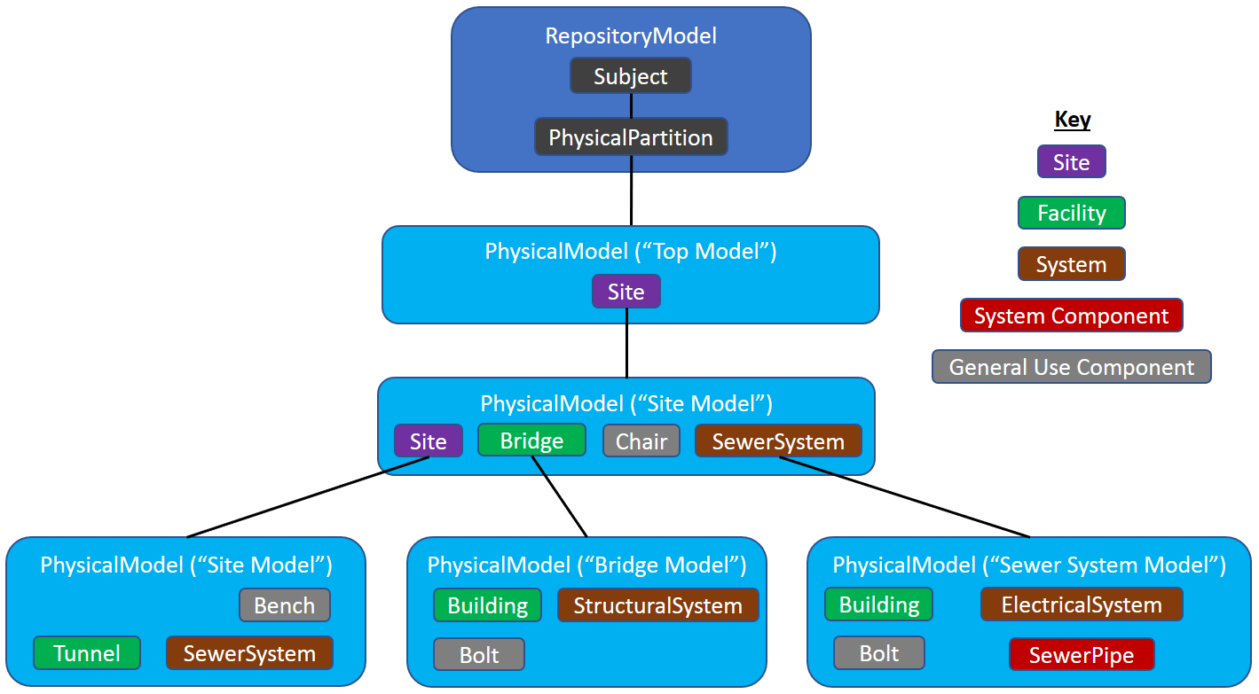
Discussion
This section is for discussion of both the content of the documentation and the BIS strategies and policies that back that content.
Changes Since June 22 2018
Site has been changed to ISite. Resulting in moderated changes (including one image change).
The top PhysicalModel has been given its own behavior, recommended use and clarified relationship to its Subject.
Site Class
We need a Site class that implements ISite. Should it be Sealed?
Implementation Tasks
- Create ModelAffinity Custom Attribute
- Create schema that defines ISite, IFacility and ISystem.
- Create Site class
- Provide validation of ModelAffinity usage?
- Provide validation code/capability that uses ModelAffinity data.
Categories
A Category is a property of a GeometricElement that categorizes its geometry. That is, every GeometricElement is in one and only one Category.
The visibility (on/off) of a category may be controlled per-view.
Categories are similar to levels in DGN, layers in DWG, and categories in RVT.
Category Classes
There are three Category classes, with this hierarchy:
- DefinitionElement
- Category (abstract)
- DrawingCategory (concrete & sealed)
- SpatialCategory (concrete & sealed)
- Category (abstract)
DrawingCategory is used for classifying GeometricElement2d elements via the GeometricElement2dIsInCategory (concrete & sealed) relationship. GeometricElement2dIsInCategory relates each GeometricElement2d with exactly 1 DrawingCategory.
SpatialCategory is used for classifying GeometricElement3d elements via the GeometricElement3dIsInCategory (concrete & sealed) relationship. GeometricElement3dIsInCategory relates each GeometricElement3d with exactly 1 SpatialCategory.
Note that Categories are not relevant for Elements that are not subclasses of GeometricElements.
SubCategories
A SubCategory is a subdivision of a Category. SubCategories allow GeometricElements to have multiple pieces of Geometry that can be independently visible and styled (color, linesStyle, transparency, etc.)
It is important to understand that a SubCategory is not a Category (i.e. Categories do not nest.) GeometricElements are always related to a Category, not a SubCategory. That is, it makes no sense to say a GeometricElement is “on” a SubCategory.
A SubCategory always subdivides a single Category. This relationship is defined by the CategoryOwnsSubCategories relationship. Every Category has one SubCategory called the default SubCategory.
An example of a Category is “Window”. The “Window” Category might contain SubCategories “Pane”, “Mullion” and “Hardware”. If the Window Category is displayed, the Pane SubCategory may be displayed while the Mullion SubCategory may be turned off.
Note: If a GeometricElement’s Category is off, the element is not displayed, period. SubCategory is only relevant when the Category of the element is displayed.
Category Rank
Categories have a property called Rank that is defined by this enum:
enum class Rank{System = 0, //!< This category is predefined by the systemDomain = 1, //!< This category is defined by a domain.Application = 2, //!< This category is defined by an application.User = 3, //!< This category is defined by a user.};
Category and SubCategory CodeValue
Category and SubCategory names comes from their CodeValue.
To avoid creating names that are unprintable, indistinguishable to users, and/or cannot be export to other systems, the following characters are disallowed in Category and SubCategory names:
<>\/.\”?*|,=’&\n\t
Category CodeScope
Category is a subclass of DefinitionElement, and are therefore required to be in DefinitionModels. By convention, the Codes for Categories are scoped to their DefinitionModel.
For Categories that are meant to be specific to a discipline or Domain, create a DefinitionModel and use it for your Categories. This permits each Domain to have a unique set of Categories, even though their names are not necessarily unique across the Domains.
SubCategory CodeScope
The CodeScope of a SubCategory is always its parent Category. That is, SubCategory CodeValues are only unique within their Category.
SubCategory References in GeometryStreams
Every GeometricElement2d and GeometricElement3d has a Category. They also have a GeometryStream property that defines the geometry of the Element. Within that GeometryStream, 0..N references can be made to SubCategoryIds of the element’s Category to control the visibility and style of entries within the GeometryStream. Any reference to a SubCategoryId that is not a SubCategory of the element’s Category is rejected.
Domain Standardization of SpatialCategories
Every Domain should provide standard Categories for the GeometricElements that it creates. Categories will often correspond to classes in the Domain (“Door”, “Window”, “Beam”, etc.). SubCategories within each Category may correspond to portions of the GeometricElement (“Hardware”) or to important geometric aspects of the GeometricElement (“CenterLine”).
Every SpatialElement subclass does not need its own SpatialCategory. Two common SpatialCategory patterns are:
- A SpatialCategory is used for a class and all its descendent classes.
- A SpatialCategory is used for a set of unrelated classes that have some conceptual similarity but do not fit rule 1.
User Control of DrawingCategories
DrawingCategories are similar to drawing layer/level standards and are ultimately under the control of the user. It is intended that DrawingCategories will be distributed via catalogs in the future.iModel Connectors and Categories
Each iModel Connector job should create a DefinitionModel for its Categories. That way each connector can have its own set of Categories without risk of name collision with other jobs.
iModel Connectors should respect and use the standard SpatialCategories defined by the Domains.
Schema Customization
Introduction
While BIS models a significant portion of the world of built infrastructure, and new discipline-specific domain schemas are being added all the time, there will inevitably be a need to store data not-yet-covered by BIS. Some common cases where this situation may arise are:
- Customizations and extensions to existing BIS concepts (often per-project or per-company)
- Vendor-specific information
- Transfer of information from other infrastructure-related databases (e.g. via iModel connectors).
- Modeling of concepts that do not currently exist in BIS.
- The need to add unstructured information to Elements.
This page discusses strategies available for creating and controlling this data, referred to as “custom data”, and provides best practice advice. Custom data should be modeled differently depending on the nature of the data and how the property definitions and values vary.
Properties that vary per class or type should be modeled using property definitions, properties which vary per instance should be modeled using Json.
Vendor Data and Related Catalogs
Vendors will often need to define Element subclasses and associated Type subclasses. For example a pump vendor might define a Pump subclass (BigCo:MonsterPump) and a related PumpType subclass (BigCo:MonsterPumpType).
BigCo:MonsterPumpType might define four new properties:
- ModelNumber
- Power
- InletDiameter
- OutletDiameterBigCo:MonsterPump might define one new property:
- OutletLength
When BigCo’s pump catalog is distributed, it will include:
- BigCo:MonsterPump class definition
- BigCo:MonsterPumpType class definition
Multiple BigCo:MonsterPumpType instances (defining the pump types available for purchase)
Data Imported from Other Databases (including via iModel Connectors)
The technology (often iModel connectors) that converts data from other databases into BIS data will usually need to convert from the class structure in the native database to a BIS class structure. It is rare that a BIS schema will work “out of the box”. Typically a dynamic schema will need to be defined by the converter and then the data converted from the native DB into instance of the new dynamic schema’s classes (likely along with some instances of standard BIS classes).
Dynamic Schema Minor Change Considerations
As dynamic schemas are extensions of BIS schemas, they must follow the rules of BIS schemas to prevent upgrade problems. These rules are defined in Schema Versioning and Generations. The most notable of these rules is that classes and properties cannot be removed or significantly redefined. In general, only additions to schemas are allowed.
Minor (BIS) Schema Upgrade Considerations
As defined in Schema Versioning and Generations, BIS schemas may be upgraded at almost any time within a generation. The classes in dynamic schemas always subclass from BIS classes, so they may be affected by these minor upgrades at almost anytime.
The biggest danger from these minor schema upgrades is that a BIS class may add a property that has the same name as a property in a dynamic subclass. This class will cause ????????????? when the upgraded schema is imported into a BIS repository.
Class name conflicts (a class being added in BIS that has the same name as a class in a dynamic schema) is not a technical problem as the classes are scoped by the name of the schema that contains them. The duplicate class names can cause user confusion, however.Generational (BIS) Schema Upgrade Considerations
As defined in Schema Versioning and Generations, generational changes allow radical changes to schemas and must be accompanied by code that understands how to map data (Elements and Models) from one generation of schemas to another. The generational mapping code can potentially be very complex; for example, it may include:
1:1, 1:N, N:1, N:N instance mapping
- 1:1, 1:N, N:1, N:N property mapping
- Moving of properties between classes (as a simple case, from PhysicalElementType subclass to its related PhysicalElement subclass)
- Rearrangement of Model hierarchy
Data Evolution Across Time
Introduction
BIS needs to support modeling of infrastructure that evolves over time. The evolution may be as simple as defining a few new properties to elaborately detailing an item. BIS supports this entire range.
For this appendix, a staircase will be used as an example to illustrate evolution over time. The designer of the Stair class will not be able to predict all possible information that may need to be associated with the stair in the future, or how complex a Stair definition will be needed.
Start Simple
It is best to start with as few assumptions and requirements as possible. The Stair class designer determines that Stair is a PhysicalElement, and gives it a definition such as “A vertical passageway allowing occupants to walk (step) from one floor level to another floor level at a different elevation. It may include a landing as an intermediate floor slab.” (which was copied from IAI). The Stair class needs no other complexity to be functional.
Simple Stair Inheritance Diagram
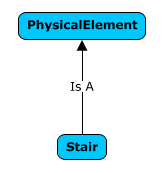
Simple Stair Instance Diagram

The Stair instance can be defined purely by the GeometryStream EC Property (inherited from GeometricElement3d) within the instance. A Stair modeled like that might be created through import from IFC. It is unlikely that a Stair designed natively in a iModel application would be defined in this manner.
Using Types
Using Types allows easier and clearer Stair definition. As a Stair is a PhysicalElement, it has the PhysicalElementIsOfType relationship and hence an instance can be defined by its relationship to a Type. For clarity the schema designer will probably add a StairType class and a custom relationship:
Stair Using Types Inheritance Diagram

Stair Using Types Instance Diagram
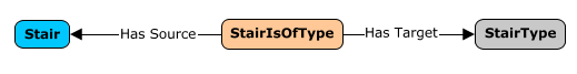
The JsonProperties property that Stair inherited from Element is used to store whatever instance data is needed by the particular StairType instance (width, height and length are likely). This Type modeling is likely to used extensively in both the preliminary design and design phases.
Using Child Elements
Stairs using either a Type or a FormAspect may eventually need to be detailed (detailed modeling could also be done from the start). This detailing is enabled using child Elements. To support this, the Stair class designer will add the mixin class IParentElement as a superclass of Stair (indicating that this Stair can be defined via its children, but not via a breakdown model). For further clarity, thee Stair class designer will subclass PhysicalElementAssemblesChildElements…..
This modeling allows the stair to be defined by any PhysicalElement; the Stair class designer has provided extreme flexibility, but weak “compile-time type checking”. This compromise is common in BIS.
Stair Using Children Inheritance Diagram
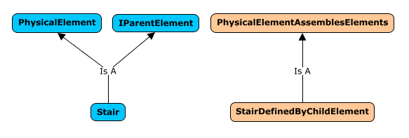
Stair Using Children Instance Diagram
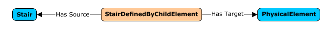
All of these modeling approaches will all be available through the schema, but will never be used simultaneously by the same instance.
Simple Data Additions – Aspects & Relationships
Other schema designers can create Aspects that can be attached to Stair or one of its superclasses. The Stair class designer does not need to predict all Aspects that may need to be associated with Stair in the future. Users may take advantage of these Aspects at any point in time.
Relationships – like Aspects – can be defined for the Stair class (and its superclasses) without any knowledge by the Stair class designer. Users may take advantage of these Relationships to other Elements at any point in time.
Schema Versioning and Generations
Schema Versions
As products (applications and services) evolve, they will require new and/or different data organization. As the data organization is defined in schemas, schemas must change to support the newer products. This leads to the need to clearly version schemas.
Schema versioning should not be confused with data versioning. Data will be changed very frequently by users. Schemas will change less frequently, only as improved products that require new data organization are released.
Need for Schema Upgrade Strategy
Most iModels are accessed by multiple products. Products will synchronize through iModelHub. The data that products store will be organized by a single (versioned) set of schemas.
One potential strategy to ensure that all the products can work with the schemas in an iModel is limit the products used to the subset of products that are written for the exact versions of the schemas that are in the iModel. If there is a desire to update a product and that update requires newer schemas, then all of the products accessing the iModel are updated simultaneously. This quickly becomes an untenable strategy when more than a very small number of applications and services are used. For that reason, our schema evolution strategy needs to accommodate non-aligned product releases.
The BIS schema upgrade strategy is based on the concept of Generations which are closely related to Minor Schema Upgrades and Major Schema Upgrades.
Some services that do not directly work with iModels will use BIS semantics. These services will also benefit from versioning strategy described in this section.
EC Schema Versioning
There are clear EC schema versioning rules that are based on the repercussion of changes made during a schema upgrade.
Minor Schema Upgrades
Minor schema upgrades are schema changes that don’t break compatibility with applications written for the previous schema.
Minor schema upgrades can ONLY include:
- The addition of optional classes.
- The addition of optional properties.
- The addition of Kinds of Quantities
- The addition of Categories
- Changes to items that don’t affect code (or meaning), such as label changes, description changes and other changes that just affect presentation.
Minor schema upgrades may NOT include:
- The removal of classes.
- The removal of properties.
- The change of class definition (for example, changing the base class).
- The change of property definition (for example, changing the type).
The change of relationship constraints, cardinality or strength.
Major Schema Upgrades
Major schema upgrade can potentially break compatibility with applications written for the previous schema. Any schema change that does not qualify as minor is major. Some examples of changes that trigger a major schema change are:
Removal of a class.
- Removal of a property.
- Renaming of a class or property.
- Changing of a base class in a way that makes the former parent class no longer a direct ancestor (currently any change in parent class is a major schema upgrade).
- Changing the type of a property.
- Changing relationship constraints or cardinality.
Schema Version Numbers
To be able to detect schema changes that are backward compatible for reading data, but not backward compatible for writing data, EC Schema version numbers have 3 parts
| Digit | Meaning | Changes Imply |
|---|---|---|
| 1st (read) | Generation of the schema that guarantees (if digit matches) that newer schemas’ data can be read by older software. | No compatibility can be assumed for previous schema versions (breaks read and write logic) |
| 2nd (write) | Sub-generation of the schema that guarantees (if digit matches) that newer schemas’ data can be written by older software. | Additions have been made to the schema which break existing write logic (but not read logic) |
| 3rd (minor) | Least significant version number that increments with read/write compatible additions. | Additions have been made to the schema, but they do not break existing schema read or write logic. |
This 3-digit system is a little different from the standard 3-digit versioning strategy described at Semantic Versioning. This is due primarily due to Semantic Versioning pertaining to APIs and code instead of schemas.
The Middle Version Number
The second write version number is a bit difficult to understand - how does it correspond to a Major Schema Updates and Minor Schema Updates?
Effectively the second write version number is updated when a schema upgrade can be considered a major update for writers of the data, but is only a minor update for readers of the data.
For example, consider in schema 1 that we have a Student class that stores grades and has (double) properties:
- Language
- Math
- Science
- Music
- Overall GPA (an average of the previous 4 properties)
If schema 2 adds to Student a double property Psychology, the meaning of Overall GPA changes slightly and hence, applications written for Schema 1:
- Can still safely read all the values that were in schema 1
- Cannot modify any values that were in schema 1 because they will likely set Overall GPA incorrectly.
Updating data for a schema update with a write version change usually requires some custom logic. This should not be surprising as the previous data was written by applications that are not write-compatible with the newer schema.
Examples of Write incompatible changes
- Adding a Not Null or Unique constraint on a new property in an existing class
- Adding a new Navigation Property with a Foreign Key constraint to an existing class
There are other examples of write incompatible changes which, however, are prohibited by the software because they would modify how EC content is mapped to the database (which is generally not allowed):
- Adding a Not Null or Unique constraint to an existing property
- Adding a new unique index to an existing class
Adding a Foreign Key constraint to an existing Navigation Property
Application Schema Compatibility Logic
The general logic for an application written for a particular version of a schema working with a repository that potentially has a different version of the schema would be:
If schema in the repository is newer (or same):
- If first digit matches, app can safely read.
- If first two digits match, app can safely write (and read).
- If no digit matches, the schema is of a different generation and the application cannot do anything.
- If schema in the repository is older:
- If first two digits match, app can upgrade repository schema without breaking read or write for other apps.
- If only first digit matches, app can upgrade repository schema, but upgrade will prevent some older apps from writing.
- If no digit matches, the schema is of a different generation and the application cannot do anything.
BIS Generations
Major schema upgrades are eventually required in any evolving product or system. If every Domain was allowed to select when its major schema updates occurred, then – as BIS will have a large number of Domains – nearly every BIS release would contain some major schema updates.
To avoid the confusion of continual major schema updates, BIS Generations are defined and major schema updates are restricted.BIS Generation
A BIS Generation consists of a series of releases during which major schema upgrades are not allowed for any Domain. As minor schema upgrades will not break application compatibility, any application based on the same BIS Generation can work together through an iModel.
The 3-digit schema version numbers of EC Schemas (Read.Write.Minor) allow two types of Major schema version to be defined. As an emergency outlet, it will be allowed to change the Write version number within a Generation, but this will be severely discouraged. To ensure that changes to the Write version number are taken seriously enough, OCTO review is recommended for any such Write changes.
It must be remembered that repositories can be updated from one Generation to the next Generation without loss of data. It is the individual applications that can only work with repositories from a single Generation.Generation Schema Numbering
As BIS Generations are tightly aligned with major schema upgrades, it is natural to use the Generation number as the major schema version for all BIS Domains. The numbering for all schemas in a Generation is Generation.Write.Minor, where all the Generation numbers in a BIS repository match. The Write numbers will almost always all be 0. The Minor numbers can and will vary.
Schema Production Status
Schema Evolution
Schemas that have been released for production use in end-user workflows evolve over time as new capabilities are added and other improvements are made. To manage and track this schema evolution, schema versioning is used. See Schema Versioning and Generations for details on BIS’s schema versioning strategy.
A single version of a schema that has not yet been released for production also evolves. A pre-production schema is expanded and modified as it goes through periods of development and field testing before being released for production. Also, after a schema is released into production workflows, it may become deprecated. This page describes the management and tracking of this non-version axis of schema evolution.
Motivation
The primary motivation for formally tracking the production status of schemas is to ensure they are not used contrary to the way the schema author intended. The mechanisms described on this page:
- Enable the schema author to clearly define the intended usage of the schema.
- Enable the iModel creator to clearly define the intended usage of an iModel.
- Provide a mechanism to ensure that the schemas in an iModel have an intended usage that is compatible with the iModel’s intended usage.
ProductionStatus Custom Attribute
The intended use of a schema is tracked through the ProductionStatus CustomAttribute. The ProductionStatus CustomAttribute may be placed on any BIS schema. That CustomAttribute has a SupportedUse property that can have one of these values:
| Value | Meaning |
|---|---|
| Production | This schema is suitable for use in production workflows. Data created using this schema will be supported long-term (possibly through transformation). |
| FieldTesting | This schema is suitable for field testing of production workflows. Data created using this schema may not be supported long-term and may not be upgradable. |
| NotForProduction | This schema is under development and should never be used for production workflows. Data created with this schema is not supported and may not be upgradable. |
| Deprecated | This schema is no longer recommended for production workflows. Better alternatives exist and should be used instead. |
iModel Support for ProductionStatus
The iModel ecosystem uses the ProductionStatus of schemas to determine if a schema can be loaded into an iModel.
iModel ProductionStatus Setting
To determine whether a schema with a ProductionStatus other than Production can be loaded into an iModel, the iModel technology stack needs to understand the intended use of the iModel. For this reason, every iModel contains a ProductionStatus setting that declares the suitability of the iModel for production use. The possible values for this setting correspond to those in the ProductionStatus custom attribute, although their definitions are slightly different:
| Value | Meaning |
|---|---|
| Production | This iModel is suitable for use in production workflows. |
| FieldTesting | This iModel is suitable for field testing of production workflows. Data contained in it may not be supported long-term. |
| NotForProduction | This iModel is suitable for developer testing only and should never be used for production workflows. Data contained in it will not be supported long-term. |
| Deprecated | (this value should not be used for iModels) |
The iModel’s ProductionStatus setting is stored in the be_prop table as follows:
| Column | Value |
|---|---|
| NameSpace | “dgn_Db” |
| Name | “ProductionStatus” |
| StrData | “Production”, “FieldTesting” or “NotForProduction” |
The ProductionStatus value of the iModel is set when the iModel is created.
Compatibility of Schemas for iModels
At schema load time, the iModel technology confirms that the schema’s ProductionStatus is compatible with the iModel’s ProductionStatus. The compatibility of these settings is shown below:
| iModel ProductionStatus | Compatible Schema ProductionStatus |
|---|---|
| Production | Production, Deprecated |
| FieldTesting | Production, FieldTesting, Deprecated |
| NotForProduction | Production, FieldTesting, NotForProduction, Deprecated |
The attempted loading of a schema that is not compatible will result in a schema load failure.
Changing of iModel ProductionStatus
An iModel’s ProductionStatus can conceptually be “downgraded” as follows:
| iModel ProductionStatus | Compatible Downgraded ProductionStatus |
|---|---|
| Production | FieldTesting, NotForProduction |
| FieldTesting | NotForProduction |
| NotForProduction | (no further downgrade is possible) |
In the future, the ability for a user to downgrade the ProductionStatus of an iModel will be provided.
An iModel’s ProductionStatus can conceptually be upgraded as follows:
| Upgraded iModel ProductionStatus | Condition |
|---|---|
| Production | No schemas of ProductionStatus FieldTesting or NotForProduction |
| FieldTesting | No schemas of ProductionStatus NotForProduction |
| NotForProduction | (not possible as upgrade) |
In the future, the ability for a user to upgrade the ProductionStatus of an iModel will be provided.
Physical Units in BIS
BIS and iModels always use a well defined system of physical units.
Physical Units must be SI Base Units or SI Derived Units
All physical property values (including geometry) in a BIS schema must be either:
- SI Base Units (m, kg, s, A, K, mol, cd)
- SI Derived Units without prefixes (Hz, rad, sr N, Pa, J, W, C, V, F, (Omega), S, Wb, T H, C, lm, lx, Bq, Gy, Sv, kat)
It is therefore possible to perform mathematical operations on physical values without considering units:
Mass = Density * Volume; // no unit conversions necessary
Note: in iModels, all coordinate data is stored in meters.
Units with prefixes, such as kilometer, millimeter, kilowatt and millivolt are not allowed.
Angle Units
Angle units are radians, as that is the SI Derived Unit for angles. Similarly the units for solid angles are steradians.
This may seem awkward, as “90” is a more recognizable value than “1.5707963267948966192313216916398” However, note that storage units are not directly presented to users.
Radians are used to permit consistent mathematical computations.
For example:
(luminous flux in lumens) = (luminous intensity in candela) * (solid angle in steradian)(energy in Joules) = (torque in N-m) * (rotation in radians)
Exception for Roll, Pitch and Yaw
Roll, Pitch and Yaw (in GeometricElement3d and ViewDefinition3d, AuxCoordinateSystem3d) are handled specially. They are defined in degrees and declared as unitless in the EC schema.
Similarly, these properties are defined in degrees and declared as unitless in the EC schema:
- Angle in AuxCoordSystem2d
- Rotation in GeometricElement2d
- LensAngle in ViewDefinition3d
- RotationAngle in ViewDefinition2d
SI Units do not Apply to Names and Text
The SI units requirement only applies to numeric physical and geometry properties; it does not apply to text properties. “90-Degree Elbow” is an acceptable text value.
BIS Schema Validation
The variability and potential magnitude of schema rules lead to the need for quality control and long-term maintainability over BIS schemas.
BIS uses EC v3
BIS is defined using EC v3. EC v3 is a more clearly defined and rigorous version of the EC that has been used widely in Bentley over the past 10+ years.
BIS is modularized into a set of interrelated domains (each expressed in a separate ECSchema) that are consistent, coordinated and constrained to maximize the functionality of the entire BIS-based ecosystem. Some flexibility that is available in “raw” EC is not available in BIS. For example, all ECClasses defined in domain ECSchemas (other than BisCore itself) are required to sub-class from some ECClass in BisCore. Other BIS rules are documented at BIS Schema Validation.
Unless noted otherwise, all references to “schema”, “class” and “property” in this document refer to ECSchema, ECClass and ECProperty.
Validation Rules
BIS Schemas are validated against a set of rules. If one rule is violated, the whole schema will fail validation.
The rules are broken into the different parts of the Schema they are validated against.
General (Schema) Rules
BIS-001
A schema must load and pass EC3.1 spec validation.
BIS-002
A schema’s ECXML version must be at least, 3.1.
-
BIS-003
A schema may not reference any EC2 or EC3.0 schemas.
BIS-004
A schema must specify a three-part version number
The version number must be in the format RR.WW.mm (that is, Read.Write.Minor).
Each version component must be zero-padded to two digits (e.g. 01.02.00).
BIS-005
A schema reference must specify a three-part version number (in the same format described above).
BIS-006
If the schema contains ‘dynamic’ (case-insensitive) in its name it must apply the CoreCA:DynamicSchema custom attribute.
BIS-007
Classes within the same schema cannot have the same display label.
BIS-008
A schema should not reference a deprecated schema.
BIS-009
An alias in the schema reference must be the same as the alias defined by the schema.
Class Rules
BIS-100
Properties within the same class and category cannot have the same display label.
BIS-101
Classes not within the BisCore, Functional, or Generic schema cannot applied bis:ClassHasHandler.
BIS-102
Class should not derive from a deprecated class.
BIS-103
Class should not have deprecated properties.
BIS-104
Class should not have properties which are of deprecated struct types.
BIS-105
Classes should not use custom attributes that are deprecated.
Custom Attribute Classes
BIS-400
Custom Attribute classes must not have base classes.
Entity Class Rules
BIS-600
Entity classes must derive from the BIS hierarchy.
BIS-601
Entity classes may only derive from one base Entity class.
BIS-602
Entity classes may not inherit a property from more than one base class.
BIS-603
A mixin property cannot override an Entity property inherited from a base Entity class.
BIS-604
If any aspect (ECClass which derives from bis:ElementMultiAspect) exists, there must be a relationship that derives from the bis:ElementOwnsMultiAspects relationship with this class supported as a target constraint.
Treated as warning if the schema has the CoreCA:DynamicSchema CA applied.
BIS-605
If any aspect (ECClass which derives from bis:ElementUniqueAspect) exists, there must be a relationship that derives from the bis:ElementOwnsUniqueAspect relationship with this class supported as a target constraint.
Treated as warning if the schema has the CoreCA:DynamicSchema CA applied.
BIS-606
Entity classes cannot implement both bis:IParentElement and bis:ISubModeledElement.
BIS-607
Entity classes cannot subclass the following classes:
bis:PhysicalModel
- bis:SpatialLocationModel
- bis:GroupInformationModel
- bis:InformationRecordModel
- bis:DefinitionModel
- bis:DictionaryModel and bis:RepositoryModel are the only classes allowed to subclass bis:DefinitionModel
- bis:DocumentListModel
-
BIS-608
Property overrides cannot change the persistence unit.
BIS-609
Subclasses of bis:Model cannot have additional properties defined outside of BisCore.
BIS-610
Entity classes may not subclass deprecated classes.
BIS-611
Entity classes should not derive from deprecated mixin classes.
KindOfQuantities
BIS-1000
Kind Of Quantities must not use ‘PERCENTAGE’ or other unitless ratios.
BIS-1001
Kind Of Quantities must use an SI Unit for their persistence unit.
BIS-1002
Kind Of Quantities must not have duplicate presentation format.
Mixin Rules
BIS-1100
Mixin classes may not override an inherited property.
Properties
BIS-1300
Properties should not be of type long. These properties should be navigation properties if they represent a FK or be of type int or double if they represent a number.
BIS-1301
Properties within the same class and category cannot have the same display label.
BIS-1302
Properties must use the following supported ExtendedTypes:
BeGuid
- GeometryStream
- Json
BIS-1303
Properties must not use CustomAttribute bis:CustomHandledProperty unless CustomAttribute bis:ClassHasHandler is defined on their parent class (not derived from a base class).Relationship Classes
BIS-1500
Relationship classes must not use the holding strength.BIS-1501
Relationship classes must not have a source constraint multiplicity upper bound greater than 1 if the strength is embedding and the direction is forward.BIS-1502
Relationship classes must not have a target constraint multiplicity upper bound greater than 1 if the strength is embedding and the direction is backward.BIS-1503
Relationship classes must not have an abstract constraint if there is only one concrete constraint set.BIS-1504
Relationship classes must not have an bis:ElementAspect target constraint (or source constraint if direction is backwards), unless they derive from bis:ElementOwnsUniqueAspect or bis:ElementOwnsMultiAspects.BIS-1505
Embedding relationships should not have ‘Has’ in the class name.BIS-1506
Relationship Constraint should not use a deprecated class or mixin as a constraint class.BIS-1507
Relationship Constraint should not use a deprecated class or mixin as an abstract constraint.BIS-1508
Relationship Constraint should not use constraint classes which derives from a deprecated base class or deprecated mixin classes.BIS-1509
Relationship Constraint should not use abstract constraint which derives from a deprecated base class or deprecated mixin classes.Struct Classes
BIS-1700
Struct classes must not have base classes.
Domains
The following domains exist in BIS
Core
BisCore
Functional
Generic
Linear Referencing
Shared across disciplines
AECUnits
SpatialComposition
ClassificationSystems
Building discipline
Building Spatial
Standard Schemas
CoreCustomAttributes
ECDbMap
Formats
Units
BIS Glossary
Key BIS terms used in this documentation are defined on this page.
| Term | Description |
|---|---|
| BIS Repository | An information repository with semantics and structure defined by BIS. iModels are an implementation of a BIS Repository. |
| BIS | Base Infrastructure Schemas. A coordinated family of schemas for modeling built infrastructure (e.g. buildings, roads, bridges, factories, etc.) BIS also addresses concepts needed for infrastructure-related workflows (e.g. documents, drawings, requirements, issues, etc.). |
| BisCore | The base BIS Domain for BIS. All ECClasses in any other Domain must derive (directly or indirectly) from a BisCore class. |
| Category | A property of a GeometricElement that “categorizes” its geometry. Every GeometricElement is assigned to one and only one Category. The visibility (on/off) of a category may be controlled per-view. Categories are similar to levels in DGN, layers in DWG, and categories in RVT. |
| Class | See ECClass . |
| Code | A synonym for CodeValue . See Codes . |
| CodeScope Property | A navigation property of Element that points to an Element that indicates the scope for uniqueness for the CodeValue. See Codes . |
| CodeSpec | A “Code Specification” that specifies how a Code is encoded and decoded. See Codes . |
| CodeSpec Property | A navigation property of Element that points to a CodeSpec that specifies how the Code is encoded and decoded. See Codes . |
| CodeValue Property | A nullable string property of Element that holds a human-readable identifier of the Entity that the Element represents. See Codes . |
| DefinitionElement | A subclass of InformationContentElement that holds information that helps define other Elements and is intended to be referenced (i.e. shared) by multiple of those Elements. |
| Digital Twin | A digital representation of some portion of the real world. A Digital Twin should be designed to be used by multiple applications (in contrast to application-specific “silo” databases). A complete Digital Twin is normally a federation of data from multiple repositories (e.g. a BIS Repository such as an iModel, plus Reality Data services, plus IoT data services, plus Asset Lifecycle Information Management services, etc.) |
| Domain | A named set of ECClasses that define the information for a particular discipline or field of work. All classes in a Domain ultimately must derive from a BisCore class. The ECClasses for a Domain are defined in a ECSchema file, an hence the terms Domain and ECSchema are often used interchangeably. |
| DrawingModel | A 2d model that holds drawing graphics. DrawingModels may be dimensional or non-dimensional. |
| EC | An abbreviation for Entity Classification. This prefix is used to refer to the metadata system of BIS. |
| ECClass | A named set of properties and relationships that defines a type of object. Data in BIS Repositories are defined by ECClasses. |
| ECProperty | A named member of an ECClass. |
| ECRelationship | A named type of relationship and cardinality between instances of ECClasses. |
| ECSchema | A named group of ECClasses and ECRelationships. |
| Element | The base class in BIS for an Entity with a Code. An Element is smallest individually identifiable building-block for modeling in a BIS Repository. There can be different subclasses of Element corresponding to different Modeling Perspectives. Multiple Elements can be related together to model different Perspectives of an Object. |
| ElementAspect | A BIS class that adds properties and/or relationships to a single Element to add more detail. ElementAspects can be used, for example, to record information that is only be needed in certain situations or in some stages of the Element’s lifecycle. An ElementAspect is owned by, and thus is deleted with, its owning Element. |
| ElementId | A 64-bit unique Id for an Element within a BIS Repository. For iModels, ElementIds are assigned by combining a 24-bit BriefcaseId with a 40-bit sequentially assigned value. |
| ElementOwnsChildElements | Relates an Element to child Elements which represent parts of the Entity modeled by the parent Element. Element subclasses can either allow the use of child Elements to model its parts, or allow use of the ModelModelsElement relationship with another Model to express a detailed model of the parts, but not both. |
| Entity | A portion of a real-world Object that is relevant for a given Modeling Perspective. The complete Object is the sum of its Entities. For example, an Entity can be the role that the Object plays in a particular system. |
| FederationGuid | An optional 128 bit Globally Unique Identifier for the Entity that an Element models. Generally it is intended that FederationGuids are assigned by external systems and are used to federate Elements to their external meaning. Within a BIS Repository, FederationGuids must be unique, and thus can be used as secondary identifiers for an Element (when they are present). |
| GeometricElement | A subclass of Element that can include geometry (in its GeometryStream property.) Only GeometricElements are visible in Views. |
| GeometricModel | A subclass of Model that can hold GeometricElements. |
| GeometryPart | A named GeometryStream that can be shared by many GeometricElements. |
| GeometryStream | A collection of geometric primitives that describes the geometric properties of a GeometricElement. Individual members of GeometryStream may be in different SubCategories and may reference GeometryParts. |
| Granularity | The scale or level of detail of Elements in a Model. |
| iModel | A BIS Repository implemented as a distributed database using SQLite and iModelHub. See iModels are the most common BIS Repository. Many copies of an iModel may be extant simultaneously, each held in a Briefcase and synchronized via ChangeSets from iModelHub. |
| InformationPartitionElement | An Element in the RepositoryModel that identifies a portion of the BIS Repository that models a Subject from the Partition’s Modeling Perspective. A Partition must be the child of a Subject, which can have multiple specialized Partition Elements (e.g. PhysicalPartition, FunctionalPartition) as children. |
| Model | A set of Elements used to describe another Element (its ModeledElement) in more detail. Every Element is contained in one and only one Model via a ModelContainsElements relationship. In this manner, Models form a hierarchy of Elements. There are many subclasses of Model (e.g. PhysicalModel, FunctionalModel, etc.) |
| ModelContainsElements | A relationship that enforces that each Element belongs to exactly one Model. |
| ModeledElement | An Element that is broken down in more detail by a Model. Note that the name of a Model is the name of its ModeledElement, and the ParentModel of a Model is the Model of its ModeledElement. |
| Modeling Perspective | A way of “looking at” or “thinking about” an Object, e.g. functional, physical, spatial, financial, etc. |
| ModelModelsElement | A relationship that relates a Model to the Element which the Model models in more detail. In other words, the Model breaks-down the coarser-grained Element into a more-detailed Model consisting of finer-grained Elements. This relationship allows BIS to cohesively model reality at multiple granularities within the same BIS Repository. |
| Object | A real-world object that may be physical or non-physical. Not used to refer to instances of ECClasses. |
| Perspective | See Modeling Perspective |
| PhysicalModel | A subclass of SpatialModel for the physical perspective that holds PhysicalElements and SpatialLocationElements. |
| Relationship | See ECRelationship . |
| RepositoryModel | A special Model that is the root of the hierarchy of Models in a BIS Repository. Every BIS Repository has one and only one RepositoryModel, and it is the only Model that does not have a ModelModelsElement relationship to another Element. |
| Schema | See ECSchema . |
| SheetModel | A digital representation of a sheet of paper. Sheet Models are 2d models in bounded paper coordinates. SheetModels may contain annotation Elements as well as references to 2d or 3d Views. |
| Spatial Coordinate System | The 3d coordinate system of a BIS Repository. The units are always meters (see ACS). The origin (0,0,0) of the Spatial Coordinate System may be oriented on the earth via an EcefLocation . |
| SpatialModel | A subclass of GeometricModel that holds 3d Elements in the BIS Repository’s Spatial Coordinate System. |
| SpatialViewDefinition | A subclass of ViewDefinition that displays one or more SpatialModels. |
| SubCategory | A subdivision of a Category . SubCategories allow GeometricElements to have multiple pieces of Geometry that can be made independently visible and styled. It is important to understand that a SubCategory is not a Category (i.e. Categories do not nest) and that a SubCategory always subdivides a single Category. |
| Subject, Root | The primary Subject in the RepositoryModel that names or briefly describes (in text) the real-world Object that the repository is modeling. There is always one and only one Root Subject in a repository. The Root Subject and its child Subjects effectively form a table of contents for the repository. |
| Subject | An Element in the RepositoryModel that names or briefly describes (in text) a significant real-world Object that the repository is modeling. Every Subject is either the Root Subject, or a child of another Subject. |
| ViewDefinition | A subclass of DefinitionElement that holds the persistent state of a View. |
BIS Naming Guidelines
Rules and Recommendations
The following rules and recommendations [rec.] should be honored when devising BIS names. This include Domain, Schema, Namespace, Class and Properties names as well as aliases.
NOTE: The items below are not ordered by importance but rather around related concepts.
General
BIS naming convention is deliberately more restrictive than EC naming: All BIS names are valid EC names but not all EC names are valid BIS names.
| Description | Note | |
|---|---|---|
| Rule | Only use alphanumeric characters | |
| Rule | Do not use an underbars in names | Don’t use underbars even if it aids readability: Use OrderLineItem not Order_LineItem |
| Rule | Names may not start with a number | E.g. 3dGeometry is not allowed |
| Rule | Names may not differ only by case | E.g. If there’s already a name called Pricelist then you may not define a new one called PriceList |
| Rule | Use PascalCase names | PascalCase means words are concatenated with the first letter of each word capitalized. E.g. OrderLineItem |
| Rule | Use United States Spelling | E.g. Organization not Organisation |
| Rec. | Use the most widely accepted and descriptive name possible | Consult the current thesaurus before creating new words. |
| Rec. | Use a single word that describes the entity | E.g. Person rather than HumanBeing |
| Rule | Don’t add superfluous terms | Don’t use two nouns if one can equally express its meaning. |
E.g. Vehicle rather than TransportationVehicle.
For relationships we can often infer the type of target from the name of the source. So, use PhysicalElementIsOfType rather than PhysicalElementIsOfPhysicalType (because the element cannot be of any type other than Physical!) | | Rec. | Do not add any unnecessary prefixes or suffixes to an entity | Especially terms like Object, Instance, Entity, and Property.
E.g. Use Note not NoteEntity (for a class name) or NoteProperty (for a property name). | | Rec. | Words should be less than 30 characters | | | Rec. | Use abbreviations and acronyms with care | Use abbreviations and acronyms only where they are common and completely unambiguous. If the abbreviation/acronym is not well known, don’t use it!
Try to limit the use to those that appear in the list of abbreviations and acronyms
and don’t use those listed in the “don’t use” section.
Two letter acronyms have both letters capitalized, provided that each letter represents a different word.
E.g. UI (“User Interface”) and IO (“Input/Output”) because both words are capitalized, but Db because “Database” is one compound word.
Three or more letter acronyms have only the first letter in capital case.
E.g. Html or Guid
Abbreviations of a single word have only the first letter in capital case.
E.g. Id (“Identification”) | | Rec. | Use numbers with care | Avoid names such as One21 and Door2Door
A well-known exception is for terms 1d, 2d, and 3d (dimensions). These may be used to form new terms provided they don’t break the rule stating that Names may not start with a number
.
E.g.Acceptable names are Spatial1d, Model2d | | Rec. | Use special words with care. | Specifically, make sure that the semantic meaning of the special term is well understood._
E.g.List, Item, Set, etc…
If it isn’t an Aspect, don’t put Aspect in the name. | | Rule | Do not use New, Old, Tmp, or Temp | What seems “new” when you do it will become “old” when you make the next change. | | Rec. | Avoid the use of ‘Base’ in class names | E.g. use RasterModel instead of RasterBaseModel | | Rec. | Avoid using the organization’s name | If prefixes are needed, give preference to the domain rather than the organization.
E.g. Use TransportElement rather than ExorElement | | Rec. | Avoid using product names | E.g. Avoid prefixes like eB, OpenPlant, STAAD, Dgn, ConnectedProject | | Rec. | Avoid domain names in the term | E.g. PlanningElement, ConceptualElement, PlantElement, PlantArea, and Area | | Rec. | Avoid using version numbers or generation names | E.g. V8iFile | | Rec. | Favor instances over definitions | I.e. if you need to distinguish between an Entity Definition and an Entity Instance and there are no suitable words that can distinguish them, suffix the definition rather than the instance: user will work with instance more often than definitions_
E.g. Use AttributeDefinition for the definition and Attribute for the value.
Note: The ECProperty is an example where this recommendation is not being followed. There are no plans to change that - Sorry. |
ECSchema / BIS Domain Names
| Description | Note | |
|---|---|---|
| Rule | All EcSchema/BIS Domain Names must be registered with BIS workgroup to avoid conflicts. This includes the aliases. |
E.g. BisCore (schema name) and bis |
See list of BIS Schemas | | Rule | BIS Schema aliases must be in lowercase | | | Rule | BIS Schema aliases must be less than 7 characters long | |
Class
| Description | Note | |
|---|---|---|
| Rule | Use singular form | E.g. File not Files |
| Rule | When combining terms, arrange them in increasing order of significance | E.g. CableCar, AnalogWaterMeter |
Exceptions: 2d and 3d because names can’t start with numerals | | Rec. | Names of direct or indirect specializations of bis:ElementAspect should end with Aspect. | | | Rec. | Do not use prepositions such as Of, With, On, An, In, From, etc… | |
Property (including “Navigation” Properties)
| Description | Note | |
|---|---|---|
| Rule | Use the plural form of the name when the attribute is a collection, otherwise use the singular form. | Document.AddedBy (a document can be added by a single person) but can have many notes, so Document.Notes |
| Rec. | Try to create attributes with the same name as their underlying type | Document.Lock is of type Lock |
Exception: When the entity has more than on attribute of that type, or when it aids in readability: Document.AddedBy instead of Document.Person | | Rec. | Don’t include the primitive datatype (int, string) with the name | Exception: Dates. Since Date is both a data type and a more meaningful noun, something like DateAdded would be acceptable but NoteBlob would not be. | | Rule | Don’t include the attribute owner name in the attribute name | E.g. Document.Id not Document.DocumentId and Person.Name not Person.PersonName | | Rule | Prefix Boolean names with Is, Has, Can, May | E.g. IsUnderChange, HasOtherRevision, MayChange | | Rule | When the field represents a bit mask, use the plural form of the word | E.g. StateHints, HasFlags | | Rule | For NavigationProperties, prefer to use the name of the related ECClass as the property name | If further qualification is needed, consider prefixing words from the role label. |
Relationship
Relationship naming rules are difficult because of competing concerns. It is important for relationship class names to be clear and unambiguous so that the purpose and constraints of the relationship can be understood. However, it is also important to be cognizant of the number of characters in the relationship class name since that is what a developer or power user will have to type in when using ECSQL. Names that are too long are frustrating, but vague names are also frustrating. The rules and recommendations below try to balance these concerns:
| Description | Note | |
|---|---|---|
| Rule | Use Source-Verb-Target | E.g. ElementOwnsUniqueAspects, OrganizationSellsProducts |
In most cases, the “source/target” will simply be the name of the object. In those cases, the addition of an adjective can be helpful: Child in ElementOwnsChildElements |
| Rule | Fully specify the source constraint
In general, use the full class name of the source constraint for the source portion of the relationship name. In some cases, the suffix of the source constraint class name can be dropped if it doesn’t help with understanding the purpose of the relationship. | E.g. “PhysicalElementIsOfType”, “PhysicalSystemServicesElements” |
| Rule | Try to use a specific action-oriented verb
Verbs like aggregates, holds, groups, represents, services are more action-oriented while verbs like has or relates to are more passive and don’t identify the purpose of the relationship. | E.g. “DrawingGraphicRepresentsElement”, “PhysicalElementServicesElements” |
| Rule | Use verbs that are consistent with relationship strength | - Owns, Contains, or Aggregates implies embedding
- Represents or Groups implies referencing
See list of relationship strengths |
| Rule | Shorten the target portion if possible
Use the role within the relationship or a shortened form of the target constraint class. | E.g. “PhysicalElementIsOfType”
In this case, fully specifying the target constraint of PhysicalType would make the relationship class name longer without adding much clarity since the source constraint gives a strong hint as to the target constraint. |
| Rule | The relationship name should indicate the multiplicity
The source is always singular and the target indicates multiplicity. | E.g. ElementOwnsChildElements (1:N), ElementHasLinks (N:N), PhysicalElementIsOfType (N:1) |
| Rule | Don’t use conjunctions
Do not use a singular noun or verb, even if it clearly defines a relationship. Always use noun-verb-noun | E.g. Don’t use Marriage or ManAndWoman; use PersonIsMarriedToPerson |
Special Terms in BIS
This section contains rules and recommendations [rec.] related to special terms from the BIS upper ontology
Model
| Description | Note | |
|---|---|---|
| Rule | Model classes must always be suffixes with Model. | E.g. FunctionalModel, PhysicalModel |
Exception: GeometricModel2d, GeometricModel3d |
Element
| Description | Note | |
|---|---|---|
| Rule | Abstract terms should only appear higher in the inheritance hierarchy than concrete terms. | E.g. The term Element is used to suffix some abstract classes. Once Element is dropped from the name – because the class is concrete - it never comes back. |
User-facing classes are normally concrete and we especially don’t want to add superfluous terms to those. | | Rec. | User-facing classes should not be expressed in abstract terms | E.g. Don’t use InformationContentElement when you can use Document |
RoleElement
| Description | Note | |
|---|---|---|
| Rec. | Don’t suffix with Role | E.g. Resource, Asset rather than ResourceRole or AssetRole |
Aspect
| Description | Note | |
|---|---|---|
| Rec. | Suffix with Aspect |
Type
| Description | Note | |
|---|---|---|
| Rec. | Use the term Type for real world types rather than Class or Kind | E.g. FunctionalType rather than FunctionalClass or FunctionalKind |
Summary of Exceptions
The list below contains a summary of all exception.
| Description |
|---|
| The use of 1d, 2d and 3d needs special mention. |
| The section Use abbreviations and acronyms with care states that two-letter acronyms must have both letters capitalized provided that each letter represents a different word. E.g. UI (“Use Interface”) and IO (“Input/Output”) but Db (because the word is Database and not Data Base). 1d is short for One Dimensional – which is two words and should really be abbreviated to OD or 1D. |
| The rule Names may not start with a number states that we cannot start with 1d, 2d and 3d. And lastly Use numbers with care states that we should try and avoid numbers entirely. |
| The rule When combining terms, arrange them in increasing order of significance suggest that 2dDrawing should be used rather than Drawing2d – but this would break the previous rule. |
| So when it comes to 1d, 2d, 3d; only use them after another term and always as lowercase ‘d’. |
| Never use the words OneDimensional, TwoDimensional or ThreeDimensional even if it appears to be more consistent. |
| Class names should use the singular form ; except for relationships – where we want the relationship name to indicate the cardinality . |
Standard Abbreviations, Acronyms, and Naming Rules
Generally, abbreviations and acronyms should only be used where they are commonplace, expected, and unambiguous. Otherwise, avoid them.
Consistency should be the primary goal when naming new concepts in the context of existing ones.
Accepted Abbreviations
| Abbreviation | Word |
|---|---|
| Db | Database |
| Id | Identifier |
Acronyms and Numeronyms
| Acronym | Phrase |
|---|---|
| 1d, 2d, 3d | One-, Two-, Three-Dimensional (note lowercase “d”) |
| Html | HyperText Markup Language |
| EC | Entity Classification |
| IO | Input/Output |
| UI | User Interface |
| Uri | Universal Resource Identifier See http://www.w3.org/TR/uri-clarification . We prefer the term Uri over Url/Urn for the reasons mentioned in the line above. If it is truly an Urn then rather use ‘Code’ |
| I18N | Internationalization |
| L10N | Localization |
Naming rules
| Don’t Use These | Rather Use |
|---|---|
| Desc | Description |
| Geo, Geom | Geometry |
| Uuid | Guid |
| Mngt, Mgmt, etc | Management |
| Url, Urn | Uri |
| Def | Definition |
| Ref | Reference |
Standard Relationship “Strengths” Names
| Name | Description |
|---|---|
| Has, References, RefersTo | Implies referencing |
| IsOf | For indicating instance of type |
| Owns, Contains | Implies embedding |

若有收获,就点个赞吧
0 人点赞
