See discussions, stats, and author profiles for this publication at: https://www.researchgate.net/publication/296196819
Model-Based Operational-Functional Unified Specification for Mission Systems
Conference Paper · April 2016 DOI: 10.1109/SYSCON.2016.7490662
CITATIONS 3
READS 227
2 authors:
Some of the authors of this publication are also working on these related projects:
Agility and Evolution in Model-Based Systems Engineering View project
Model-Based Risk Analysis View project
Yaniv Mordecai Massachusetts Institute of Technology 30 PUBLICATIONS 102 CITATIONS
SEE PROFILE
Dov Dori Technion - Israel Institute of Technology 355 PUBLICATIONS 4,572 CITATIONS
SEE PROFILE
All content following this page was uploaded by Yaniv Mordecai on 06 November 2017.
The user has requested enhancement of the downloaded file.
Model-Based Operational-Functional Unified Specification for Mission Systems
Yaniv Mordecai Faculty of Industrial Engineering & Management Technion – Israel Institute of Technology Haifa, Israel yanivmor@technion.ac.il
Dov Dori Faculty of Industrial Engineering & Management Technion – Israel Institute of Technology Haifa, Israel dori@ie.technion.ac.il
Abstract—Joint architecting, design, and simulation of operational-functional requirements and scenarios on the one hand and system functionality and technological requirements on the other hand is a common challenge in systems engineering. We propose a model-based systems engineering approach that addresses this challenge. The confusion between operational and functional behavior stems from systems engineers’ inherent tendency to adopt a system-centric perspective and employ modeling techniques that are inadequate for the task at hand. Functional models provide a biased perspective on the overarching operational context, while business-process-oriented models provide partial coverage of the system’s architecture—its structure-behavior combination. The problem intensifies when the operational scenario is indefinite and dependent on responsive system behavior and when the operational scenario consists of the utilization of functionality in multiple systems. Operational mission management in various domains utilizes planning, execution, and control functionality in several systems, and copes with the operational-functional distinction.
Keywords—Model-Based Systems Engineering; Object-Process Methodology; Functional Analysis; Operational Analysis; ScenarioBased Design;
I. INTRODUCTION The distinction between systems’ operational and behavioral (functional) perspectives is a common systems engineering concern. The operational perspective, grounded in the problem domain, is business- or operations-related, while the functional perspective, grounded in the solution domain, is system- and purpose-related. Distinguishing between operational and functional requirements, specifications, and design is difficult, and it poses a challenge to systems engineers, which surfaces time and again in both new and ongoing systems engineering and operation programs. System models are inherently system-centric, and are therefore biased towards the functional-architectural perspective: They describe the environment around the system and the way the system behaves from the system’s point of view. Systems engineers tend, and are often committed, to introducing the system or subsystem they own to benefit their stakeholders and interest groups. For instance, several companies involved in a development program will each introduce the system around the assets—technologies, services, system components, etc.— they own in the program, focusing on the functionality and value
that their assets provide. Finally, traditional systems engineering standards have difficulties expressing operational requirements in conjunction with functional design [1]. While functional system-centric models are biased towards solution-oriented local perspectives, business-oriented procedural specifications, using approaches such as business process modeling (BPM), scenario-based design (SBD), and operational viewpoints in architectural frameworks (AF), lack the anchoring to actual assets, solutions, and capabilities of the systems that facilitate these scenarios. These descriptions help clarify the end-to-end, operational context, the business justification or rationale, or the scoping and clarification of the problem domain, but they can hardly be used to specify systems architecture. The need for a model that combines scenarios and functions has been well understood [2]. Model-based approaches founded on modeling languages such as UML or SysML propose separate views for business- or customer-oriented visualizations [3], [4], including the Use Case Diagram and Activity Diagram, to some extent, and the SysML-unique Requirements Diagram. SysML also proposes separate views for functional specifications, including Block Diagrams, Statecharts, and Sequence Diagrams. This separation is deliberate and is part of UML’s aspect decomposition approach. While Use Cases are primarily intended for operational, customer-related scenario descriptions, they are often misused for describing system functions rather than the scenarios in which external actors utilize these functions [5]. In addition, their affinity to other aspects of UML models is loose and unstructured [6]. In this paper, we propose Operational-Functional Unified Specification, OFUS – a model-based approach to accommodate and specify operational aspects in conjunction with functional aspects in a coherent, unified, and synergistic model. The framework is based on the ISO-standardized Object-Process Methodology, OPM (ISO-19450), a holistic model-based systems engineering (MBSE) paradigm for complex systems and processes [7], [8]. The use of OPM provides for the proposed modeling patterns to be seamlessly integrated into any OPM-based system model and enrich it with the benefits of OFUS. The OFUS approach is the result of a conceptual modeling study of mission systems. A mission is an operational scenario
This research was supported by the Gordon Center for Systems Engineering at the Technion – Israel Institute of Technology.
in which the system-of-interest (SoI) plays some role. When the SoI is specified and designed, it is difficult to distinguish between mission-related operational behavior and systemfunctional behavior. In order to tackle this problem, we have developed OPM-based modeling patterns that capture the operational scenario alongside the system’s functionality. We demonstrate this pattern for a challenging case of search & rescue operations. This case in point is of special interest because it begins with a mission planning scenario, followed by a mission performing scenario. The two scenarios rely on mission planning and executing functionality. The rest of this paper is organized as follows. Section II provides a Literature Review. It discusses relevant topics including scenario-based design (SBD) and OPM. Section III introduces OFUS: Operational-Functional Unified Specification. Section IV discusses the OFUS Applied to Search and Rescue Mission System. Section V includes Discussion and Conclusion as well as future research options.
II. LITERATURE REVIEW
A. Scenario-Based Design
Scenario-based design (SBD) [9], [10] is an informal usageoriented software design technique that focuses on user experience and usage scenarios, in which use of software systems is made. This is a departure from the functional specification approach, which caters to solution-oriented design [11]. User interaction scenarios are described with twodimensional, paper-and-pencil sketches, intended to vividly capture the essence of the interaction being designed, much like the way machine drawings are used for physical design. SBD had evolved during the mid-1990’s through mid-2000’s, spearheaded by Carroll, Rosson, and others. This approach was criticized for its inability to truly capture user goals on the one hand, and cater to functional design, which is eventually needed to promote the SoI, on the other hand [2]. Integration of SBD was proposed mostly for embedded, concurrent, and real-time system modeling, mostly through integration with statecharts [12]–[15].
B. Operational Viewpoints in Architecture Frameworks
The US Department of Defense’s Architecture Framework (DoDAF) includes an operational viewpoint (OV), which captures and provides for the analysis of operations-supporting tasks and activities, operational elements, and resource exchange [16]. OV models, which are related to capability viewpoint (CV) models, allow for mapping system capabilities to supported operational activities. Their main drawback is the multitude and redundancy of the various kinds of OVs having vague boundaries, repeated and often inconsistent specifications, and ad-hoc notations. The UML-based UPDM – Unified Profile for DoDAF and the UK Ministry of Defense Architecture Framework (MODAF) attempts to tackle the challenges in DoDAF and MODAF by pivoting around systems capabilities and services and deriving dedicated views for mapping operational activities to capabilities (STV-6) and services to capabilities [17]. This approach allows for framing the operational scenario in the context of system capability, namely functionality, thereby limiting the broader operational context by the functional one. The Unified Architecture Framework (UAF) has been intended to mediate the various frameworks and development programs of NATO members in order to enable them to ensure coalition interoperability and joint operations planning and execution, based on mutual understanding of capabilities, functionalities, and interfaces [18].
C. Object-Process Methodology (OPM)
The ever-growing complexity of modern systems and problems has been consistently met with modeling complexity by the large majority of modeling and architecting frameworks. OPM has persisted for roughly two decades in arguing and demonstrating that complex systems need simple models. OPM’s adherence to simplicity is manifested by several key features: (a) minimal notation of ~20 symbols (compared to UML’s 120); (b) a single diagram kind – the Object-Process Diagram (OPD), which captures structural, behavioral, and functional aspects (as opposed to UML’s 14 and SysML’s 9 aspect-dedicated diagram kinds); (c) a complexity reduction and management based on detail (rather than aspect) decomposition via well-defined abstraction-refinement mechanisms that yield a hierarchically organized set of interconnected self-similar OPDs; (d) a universal ontology of things—stateful objects and processes that transform them—and relations among things, which is provably a necessary and sufficient set of concepts for specifying systems in any domain above the quantum, subparticle level; and (e) bimodal graphical-textual representation, which allows for automatically generating formal and coherent textual specifications of OPDs in Object-Process Language, OPL – a subset of natural English [19], [20] that is based on context-free grammar. Through its unified structure-behavior-function modeling approach [21], OPM has been shown to cater to unified procedural-functional architecting and design of complex systems and processes in a variety of domains, including enterprise interoperability, decision automation, computer and communication protocols, and ballistic missile defense [22]– [26]. Moreover, OPM has been used for formal description of complex biological processes [27], [28] and for project-product lifecycle management [29], [30]. The Function-as-a-seed OPM principle [21] states that the essential, cornerstone process in each model is the system’s seed function. This may raise a potential concern over OPM being biased towards functionality. This concern is removed once we realize that the model describes the environment-SoI ensemble rather than the SoI itself, and therefore the function accounts for both the system and the environment, and the mutual effects of each one on the other. OPM consists of a compact set of graphical-textual elements – Things and Links. Things are Process (ellipse), and Object (rectangle). Objects can be stateful, i.e., have states. Process, Object and state (rountangle), with various combinations of the inherent attributes of Essence and Affiliation, are shown in Fig. 1. Processes and objects may consist of lower-level processes and objects. Links express various relations between these elements. Structural links, shown in Fig. 2, support the modeling
of static system aspects. Procedural links, shown in Fig. 3, express procedural relations, control, and causalities.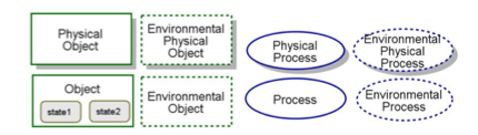
Fig. 1. OPM building blocks: Object, Process, State, essence (shade), affiliation (contour)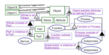
Fig. 2. OPM Structural Relations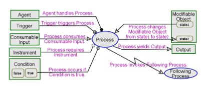
Fig. 3. OPM Procedural Relations OPM copes with complexity via detail-level decomposition, as opposed to aspect decomposition into structure, behavior, state transitions, activities, time flow, etc. that UML and SysML rely on. The hierarchically-organized OPDs are derived from each other using several refinement-abstraction mechanisms: i) unfolding and folding of structural hierarchies of things, ii) zooming into or out of the inner details of things (as shown in Fig. 4, iii) state expressing (showing) and suppressing (hiding) and iv) view creating – expressing additional information on or around pivotal elements through dedicated views. Every model fact needs to be defined at least once in some OPD in order for it to be true for the entire model. A model fact can appear in any one of the OPDs in the OPD set specifying the model. Any model fact can be replicated in any OPD, but it applies to any OPD even if it is not expressed in it explicitly. OPM models can be constructed with the freely available OPCAT V4.01 [31]. OPCAT provides a graphical user interface (GUI) for analysts to create, manage, and share their models. It
supports most OPM concepts, and immediately validates model edits according to OPM syntax and rules. OPCAT also automatically generates OPL sentences in response to graphical model edits, and provides whole-model or diagram-level textual OPL specifications. OPCAT provides a built-in qualitative simulation engine, which supports model validation, verification, and testing, and is especially useful in visualizing the execution of complex interactions. A screenshot of the OPCAT GUI is shown in Fig. 5.
Object In-zooming: object A consists of object B and exhibits process C Process In-zooming: process A consists of process B and exhibits object C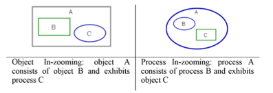
Fig. 4. Object and Process In-Zooming in OPM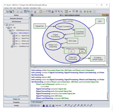
Fig. 5. OPCAT V4.0 Screenshot OPM does not associate shape contour and interior color with model semantics. OPCAT’s default colors for shape contours in the OPDs and thing names in the OPL text are green for objects, blue for processes, and khaki for states. These colors can change and have no formal semantics. Color is used for improved visual model readability. OPCAT also colors outzoomed thing contours in thick grey and folded things’ in thick red. OPCAT allows the modeler to change the contour and interior colors of objects and processes for visual readability or for color-based domain semantics. We can, for instance, use the default interior color grey for “current state” and a different color, say, white, for “future state”.
1 OPCAT free download is available at http://esml.iem.technion.ac.il/?page_id=1849
III. OFUS: OPERATIONAL-FUNCTIONAL UNIFIED SPECIFICATION
In this section we specify OFUS – a modeling pattern that concurrently accommodates the operational or business-related scenario on the one hand and the systemic functionality on the other hand. We begin by making several observations concerning the relations between operational and functional processes. We define the baseline, trivial modeling pattern, in which system functionality is the scenario. We then extend this pattern so it becomes operational-functional, i.e., it describes both the operational scenario and the behavior of the system.
A. The Nominal Model Pattern
We first define a nominal OPM model and the corresponding nominal modeling pattern in Fig. 6. This baseline model pattern is the anchor—a starting point for the functionality-scenario distinction. We define System as comprising several Subsystems. System has some high-level Functionality. Functionality is a set of functions that collectively provide some system capability. Functions may be members of several Functionalities. For instance, administration functions may be regarded as members of the administration functionality, while each administrative function relating to some capability may be regarded as a constituent of that capability.
ID OPL Sentence 100 System exhibits Functionality. 110 Functionality consists of Function. 200 System consists of many Subsystems. 210 Subsystem is physical. 220 Subsystem exhibits Function. 221 Function requires Resource Set. 222 Function affects Affectee Set. 223 Function consumes Input. 224 Function yields Output. 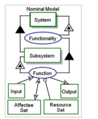
Fig. 6. Nominal System OPM Pattern: OPD (top) and OPL (bottom)
Functionality is abstract and emergent, while its constituent Functions are actual operations of the Subsystems. The nominal model captures the system in its operational form and function, as is or as intended.
B. Functionality-Scenario Distinction
We now extend the modeling pattern to include the Scenario concept next to Functionality. A scenario is a possible sequence of system-related activities. For each system-of-interest (SoI) there exists a higher-level enveloping system (ES)—the SoI and its environment—which fully contains all the processes (activities) and the involved objects that comprise a scenario. Hence, a scenario is always a seed-function of some ES. The same functionality can support several scenarios via subsets of its constituent functions. It is important to distinguish functionalities from scenarios. While these two collections of processes may seem similar and sometimes interchangeable, and may be defined as UML use cases either way, they serve for different purposes in modeling, architecting, and design. Functionalities are conceptual containers of functions that deliver synergistic value to SoI beneficiaries. As such, functionalities are refined via unfolding – the detailing of constituent components and properties. Scenarios deliver value through ordered execution of activities. As such, scenarios are refined via in-zooming – the detailing of the internal temporal {/spatial} ordering of execution {/deployment} of processes {/objects}. Various scenarios may rely on some function in several contexts. A common example is user authentication, which is part of the user management functionality, as well as of several operational scenarios, such as wire transfer or loan request in a bank service system. We make the distinction between a system-contained scenario (SCS) and a system-reliant scenario (SRS). A SCS is a procedure or process that contains only functions of the SoI. This is a process which the SoI or one of its subsystems can perform. Each function of a system is a SCS, but not every SCS is a function. A SRS involves at least one activity that is a function of the SoI (or its outcome) and at least one activity which is not a function of the SoI. Any SRS (a higher-level scenario) is therefore a SCS (a lower-level scenario) of the ES (the system that contains the SoI and is therefore at a higher level than the SoI level). In the nominal case it is implicitly assumed that the scenario in which the system is involved is none other than the system’s function, i.e. that it is a SCS rather than a SRS. The OFUS pattern is shown in Fig. 7. The Enveloping System (ES) consists of System and Environment. The ES exhibits Operation, which consists of one or more SystemReliant Scenarios. These consist of both systemic and external Activities. Systemic Activities invoke the Subsystems’ Functions which compose the Functionalities of the System. As explained, the light cyan color of the environmental things improves diagram readability but has no formal semantics. Unlike Functionality, which relates to the functional system aspect, Scenario relates to the behavioral aspect: It is a set of Functions aimed at accomplishing some goal or objective. A Scenario can encompass several systems and users. The distinction between Functionality and Scenario provides for modeling two system aspects—the functional and the
procedural—within the same model. This way, we can model emergent system traits or behavior, as its functionality—a specific combination of functions, whose value to some beneficiary is greater than the sum of the values of the functions that each individual subsystem provides. The FunctionalityScenario distinction allows for modeling both the functional decomposition of the system and the procedural buildup of added value within the same unified model.
ID OPL Sentence 100 Enveloping System is environmental and physical. 200 Enveloping System exhibits Operation. 210 Operation consists of System-Reliant Scenario. 211 System-Reliant Scenario consists of Activity. 212 System-Reliant Scenario utilizes Functionality. 300 Enveloping System consists of System and Environment. 310 System is physical. 320 System exhibits Functionality. 321 Functionality consists of Function. 330 System consists of many Subsystems. 331 Subsystem is physical. 332 Subsystem exhibits Function. 340 Environment is environmental and physical. 350 Environment exhibits External Activity. 351 External Activity is environmental. 352 External Activity is Activity. 400 Systemic Activity is Activity. 500 Systemic Activity invokes Function.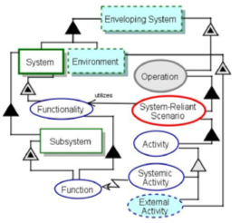
Fig. 7. The Functionality-Scenario OPM pattern Arguably, this approach extends the strictly-functional and strictly-procedural approaches. Preliminary modeling and design can leverage this approach by defining Functionalities and Functions without assigning their execution to specific Subsystems or components, and defining Scenarios based on Functions without necessarily referring to them collectively as Functionalities. This enables an early unified requirements OPM model, based primarily on procedural requirements, which
are mostly operational, user-defined and problem-oriented, followed by functional requirements, which are mostly solutionoriented. The OFUS pattern is therefore useful for early system definition and conceptualization and for high-level and detailed functional specification and design, which are the phases with the most systems engineering impact on the development program. IV. OFUS APPLIED TO SEARCH AND RESCUE MISSION SYSTEMS In this section we describe a generic application of OFUS to a mission system. Mission systems are tasked with performing or supporting organizations, teams, or other systems in performing a mission – a special set of activities intended to obtain a well-defined goal. Mission systems are systems of systems (SoS). A mission SoS consists of at least two processes: mission planning and mission performing. Two respective SoS functionalities (which may be implemented by autonomous or integrated systems) are conceivable, namely: (i) mission planning functionality and (ii) mission functionality. This generic mission OFUS pattern is illustrated in Fig. 8.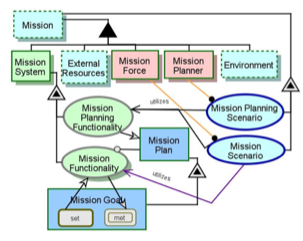
Fig. 8. OFUS pattern of a generic mission with one mission planning scenario and two mission scenarios – planned and unplanned. Consider, for instance, the search and rescue (S&R) mission of missing mountain climbers. The first phase is S&R planning. The second phase is the S&R operation itself, which can include searching, rescuing, or both, depending on the last known location of the climbers group. Once the climbers are located, a decision is made whether to proceed with the rescue operation or allow the climbers to continue the journey. The S&R can be airborne, motorized, on-foot, or some combination thereof, and is often affected by the weather and other conditions in the search area. Each combination of these parameters is a potential scenario or sub-scenario. In some cases, we might be able to combine several options into one scenario. The S&R scenarios rely on varying subsets of S&R system functionalities: (i) S&R Planning (mapping, route planning, deployment planning), (ii) Command & Control (monitoring, communicating, recording, decision making), (iii) Search (imaging, radio-scanning), (iv) Rescue (airborne, on-foot, medical treatment) and (v) Administration (team management,
equipment management). The scenarios may also rely on external functionalities, such as satellite communication, visual search, and weather tracking. The three scenarios, five system functionalities, and their contingency relations are illustrated in Fig. 9. We note several elements in this conceptual model. First, it is the goal of the S&R ES scenarios (not the functionalities) to rescue the climbers. The functionalities are reactive in the sense that they are invoked and activated for the purpose of executing the scenarios that require them. Second, the scenario execution configuration is determined by the climber group’s known location, rather than their physical location, in accordance with the cyber-physical gap modeling pattern [25], [32]. Third, some functionalities are generic and applicable to more than one scenario, while others are specific to a particular scenario.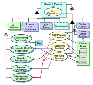
Fig. 9. OFUS-based Search & Rescue (S&R) mission model: S&R planning scenario and two mission scenarios – Searching and Rescuing. In order to demonstrate how several functionalities are utilized in a scenario, in Fig. 10 we zoom into the Searching Scenario. This scenario obviously relies on the Search Functionality, including Imaging and Radio Scanning, as well as on common administration and command & control functions. The Searching Scenario is a repetitive implementation of Search Methods along a set of Search Segments that amount to a Search Route. If the climbers are located during the search, or if the search route has been fully covered, a new S&R Planning cycle is triggered. If the climbers are found, and rescue is needed, a Rescue Scenario is triggered as well. The Searching Scenario relies also on external capabilities, such as Visual Search and Satellite Communication. A subset of the formal OPL textual specification that is automatically generated by OPCAT is attached to the OFUSbased S&R diagram. This subset of OPL sentences focuses on the structure of system functionalities, the outline of searching scenario activities, and most importantly, on function utilization
by scenario activities and conditions for scenario execution, recurrence, and completion. Structural and state-set specifications were omitted. Due to the limited scope of this paper we could not provide a full specification of the S&R system or a complete model. V. DISCUSSION AND CONCLUSION We have presented and discussed the challenge of capturing and analyzing operational scenarios along with systemic functionalities in a unified manner. We have proposed a concept, a framework, and modeling patterns that establish a basis for a solution to this problem. The common approach of aspect decomposition – separating operational and functional aspects to two or more views – is deemed problematic as it creates contradictions, inconsistencies, and concept-design mismatch. Our approach, operational-functional unified specification, OFUS, unifies the two aspects and captures their affinity and mutual utilization. The power of OFUS is in the smooth transition it enables from the problem domain to the solution domain, and the elaboration of operational concepts to architectural-functional design. OFUS utilizes Object Process Methodology, OPM. OPM’s in-zooming mechanism provides for specifying subprocess synchronicity and exploring operational scenarios. OPM’s unfolding mechanism provides for specifying asynchronous processes or process clusters, describing system functionalities, constituent functions, and their allocation to subsystems. OFUS encourages using the concept of enveloping system (ES) – an ensemble of the system-of-interest and its environment. This approach promotes holistic system analysis in a broad context. We have demonstrated OFUS on mission systems such as the Search & Rescue case. This case is a simplified version of a real-world application, which, due to the scope of this paper, could not be fully elaborated. We have also demonstrated the value of this concept in the evolutionary design of ballistic missile defense systems [23], which has inspired the concept extension to the level of a modeling and design framework. Further research is intended to formalize OFUS as a framework, and suggest both a comparative analysis with other approaches, and a constructive approach that relies on OFUS to detect potential operational-functional discrepancies and propose corrective modeling and design steps to mitigate them. We also intend to improve graphic and semantic representations and visual load reduction as well as clarity and expressiveness of OFUS-critical OPM concepts, such as the invocation link and other dedicated syntax and semantics elements.
ACKNOWLEDGMENT This research was supported by Gordon Center for Systems Engineering at the Technion – Israel Institute of Technology, under grants 2021752 and 2014927. We thank the anonymous referees for their useful feedback and advice on paper improvement and future research.
ID OPL Sentence 10000 Search Functionality consists of Imaging and Radio Scanning. 12000 Administrative Functionality consists of Team Managementand Equipment Management. 14000 Rescuing Scenario occurs if Rescue Needed? is yes. 16000 Command & Control Functionality consists of Navigating, Communicating, Decision Making, and Recording. 16100 Decision Making yields Rescue Needed?. 16200 Recording changes Climber Group Location from unknownto known. 17000 Satellite Communicating is environmental. 18000 Visual is environmental. 19000 Searching Scenario exhibits Result and Last Segment?. 21000 Searching Scenario zooms into Search Team Staffing, Search Equipment Preparing, Search Initiating, Route Segment Covering, Location Recording, Reporting, Search Continuation, Replanning, and Search Completion, as well as Last Segment? and Result. 21300 Search Team Staffing requires planned Search Plan. 21400 Search Team Staffing invokes Team Management. 21500 Search Equipment Preparing requires Search Method. 21600 Search Equipment Preparing invokes Equipment Management. 21700 Search Initiating changes Search Plan from plannedto started. 21800 Route Segment Covering requires Search Segment. 21900 Route Segment Covering yields Last Segment? and Result. 22000 Route Segment Covering invokes Visual, Radio Scanning, Navigating, and Imaging. 22100 Location Recording occurs if Result is positive. 22200 Location Recording invokes Decision Making and Recording. 22300 Reporting requires Result. 22400 Reporting invokes Satellite Communicating and Communicating. 22500 Search Continuation occurs if Result is negativeand Last Segment?is no. 22600 Search Continuation consumes Last Segment?. 22700 Search Continuation invokes Route Segment Covering. 22800 Replanning occurs if Result is negative and Last Segment?is yes. 22900 Replanning changes Search Plan from started to planned. 23000 Replanning invokes Search Completion and S&R Planning Scenario. 23100 Search Completion changes Search Plan from startedto complete.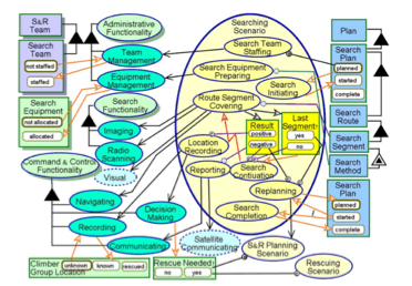
Fig. 10. OFUS-based S&R mission model: search scenario utilizing search, administrative, and command & control functionalities.
REFERENCES
[1] A. P. Sage and S. M. Biemer, “Processes for System Family Architecting, Design, and Integration,” IEEE Syst. J., vol. 1, no. 1, pp. 5–16, 2007.
[2] H. Kaindl, “A design process based on a model combining scenarios with goals and functions,” IEEE Trans. Syst. Man Cybern. Part A Syst. Humans, vol. 30, no. 5, pp. 537–551, 2000.
[3] G. Booch, J. Rumbaugh, and I. Jacobson, The Unified Modeling Language User Guide, vol. 3. 1998.
[4] F. Demoly, D. Monticolo, B. Eynard, L. Rivest, and S. Gomes, “Multiple viewpoint modelling framework enabling integrated product–process design,” Int. J. Interact. Des. Manuf., vol. 4, no. 4, pp. 269–280, Oct. 2010.
[5] R. Heldal, “Use cases are more than System Operations,” in 2nd International Workshop on Use Case Modelling, WUsCaM-2005, 2005.
[6] H. Gomaa and E. Olimpiew, “The role of use cases in requirements and analysis modeling,” in 2nd Int.Workshop on Use Case Modeling (WUsCaM-05): Use Cases in Model-Driven Software Engineering, 2005.
[7] D. Dori, Object-Process Methodology: A Holistic Systems Approach. Berlin, Heidelberg, New York: Springer, 2002.
[8] ISO/TC 184, ISO/PAS 19450:2015 Automation systems and integration — Object-Process Methodology, no. 1. ISO, 2015.
[9] J. M. Carroll, “Scenario-Based Design,” in Hanbook of HumanComputer Interaction, M. G. Helander, T. K. Landauer, and P. V. Prabhu, Eds. Elsevier, 1997, pp. 383–406.
[10] M. B. Rosson and J. M. Carroll, “Scenario-based design,” HumanComputer Interact. Dev. Process, p. 145, 2009.
[11] J. Carroll, “Five reasons for scenario-based design,” Interact. Comput., 2000.
[12] H. Ben-Abdallah and S. Leue, “MESA: Support for Scenario-Based Design of Concurrent Systems,” Lect. notes Comput. Sci., vol. 1384, no. 1384, pp. 118–135, 2008.
[13] F. Bordeleau and B. Selic, “A Scenario-Based Approach to Hierarchical State Machine Design,” in Third IEEE International Symposium on Object-Oriented Real-Time Distributed Computing (ISORC), 2000, pp. 78 – 85.
[14] S. V. Gheorghita, F. Vandeputte, K. De Bosschere, M. Palkovic, J. Hamers, A. Vandecappelle, S. Mamagkakis, T. Basten, L. Eeckhout, H. Corporaal, and F. Catthoor, “System-scenario-based design of dynamic embedded systems,” ACM Trans. Des. Autom. Electron. Syst., vol. 14, no. 1, pp. 1–45, 2009.
[15] D. Harel, H. Kugler, and A. Pnueli, “Synthesis revisited: Generating statechart models from scenario-based requirements,” in Formal Methods in Software and Systems Modeling, vol. Lecture No, no. 287, 2005, pp. 309–324.
[16] DoD, “DoD Architecture Framework Version 2.02,” 2009.
[17] M. Hause, “The Unified Profile for DoDAF/MODAF (UPDM) enabling systems of systems on many levels,” in 2010 IEEE International Systems Conference, 2010, pp. 426–431.
[18] M. Hause, “Rebuilding the Tower of Babel The Case for a Unified Architecture Framework,” in INCOSE Internaional Symposium 2013, 2013.
[19] D. Dori, “Analysis and Representation of Computer Vision Systems By the Object-Process Methodology,” IAPR Work. Mach. Vis. Appl., 1994.
[20] D. Dori, Model-Based Systems Engineering with OPM and SysML. New York: Springer, 2016.
[21] D. Dori, “Object-Process Methodology for Structure-Behavior Codesign,” in Handbook of Conceptual Modeling, D. W. Embley and B. Thalheim, Eds. Berlin, Heidelberg: Springer Berlin Heidelberg, 2011, pp. 209–258.
[22] Y. Mordecai and D. Dori, “Conceptual Modeling of System-Based Decision-Making,” in INCOSE Internaional Symposium, 2014.
[23] Y. Mordecai and D. Dori, “Agile Modeling of an Evolving Ballistic Missile Defense System with Object-Process Methodology,” in 9th IEEE Systems Conference, 2015.
[24] Y. Mordecai and D. Dori, “I5 : A Model-Based Framework for Architecting System-of-Systems Interoperability, Interconnectivity, Interfacing, Integration, and Interaction,” in INCOSE International Symposium, 2013.
[25] Y. Mordecai, O. Orhof, and D. Dori, “Modeling Software Agent Awareness of Physical-Informatical Essence Duality,” in IEEE International Conference of Software Science, Technology, and Engineering - SwSTE 2014, 2014.
[26] Y. Mordecai and D. Dori, “Model-Based Protocol Engineering: Specifying Kerberos with Object-Process Methodology,” in IEEE 28-th Convention of Electrical and Electronics Engineers in Israel, 2014.
[27] J. Somekh, M. Choder, and D. Dori, “Conceptual Model-based Systems Biology: mapping knowledge and discovering gaps in the mRNA transcription cycle.,” PLoS One, vol. 7, no. 12, p. e51430, Dec. 2012.
[28] J. Somekh, G. Haimovich, A. Guterman, D. Dori, and M. Choder, “Conceptual Modeling of mRNA Decay Provokes New Hypotheses,” PLoS One, vol. 9, no. 9, p. e107085, 2014.
[29] A. Sharon, O. L. De-Weck, and D. Dori, “Improving Project-Product Lifecycle Management with Model-Based Design Structure Matrix : A Joint Project Management and Systems Engineering Approach,” Syst. Eng., vol. 16, no. 4, pp. 413–426, 2013.
[30] A. Sharon and D. Dori, “A Project–Product Model–Based Approach to Planning Work Breakdown Structures of Complex System Projects,” Systems, pp. 1–11, 2014.
[31] D. Dori, C. Linchevski, and R. Manor, “OPCAT – An Object-Process CASE Tool for OPM-Based Conceptual Modelling,” in 1st International Conference on Modelling and Management of Engineering Processes, 2010, pp. 1–30.
[32] Y. Mordecai, C. Chapman, and D. Dori, “Conceptual Modeling Semantics for the Physical-Informatical Essence Duality Problem,” in IEEE International Conference on Systems, Man, and Cybernetics - SMC2013, 2013.

若有收获,就点个赞吧
0 人点赞
