SDK 应用开发说明
本文档主要是协助用户快速熟悉杰理 AC79 的 SDK 流程和框架,来完成 AC79_DevKitBoard 的相关软件开发工作。
参考文档: https://doc.zh-jieli.com/AC79/zh-cn/master/getting_started/sdk_app_development/index.html
下面是杰理开发的三条重要信息:
- 杰理开发重点关注:board.c 和 app_config.h
- 杰理开发重点关注:board.c 和 app_config.h
- 杰理开发重点关注:board.c 和 app_config.h
borad.c里面定义了开发板相关的外设io口配置, app_config.h中声明了相关的功能开关
- 在board.c文件中, 将串口波特率改为115200
- 在app_config.h文件中定义CONFIG_DEBUG_ENABLE,打开串口调试
#if CONFIG_DEBUG_ENABLEUART1_PLATFORM_DATA_BEGIN(uart1_data)//打印串口.baudrate = 115200,//.port = PORT_REMAP,//任意IO通道#if CONFIG_AUDIO_ENC_SAMPLE_SOURCE == AUDIO_ENC_SAMPLE_SOURCE_PLNK0.output_channel = OUTPUT_CHANNEL3,//选择映射输出通道#else.output_channel = OUTPUT_CHANNEL0,#endif.tx_pin = IO_PORTB_03,.rx_pin = -1,.max_continue_recv_cnt = 1024,.idle_sys_clk_cnt = 500000,.clk_src = PLL_48M,.flags = UART_DEBUG,UART1_PLATFORM_DATA_END();#endif
按键
按键的配置
这个案例中,我们以adc按键为例,我们首先打开DevKitBoard.c文件,找到与按键相关的配置
当我们看到这种带有#if 条件 的宏定义的时候, 首先想想这个宏定义有没有配置,在哪里配置,当然是在前面讲过的app_config.h文件里面配置了啊,重要的事情已经说过三遍啦!#if TCFG_ADKEY_ENABLE#define ADKEY_UPLOAD_R 22#define ADC_VDDIO (0x3FF)#define ADC_09 (0x3FF)#define ADC_08 (0x3FF)#define ADC_07 (0x3FF * 150 / (150 + ADKEY_UPLOAD_R))#define ADC_06 (0x3FF * 62 / (62 + ADKEY_UPLOAD_R))#define ADC_05 (0x3FF * 36 / (36 + ADKEY_UPLOAD_R))#define ADC_04 (0x3FF * 22 / (22 + ADKEY_UPLOAD_R))#define ADC_03 (0x3FF * 13 / (13 + ADKEY_UPLOAD_R))//#define ADC_02 (0x3FF * 75 / (75 + ADKEY_UPLOAD_R * 10))//#define ADC_01 (0x3FF * 3 / (3 + ADKEY_UPLOAD_R))#define ADC_00 (0)#define ADKEY_V_9 ((ADC_09 + ADC_VDDIO)/2)#define ADKEY_V_8 ((ADC_08 + ADC_09)/2)#define ADKEY_V_7 ((ADC_07 + ADC_08)/2 + 50)#define ADKEY_V_6 ((ADC_06 + ADC_07)/2)#define ADKEY_V_5 ((ADC_05 + ADC_06)/2)#define ADKEY_V_4 ((ADC_04 + ADC_05)/2)#define ADKEY_V_3 ((ADC_03 + ADC_04)/2)//#define ADKEY_V_2 ((ADC_02 + ADC_03)/2)//#define ADKEY_V_1 ((ADC_01 + ADC_02)/2)//#define ADKEY_V_0 ((ADC_00 + ADC_01)/2)const struct adkey_platform_data adkey_data = {.enable = 1,.adkey_pin = IO_PORTB_01,.extern_up_en = 1,.ad_channel = 3,.ad_value = {//ADKEY_V_0,//122 //0~122//ADKEY_V_1,//192 //122~192//ADKEY_V_2,//319 //192~319ADKEY_V_3,//445 //319~445ADKEY_V_4,//572 //445~572ADKEY_V_5,//694 //572~694ADKEY_V_6,//823 //694~823ADKEY_V_7,//1007 //823~1007ADKEY_V_8,//1023 //1007~1023ADKEY_V_9,//1023 //1023},.key_value = {KEY_5,KEY_4,KEY_3,KEY_2,KEY_1,NO_KEY,NO_KEY,},};#endif
打开app_config.h文件,先搜索TCFG_ADKEY_ENABLE有没有配置,若没有配置,则配置
#define TCFG_ADKEY_ENABLE 1 //AD按键
按键的回调
我们可以在app_main.c文件中的事件回调函数中,增加按键相关的回调函数,下面的打印的value就是我们在board.c文件里面配置的value值
static int app_demo_event_handler(struct application *app, struct sys_event *sys_event){switch (sys_event->type) {case SYS_NET_EVENT:break;case SYS_KEY_EVENT:struct key_event* key = (struct key_event *)sys_event->payload;printf("key=%d value=%d \n",key->action,key->value);break;default:return false;}}
参考文档:https://doc.zh-jieli.com/AC79/zh-cn/master/module_example/peripherals/key.html
GPIO
gpio开发相对来说要简单很多,我们以点亮开发板上面的led灯为例,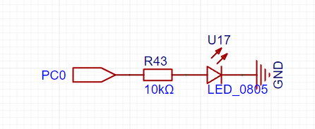
代码实现
#include "app_config.h"#include "system/includes.h"#include "asm/pwm.h"#include "device/device.h"#define ITHEIMA_LED_PIN IO_PORTC_00void itheima_led_init(){}void itheima_led_set_status(uint8_t state){gpio_direction_output(ITHEIMA_LED_PIN, state);}void itheima_test_led_task(){int i = 0;while(1){itheima_led_set_status(i);i = !i;os_time_dly(100);}}void itheima_test_led_main(){os_task_create(itheima_test_led_task,NULL,10,512,0,"itheima_test_led_task");}late_initcall(itheima_test_led_main);
参考文档:https://doc.zh-jieli.com/AC79/zh-cn/master/module_example/peripherals/gpio.html
PWM

配置
在board.c文件中配置
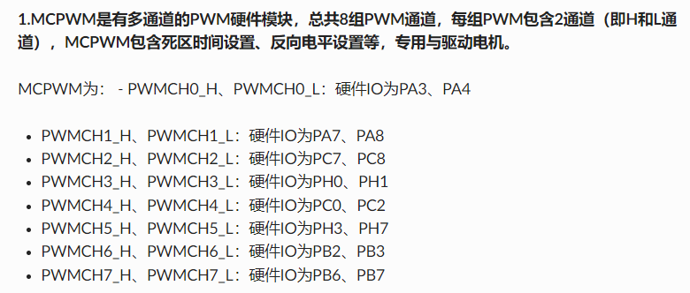
PWM_PLATFORM_DATA_BEGIN(pwm_data2).port = IO_PORTC_02,//选择定时器的TIMER PWM任意IO,pwm_ch加上PWM_TIMER3_OPCH3或PWM_TIMER2_OPCH2有效,只支持2个PWM,占用output_channel2/3,其他外设使用output_channel需留意.pwm_ch = PWMCH4_H,//初始化可选多通道,如:PWMCH0_H | PWMCH0_L | PWMCH1_H ... | PWMCH7_H | PWMCH7_L | PWM_TIMER2_OPCH2 | PWM_TIMER3_OPCH3 ,.freq = 1000,//频率.duty = 50,//占空比.point_bit = 0,//根据point_bit值调节占空比小数点精度位: 0<freq<=4K,point_bit=2;4K<freq<=40K,point_bit=1; freq>40K,point_bit=0;PWM_PLATFORM_DATA_END()
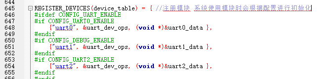
配置完成之后,还要记得注册设备
REGISTER_DEVICES(device_table) = { //注册模块 系统使用模块时会根据配置进行初始化#ifdef CONFIG_PWM_ENABLE{ "pwm1", &pwm_dev_ops, (void *)&pwm_data1},{ "pwm2", &pwm_dev_ops, (void *)&pwm_data2},/* { "pwm_led",&pwm_led_ops, (void *)&pwm_led_data}, */#endif
示例代码:
void itheima_led_test_pwm_task(){// 1. 打开pwm设备void *pwm_dev_handl = NULL;struct pwm_platform_data pwm = {0};/*1.open */pwm_dev_handl = dev_open("pwm2", &pwm);//打开PWM0设备,传参可以获取board.c配置的参数if (!pwm_dev_handl) {printf("open pwm err !!!\n\n");return ;}printf("pwm : ch=0x%x,duty=%2f%%,pbit=%d,freq=%dHz\n", pwm.pwm_ch, pwm.duty, pwm.point_bit, pwm.freq);// 2. 运行pwmdev_ioctl(pwm_dev_handl, PWM_RUN, (u32)&pwm);int i = 100;while (1) {// 3. 改变pwm占空比pwm.duty = i;dev_ioctl(pwm_dev_handl, PWM_SET_DUTY, (u32)&pwm);//设置占空比os_time_dly(5);i--;// 条件判断if(i < 0){i = 100;}}}void itheima_test_led_main(){os_task_create(itheima_led_test_pwm_task,NULL,10,512,0,"itheima_led_test_pwm_task");}late_initcall(itheima_test_led_main);
参考文档: https://doc.zh-jieli.com/AC79/zh-cn/master/module_example/peripherals/pwm.html
串口收发
首先需要对串口进行相应的配置,让它能够支持收发数据, 在board.c文件中进行如下配置
#if CONFIG_DEBUG_ENABLEUART1_PLATFORM_DATA_BEGIN(uart1_data)//打印串口.baudrate = 115200,//.port = PORT_REMAP,//任意IO通道#if CONFIG_AUDIO_ENC_SAMPLE_SOURCE == AUDIO_ENC_SAMPLE_SOURCE_PLNK0.output_channel = OUTPUT_CHANNEL3,//选择映射输出通道#else.output_channel = OUTPUT_CHANNEL0,#endif.input_channel = INPUT_CHANNEL3,.tx_pin = IO_PORTB_03,.rx_pin = IO_PORTB_04,.max_continue_recv_cnt = 1024,.idle_sys_clk_cnt = 500000,.clk_src = PLL_48M,.flags = UART_DEBUG,UART1_PLATFORM_DATA_END();#endif
串口初始化
void icheima_uart_init(char* name){hdl = dev_open(name, NULL);if (!hdl) {printf("open uart err:%s !!!\n",name);return ;}/* 1 . 设置接收数据地址 */dev_ioctl(hdl, UART_SET_CIRCULAR_BUFF_ADDR, (int)uart_buf);/* 2 . 设置接收数据地址长度 */dev_ioctl(hdl, UART_SET_CIRCULAR_BUFF_LENTH, sizeof(uart_buf));/* 3 . 设置接收数据为阻塞方式,需要非阻塞可以去掉,建议加上超时设置 */dev_ioctl(hdl, UART_SET_RECV_BLOCK, 1);//u32 parm = 500;//接收函数的超时时间要比发送函数超时时间小//dev_ioctl(hdl, UART_SET_RECV_TIMEOUT, (u32)parm);/* 4 . 使能特殊串口 */dev_ioctl(hdl, UART_START, 0);printf("---> icheima_uart_init uart_recv_test_task running \n");}
收数据
/**接收数据*/int icheima_uart_read_data(uint8_t* buf){int len = dev_read(hdl, buf, 64);if (len <= 0) {printf("\n uart recv err len = %d\n", len);if (len == UART_CIRCULAR_BUFFER_WRITE_OVERLAY) {printf("\n UART_CIRCULAR_BUFFER_WRITE_OVERLAY err\n");dev_ioctl(hdl, UART_FLUSH, 0); //如果由于用户长期不取走接收的数据导致循环buf接收回卷覆盖,因此直接冲掉循环buf所有数据重新接收} else if (len == UART_RECV_TIMEOUT) {puts("UART_RECV_TIMEOUT...\r\n");}}return len;}#ifdef USE_ICHEIMA_UART_DEMO_TEST#include "json.h"// 串口接收到消息之后,就将消息发给gd32static void uart_recv_test_task(void *priv){int len=0;uint8_t recv_buf[1024];printf("uart_recv_test_task start>>>>>>>>>>>>>>>>>\r\n");json_object *new_obj;const char *json_str, *str_ssid, *uuid;while(1){len=icheima_uart_read_data(recv_buf);printf("\n uart recv len = %d\n", len);if(len > 0){printf("\n uart recv len = %d\n", len);//recv_buf[len] = '\0';memset(recv_buf, 0, sizeof(recv_buf));}else{printf("uart recv error len = %d\n", len);}}}
启动收消息的线程
os_task_create(uart_recv_test_task, NULL, 10, 1000, 0, "uart_recv_test_task");
发数据
/**向外面发送数据*/void icheima_uart_send_data(uint8_t* data, uint32_t len){dev_write(hdl, data, len);}
一些配置说明
修改蓝牙名称
apps/common/config/user_cfg.c文件中找到下面这个函数,将它修改为自己想要的名称
注意: 以”JL-“开头, 方便继续后续的学习
const char *bt_get_local_name(void){#ifndef CONFIG_RF_TEST_ENABLEconst u8 *mac_addr;mac_addr = bt_get_mac_addr();sprintf(edr_name, "JL-ICHEIMA-%02X%02X", mac_addr[4], mac_addr[5]);#endifreturn edr_name;}
参考文档: https://doc.zh-jieli.com/Tools/zh-cn/dev_tools/dev_env/index.html

若有收获,就点个赞吧
0 人点赞
